 ASVAB Camp
Why hidden edges matter
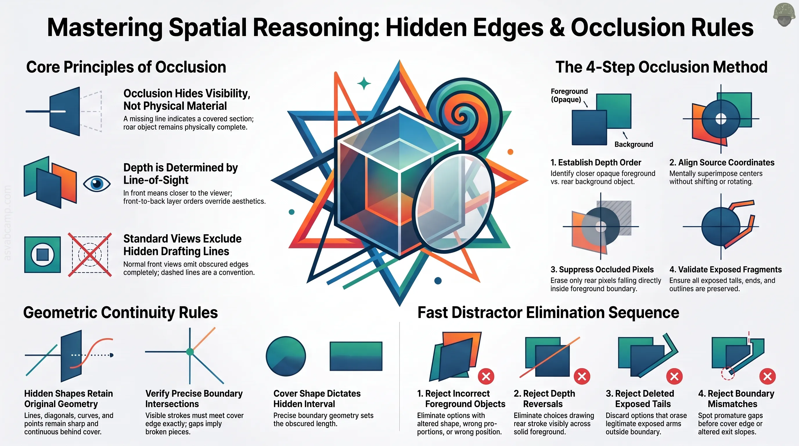
When one object is in front of another, some of the rear object may disappear from the visible picture even though the rear object has not changed. This phenomenon is occlusion. Spatial assembly problems ask you to preserve the identity and position of each part while deciding which boundaries a viewer can actually see. Do not assume a missing line means a missing piece. The missing part may be covered by a closer opaque surface.
Where this lesson fits on the ASVAB
The Assembling Objects (AO) subtest measures the ability to judge how separate objects will look when their parts are placed together. Hidden edges are a useful component of that broader skill, not a promise that any particular hidden-edge question will appear. Our pictures and answer choices are independently authored practice examples. They are not copied from secure ASVAB items, and no memorized drawing is needed to apply the reasoning.
What the observer sees
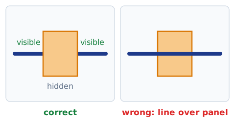
Imagine looking straight at two flat cutouts. A dark blue rod sits behind a solid light orange panel. The observer sees all exposed rod segments but cannot see the rod where the panel blocks the line of sight. When asked for a normal front view, draw the panel on top of the rod. A line through the solid face is incorrect unless the instructions specifically request an X-ray or hidden-line drawing.
Opaque versus transparent
An opaque face prevents light from the object behind it from reaching the viewer. A transparent face can reveal the background, sometimes with a tint; a wireframe is only a representation of edges. These conventions are not interchangeable. If a question labels a cover as opaque, treat the covered part as invisible in the final picture even if the original separated-components diagram shows its complete shape.
Front and back are relationships
The word front does not mean the top of the page. It means closer to the observer along the viewing direction. A panel can be lower on the page and still be in front of another object. Locate the viewing arrow or the instruction that names the forward layer. Use that depth order, not an intuitive preference for a shape appearing higher in the illustration.
The line-of-sight test
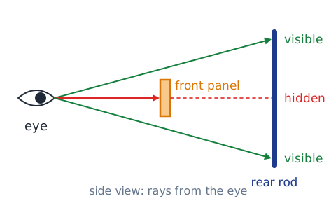
For any point on an object, imagine a straight ray traveling from the eye to that point. If the ray hits a closer opaque surface first, the point is hidden. If nothing closer blocks it, the point is visible. This simple test works for solid shapes, rods, cutouts, and complicated overlapping silhouettes. It also explains why one rear edge may remain visible while another edge becomes completely concealed.
Visible contours versus covered contours
A visible contour is an exposed boundary that separates the object from the background or another visible surface. A covered contour continues behind an occluder but should not be drawn as a solid line through the occluder. The hidden boundary is still part of the object. To solve the picture, track physical continuity separately from the marks that should appear on the finished front-facing drawing.
Partial coverage
A rear line may be visible to the left of an opaque panel, hidden across the middle, and visible again on the right. Those two visible pieces need not be two different objects. Check whether their direction, thickness, markings, and end locations can belong to one original part. A mistake is to join the visible ends with a visible line over the covering panel.
Total coverage
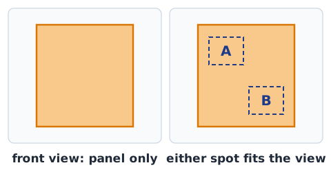
Sometimes the closer object hides an entire small component. The absence of a visible rear shape is not proof it was omitted. Check the instructions: if all supplied parts must be present, the assembly can still contain a wholly concealed part. In these cases, the displayed view might not prove the hidden component’s exact placement without additional conditions. Do not invent certainty when more than one placement fits.
A boundary at the cover
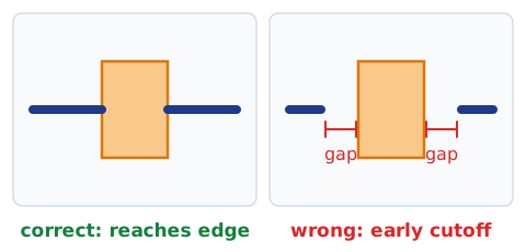
When a long thin object enters behind a panel, its exposed stroke normally ends exactly at the panel boundary. A small premature gap incorrectly suggests that part of the rod disappeared before it reached the panel. A stroke continuing into the panel also violates opaque coverage. Inspect the precise intersection of rod and cover rather than deciding solely from the center of the diagram.
Layer order is the deciding rule
For a simple 2-D drawing, the visual result depends on paint order. Draw the rear object first and the foreground opaque surface second. The foreground covers the overlapping rear pixels. Reversing that order creates an incorrect picture in which the rear object appears in front. The same rule generalizes to three layers, provided their front-to-back ordering has been specified consistently.
The rear object remains continuous
Occlusion removes visibility, not material. If a given source drawing shows a straight line, it remains straight behind the cover unless a bend is explicitly permitted. If it shows an arc, the hidden portion remains part of that same arc. Never transform the source merely to make a tempting answer option look plausible. Use geometry and physical identity to reject impossible reconstructions.
Recognizing a straight segment
A straight rear segment passing beneath a solid panel may emerge on the same geometric line. Extend each visible portion mentally with a ruler, and see whether the extensions agree with the source. This continuation is an inference, not a license to draw it over the opaque front surface. In our visual questions the source box provides the complete rod, so the correct hidden path is not ambiguous.
Recognizing a diagonal
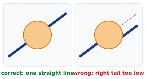
A diagonal rod rises or falls as it crosses the page. If it enters a cover at one height, it may exit at a different height. That difference can be perfectly consistent with one straight diagonal. Compare the direction of the two exposed tails to the original source image. A distractor may hide the right tail at the wrong vertical position or reverse the slope.
Curves behind an occluder
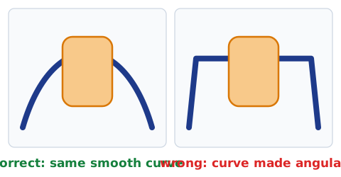
A rounded curve can enter a cover on one side and emerge on the other side at a similar or different height. A smooth original curve does not become angular because it is partly hidden. In the separated source image, inspect its curvature before you combine the layers. In the final view, only those portions not covered by the foreground object should be drawn as solid contours.
Crossing rods and junctions
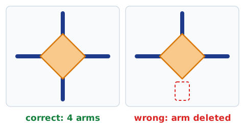
Two rear rods can cross beneath a single foreground plate. Four ends may appear around the plate while the crossing itself is concealed. The number of visible tails is not necessarily the number of independent original rods. If the source specifies a cross, both rear strokes survive; they are simply masked within the closer plate. Do not delete one entire arm to simplify the picture.
Broken-line distractors
A line that stops well before the foreground object and starts again well after it can look superficially similar to true occlusion. However, if the original rear segment reaches the panel boundary, the exposed line should reach that boundary too. The incorrect early cutoff creates extra blank space. Examine both entry and exit points rather than simply counting visible ends.
Hidden-line drafting convention
Technical drawings sometimes use short dashed strokes to indicate edges hidden behind visible surfaces. That is a deliberate communication convention, not a literal view of an opaque object. Our main multiple-choice pictures request an ordinary visible-surface front view. Therefore, a dashed line printed across the solid cover is not the requested appearance. In a separate engineering-drawing exercise with explicit hidden-line instructions, the rule can be different.
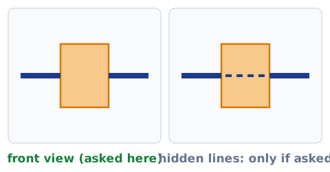
Silhouette does not show every detail
An outer silhouette is the union of what is visible at the boundary of the assembled scene. It does not necessarily reveal every internal connection. A candidate with the right outside shape can still be wrong if the internal foreground cover is drawn behind a rear element. Always check both the outline and the occluding seams in the middle, especially where lines touch a visible face.
Occlusion and overlap are not identical
Overlap means two projections occupy some of the same image region; occlusion identifies which projected surface is closer and blocks the other. A transparent overlay can overlap without fully hiding anything. Conversely, an opaque narrow strip can occlude a section of a much longer line. A reliable solution must apply the given depth order and transparency information after identifying the overlapping region.
Reading a viewing arrow
When a diagram includes an eye or an arrow, use it to determine what lies closer along the indicated direction. A view from the opposite side can reverse which element hides the other. A front-to-back relationship alone does not specify what an object looks like from every viewpoint. If the view changes, first re-establish the relative depth of surfaces before tracing any visible edges.
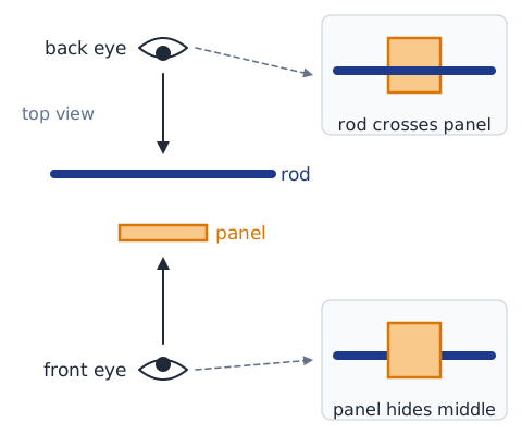
Two-dimensional layering model
Many introductory spatial practice questions can be understood by stacking flat cutouts without perspective. Imagine placing a rear sheet on a table, then an opaque front sheet over it, all aligned to a common grid. Points in the uncovered rear region remain visible. Points in the intersection disappear beneath the front sheet. This model is intentionally simpler than complex 3-D self-occlusion and is useful for building reliable habits.
Three-dimensional caution
In a true 3-D assembly, depth can vary from one point of a surface to another. A curved surface can hide different edges as the observer moves. The flat stack model works only when the given problem justifies it. Before using any simple rule, identify whether the question represents layered 2-D parts or a rotated solid. Avoid applying a 2-D overlap template mechanically to every spatial object.
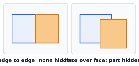
Contact versus hidden overlap
Two pieces can touch along a common edge without one covering the other. In that case, the visible boundary may be shared, but it is not hidden by an overlapping face. Occlusion requires a closer area to project over another area. Distinguish edge-to-edge assembly from face-over-face stacking; the same two pieces can yield different front views depending on how they are connected.
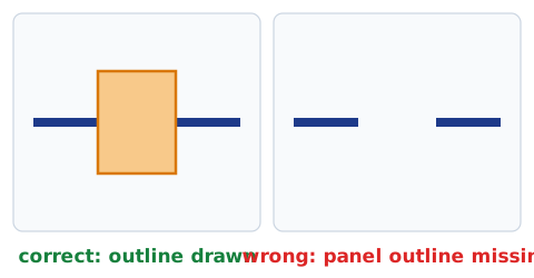
When a seam remains visible
A foreground panel usually has its own outline, and that outline may remain visible where it lies over a rear object. A rear line must stop at the panel boundary, but the panel edge remains part of the final view. A wrong answer may omit the panel outline, making the scene appear as though the line itself had been cut. Follow each object’s visible contours independently.
Thickness and color cues
In our diagrams, a dark blue stroke represents the rear object and a pale orange filled shape represents the opaque foreground cover. Those colors are only instructional cues. The actual geometric rule does not depend on the hues. If a later problem uses black outlines or swapped colors, identify the stated front layer and apply the same covering logic. Shape, alignment, and order are more reliable than decoration.
What a missing tip can mean
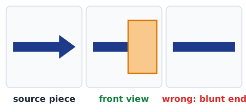
A pointed end may disappear beneath a larger face while the rest of the piece remains visible. The hidden tip does not become blunt. If the provided source includes a distinctive arrowhead, do not replace it with a flat end in your mental reconstruction. The visible final view may omit the tip entirely, but the underlying component must retain its supplied geometry.
The center-alignment convention
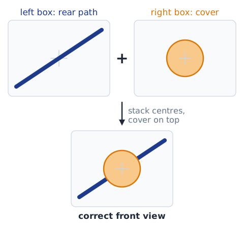
For the visual drills here, the rear object and the foreground cover are drawn on matching local coordinate frames in two separate source boxes. Combine them without stretching, rotating, or shifting either component. The diagrams state that the cover is closer to the viewer. This explicit alignment removes arbitrary placement guesses and makes the question about occlusion itself. If a later problem permits movement, use its separate placement instructions.
How to read the input boxes
The left box shows a complete dark rear path with no cover. The right box shows the solid cover by itself. Both boxes use the same light crosshair at the same local position. Imagine superimposing those coordinate centers, with the pale cover laid on top. The answer images show four possible front views. Select the only one that retains all visible rear portions and hides only the portion actually blocked.
How to read the answer pictures
Each answer is a full composite, not a second set of movable parts. Compare the cover outline and its placement, then inspect the dark path immediately outside the cover on both sides. A wrong option may draw a line across the face, use drafting dashes not requested, erase a legitimate exposed tail, or move the covering plate. Only one alternative should reproduce the specified stack accurately.
The four-stage occlusion method
First name which object is behind and which is in front. Second align their source coordinate centers without changing their dimensions. Third mentally remove only those rear pixels covered by the nearer opaque face. Fourth compare each candidate against the expected exposed fragments and foreground outline. This sequence prevents the common shortcut of choosing whichever option looks visually balanced.
Check front shape before the rear line
Start by comparing the foreground object itself. Its outline should match the source: a circle should not become a diamond, and a rounded rectangle should not become square. The face should remain in the specified location. If a candidate changes the cover, reject it even if its rear path looks convincing. Then compare how the unaltered cover masks the original rear path.
Check the exposed tails
After confirming the covering face, verify that every part of the original rear object outside the cover appears in the final diagram. This is particularly important for a cross or a curved path with several visible fragments. An option can show the hidden middle correctly but accidentally omit the exposed bottom arm. Such a view does not represent the supplied source parts.
Check the covered segment
The ordinary front view must not reveal the rear stroke inside the filled foreground shape. A solid rear line across the plate makes the rear object appear nearer than the plate. A dashed line can be appropriate in certain technical conventions, but not here. The answer must follow the representation requested in the prompt rather than treating every way of illustrating the hidden shape as equally valid.
Distinguishing a gap from a covering
A true occlusion boundary terminates a rear contour exactly where the foreground face begins in projection. A genuine empty gap would continue to show background between the rear contour and the face. These can look alike at low resolution, so zoom or use the vector image when reviewing your answers. Examine whether the dark stroke reaches the edge, not merely whether its middle is absent.
The danger of inferred depth
Never assume a darker shape is automatically in front because it looks bolder. Artists can use color, shading, or shadows for many reasons. The source statement here explicitly identifies the light filled panel as the front layer. That statement overrides a visual guess based on hue or line weight. In another question, reverse the role if the instruction says the dark element is closer.
Visualizing a long narrow cover
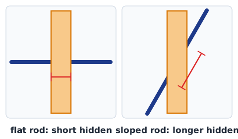
If the foreground object is a vertical strip, it may hide a short central interval of a horizontal rod but a longer segment of a sloped or curved line. The hidden length depends on the intersection geometry, not simply on the strip’s width. Instead of estimating missing lengths, extend the source path through the strip mentally and keep only the portions outside the filled cover in the final view.
Visualizing a circular cover
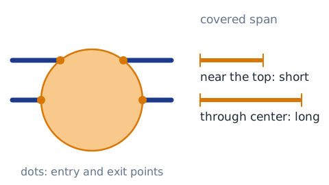
A circular or elliptical face has a changing width at different heights. A line passing through its center is covered for a relatively long span; a line passing near its top or bottom is covered for a shorter span. This follows from the shape of the foreground boundary. The entry and exit points of the visible rear path lie where its projection crosses that boundary.
Visualizing a polygon cover
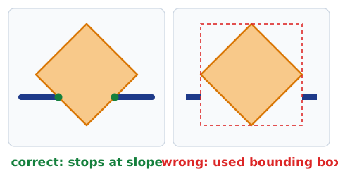
With a diamond or hexagonal cover, the blocking boundary may be diagonal even when the hidden rear segment is horizontal. The visible rear path stops where it meets the sloped edge. Do not substitute the cover’s bounding rectangle; the actual polygon is what blocks the view. A near-miss answer may hide too much or too little of the rear path by treating an angled cover as a full rectangle.
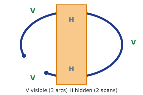
An elliptical rear path
A curved rear object can have several intersections with a foreground plate. Trace the original curve from one endpoint to the other, noting each interval inside the plate. Each interval that lies beneath the opaque surface disappears in the visible composite. An answer showing only one tail might be wrong if a separate exposed arc remains outside the cover.
Multiple rear elements
When the source contains a cross or several connected strokes, each segment must be tested against the foreground face. A panel may conceal the central junction yet leave top, bottom, left, and right arms visible. If an answer loses one entire arm, the source inventory has not been preserved. Do not simplify the object into one straight line just because part of its structure is hidden.
Drawing a visibility map
A quick scratch diagram can mark each region as visible V or covered H. First outline the front face, then mark portions of the rear object outside as V and portions inside as H. You do not need to calculate an exact length to make a correct choice. The marks make it harder to confuse real disappearance of an object with temporary loss of visual access.
A short worked example
A rear straight line travels from the left edge toward the right edge. An opaque rectangular plate covers the middle third. The correct assembled view shows a left line segment, the plate, and a right line segment in the original alignment. The line does not cross the plate as a visible stroke. This example illustrates both continuity of the physical rear object and the hiding action of the nearer face.
Worked example with a diagonal
Suppose a rear diagonal rises from lower left to upper right, and a circular cover occupies the center. The line enters the circle boundary at a lower location on the left and leaves at a higher location on the right. Both exposed tails must continue the original slope. An option with a horizontal right tail would change the source geometry rather than merely hide its central portion.
Worked example with an intersection
Imagine a complete rear cross made from a horizontal and a vertical stroke. A small opaque diamond covers the center. Four exposed arms should be visible outside the diamond while the central crossing is hidden. A candidate with just the left and right arms cannot be correct because the original rear cross also included the vertical stroke, much of which should remain exposed.
Distractor: impossible foreground reversal
One common wrong choice displays the complete dark rear path across the orange foreground face. It may be visually neat because the original path stays intact, but the layering is backwards. The problem specified that the foreground face is opaque and closer to the eye. Preserve the rear geometry physically while suppressing its covered pixels in the visible picture.
Distractor: drafting marks used as a photograph
A dashed line through a cover can communicate a concealed boundary in an engineering sketch. If the problem explicitly asks for that notation, a dashed representation may be correct. However, the present visual items ask for a normal visible-surface appearance. The dashed candidate is a representation mismatch: it reveals a hidden rear element symbolically instead of showing only what is physically visible.
Distractor: deleting exposed geometry
Another answer may hide a rod through the panel correctly but also remove one visible end beyond the panel. This is different from true occlusion. The closer plate cannot block a part of the rod that lies clearly outside the plate’s projected area. Compare the final drawing against the entire original rear path, especially exposed tips and cross arms at the edges of the frame.
Distractor: moving the cover
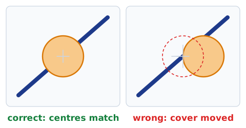
A shifted foreground cover changes which rear pixels become hidden. Unless movement is permitted, a translation of the cover is not part of assembly. The source diagrams in this lesson share the same coordinate center, so the cover must occupy the specified place. A shifted option may show a plausible cover-and-rod overlap, but it is a different configuration and therefore incorrect.
A practical time-saving check
Eliminate candidates in this order: wrong front shape or position, rear line drawn on top, missing exposed tail, then subtle entry and exit discrepancies. The first three checks often identify the error without tracing every curved segment. If two answers still appear plausible, compare the exact boundary intersections against the separated rear and foreground source shapes rather than guessing from overall visual balance.
When not to over-interpret
A single front view sometimes cannot reveal the geometry of a completely covered part. If the question provides no separate rear-object source or alignment rules, several hidden configurations may match the same visible image. Good spatial reasoning includes noticing insufficient information. Our exercises avoid that ambiguity by showing the full original rear path and an aligned cover before asking for the final view.
Guided practice: a horizontal line
Take a rear line drawn through the center of a solid rectangular cover. Place the cover on top, leaving the original line unshifted. The visible answer retains equal-height left and right tails, with no dark stroke through the filled rectangle. A picture with the line crossing the cover has incorrect depth; one with a missing right tail erases an exposed segment.
Guided practice: sloped line and diamond
Take a rear sloping stroke and a diamond-shaped opaque cover aligned to the same center. Visualize where the stroke meets each sloping side of the diamond. These are the endpoints of the visible tails. The hidden interval depends on the exact diamond geometry, not its imagined bounding box. Reject any choice that either changes the stroke’s direction or draws through the diamond face.
Guided practice: cross and circle
Overlay a central circular cover on a complete dark cross. Inspect the four arms separately. Each dark arm remains visible until it meets the circle and reappears outside when applicable. A candidate that paints the cross over the circle reverses depth; a candidate that deletes the lower arm loses exposed geometry. The correct result displays the unaltered circle over the center of the cross.
A source-checking habit
Before accepting a spatial explanation, distinguish official exam scope from a lesson author’s teaching technique. The official AO description identifies the ability to assemble parts mentally; it does not prescribe our labels, color system, or specific distractor types. Those are new educational devices designed to develop the skill. Avoid describing any exercise here as an actual unreleased military test question.
Final recall checklist
Ask four questions. Which surface is closer? Where does the rear object intersect the closer surface in projection? Which rear portions remain outside that surface? Does the candidate preserve both objects while hiding only the covered rear portions? Answering these in order produces a sound comparison even when a line is slanted, curved, or composed of several connected arms.
Bridge to the next topic
Occlusion reasoning combines naturally with rotation, connection-point matching, and part-to-whole assembly. When a future scene allows rotation, transform the part first, align the connectors, then apply the chosen depth order. When no rotation is allowed, preserve the original position before masking. This sequence prevents a correct occlusion rule from being applied to an incorrectly positioned source object.
 English ▾