Can you tell which parts of a rear line stay visible when an opaque shape covers it? This lesson test measures that with 40 original questions. You will judge front views of layered figures, decide where exposed tails should appear, and reject candidates that reverse the foreground, erase visible geometry or move the cover.
An opaque plate is placed in front of a continuous thin rod. What happens to the rod where the plate overlaps it in a direct front view?
Show the answer
Answer: A
An opaque surface blocks light coming from anything behind it, so in a front view the covered stretch of the rod simply is not drawn. That missing stretch is a fact about what the viewer can see, not about the object: the rod continues behind the plate unchanged. The usual misconception is reading a visual gap as a physical break. If you could look from the side or remove the plate, the rod would appear whole.
A (correct): Correct. The opaque front plate blocks visibility of the rod, not its existence. The direct view omits the covered stroke.
B: Incorrect. This answer does not satisfy the specified depth, geometry, or visibility constraints. The opaque front plate blocks visibility of the rod, not its existence. The direct view omits the covered stroke.
C: Incorrect. The plate only blocks the line of sight; nothing cuts the rod, which stays one continuous piece.
D: Incorrect. Drawing the hidden part as a solid line over the plate would show the rod in front of a plate that actually blocks it.
Question 2 of 40 · easy
Two pieces overlap in the picture. Which additional fact determines which one hides the other?
Show the answer
Answer: C
Occlusion depends on depth: along any line of sight, the opaque surface closest to the viewer is the one you see, and it hides whatever lies directly behind it in the overlap. So the deciding fact is which piece is nearer. Properties such as color, width or the order in which pieces are named say nothing about distance from the eye. A dark piece can sit behind a pale one, just as a black car can be hidden behind a white truck.
A: Incorrect. This answer does not satisfy the specified depth, geometry, or visibility constraints. The closest opaque surface controls which more distant pixels are occluded; color and naming are not depth evidence.
B: Incorrect. This answer does not satisfy the specified depth, geometry, or visibility constraints. The closest opaque surface controls which more distant pixels are occluded; color and naming are not depth evidence.
C (correct): Correct. The closest opaque surface controls which more distant pixels are occluded; color and naming are not depth evidence.
D: Incorrect. This answer does not satisfy the specified depth, geometry, or visibility constraints. The closest opaque surface controls which more distant pixels are occluded; color and naming are not depth evidence.
Question 3 of 40 · easy
A source drawing shows a straight rear line entering behind a round opaque cover. Which statement is justified?
Show the answer
Answer: D
Hiding part of an object changes only what is drawn, never the object's shape. A straight line that passes behind a cover still runs straight, so where it reappears on the far side it lines up with the part that entered. You can check a candidate by laying a ruler along the visible segments; they should be collinear. The tempting mistakes are assuming the line bends to follow the cover's curve or ends at its edge, which would change the source shape.
A: Incorrect. This answer does not satisfy the specified depth, geometry, or visibility constraints. Occlusion hides segments, but does not change the straightness of the original object.
B: Incorrect. The line only passes out of sight at the cover edge; being hidden gives no evidence that the object stops there.
C: Incorrect. A hidden line keeps the shape it had; being covered by a round shape does not make a straight line bend.
D (correct): Correct. Occlusion hides segments, but does not change the straightness of the original object.
Question 4 of 40 · easy
A final ordinary front view shows a dark rear stroke drawn solid across a foreground opaque panel. What is wrong?
Show the answer
Answer: C
In an ordinary front view, the nearer opaque surface is drawn last, so it covers anything behind it. If a rear stroke appears solid across the front panel, the drawing has swapped the depth order and shows the rear item as if it were closer. To diagnose this, ask which object the stem places in front and confirm that nothing behind it shows through its face. Treating the panel as transparent or calling the alignment impossible misreads a simple layering mistake.
A: Incorrect. This answer does not satisfy the specified depth, geometry, or visibility constraints. A dark line painted across the opaque face incorrectly reverses the specified depth ordering.
B: Incorrect. This answer does not satisfy the specified depth, geometry, or visibility constraints. A dark line painted across the opaque face incorrectly reverses the specified depth ordering.
C (correct): Correct. A dark line painted across the opaque face incorrectly reverses the specified depth ordering.
D: Incorrect. The objects can be aligned without trouble; the error is that the rear stroke is painted on top of the nearer panel.
Question 5 of 40 · easy
In a technical drawing, dashed lines may represent hidden edges. What should you do if this task asks for an ordinary visible-surface front view instead?
Show the answer
Answer: A
Different drawing conventions answer different questions. Engineering drawings use dashed lines to reveal hidden edges, but an ordinary picture shows only what the eye would actually see, so covered rear strokes are left out entirely. The task defines which convention applies, so read it before judging candidates. The tempting mistakes are drawing hidden lines as solid, which wrongly puts them in front, or changing the pieces or their placement so nothing is hidden, which alters the source instead of depicting it.
A (correct): Correct. Representation conventions matter; a normal visible-surface picture does not show hidden rear geometry as dashes.
B: Incorrect. This answer does not satisfy the specified depth, geometry, or visibility constraints. Representation conventions matter; a normal visible-surface picture does not show hidden rear geometry as dashes.
C: Incorrect. This answer does not satisfy the specified depth, geometry, or visibility constraints. Representation conventions matter; a normal visible-surface picture does not show hidden rear geometry as dashes.
D: Incorrect. This answer does not satisfy the specified depth, geometry, or visibility constraints. Representation conventions matter; a normal visible-surface picture does not show hidden rear geometry as dashes.
Question 6 of 40 · easy
The source rod reaches the edge of a cover, but one option leaves a blank gap before that edge. Why reject it?
Show the answer
Answer: D
A cover can hide only the part of the rod that lies directly behind it in the view. Every point of the rod outside the cover's outline remains exposed and must be drawn, right up to the cover's edge. A blank gap before the edge removes rod that nothing is blocking, so the drawing no longer matches the source. A useful check is to trace the rod: it should disappear exactly where it meets the cover's boundary, with no early break.
A: Incorrect. Whether the cover has an outline is a drawing detail; the real error is the missing stretch of visible rod.
B: Incorrect. This answer does not satisfy the specified depth, geometry, or visibility constraints. An opaque cover can only mask projected overlap. A gap before the cover improperly removes still-exposed material.
C: Incorrect. The source rod reaches the cover, so bending it away changes the given geometry instead of fixing the gap.
D (correct): Correct. An opaque cover can only mask projected overlap. A gap before the cover improperly removes still-exposed material.
Question 7 of 40 · easy
Which is the best first check before tracing fine hidden edges in an assembly candidate?
Show the answer
Answer: B
The foreground piece decides which parts of the rear lines are hidden, so if it is reshaped or moved, every hidden-line pattern changes with it. Checking its outline and position against the source is quick, and a mismatch eliminates the candidate before you spend time on fine details. This is an elimination-first habit: test the large, easy features before the small ones. Symmetry or the number of solid lines is not evidence, because the correct view can be asymmetric and sparse.
A: Incorrect. This answer does not satisfy the specified depth, geometry, or visibility constraints. An altered or shifted foreground changes the task, so verify its identity and position before studying the occluded path.
B (correct): Correct. An altered or shifted foreground changes the task, so verify its identity and position before studying the occluded path.
C: Incorrect. Symmetry is not a requirement; the right drawing is the one that matches the source, symmetric or not.
D: Incorrect. Counting solid lines says nothing about matching the source; extra lines may even mean hidden edges were wrongly drawn.
Question 8 of 40 · easy
A cross behind an opaque disk has four arms extending beyond the disk. Which front view follows the source?
Show the answer
Answer: A
An opaque disk hides only the part of the cross that lies inside its outline, which is the center where the arms meet. Each arm extends past the disk, so the portions outside its edge stay visible, and the correct view shows four arm stubs radiating from the disk's rim. The common errors go to extremes: hiding the whole cross or drawing the arms across the disk. Ask, point by point, whether something opaque sits between that point and the viewer.
A (correct): Correct. The opaque disk conceals the central overlap, not the outside arms of the rear cross.
B: Incorrect. This answer does not satisfy the specified depth, geometry, or visibility constraints. The opaque disk conceals the central overlap, not the outside arms of the rear cross.
C: Incorrect. Drawing the arms across the disk puts the rear cross in front of the opaque disk, reversing the depth order.
D: Incorrect. The vertical arms also extend beyond the disk, so their outer parts stay visible just like the horizontal ones.
Question 9 of 40 · easy
A completely hidden small part lies behind an opaque panel. Which inference is safest from the front view alone?
Show the answer
Answer: C
A front view collapses depth and hides everything behind an opaque panel, so a part that is fully covered leaves no trace in the drawing. Many different positions behind the panel would produce the exact same picture. The sound inference is therefore limited: the part may exist, but its exact location cannot be fixed without another view or more information. The tempting errors are opposite overreaches, deciding the part does not exist or claiming a specific position or shape the view cannot show.
A: Incorrect. Nothing visible shows where the part sits behind the panel, so placing it at the top edge is a guess.
B: Incorrect. This answer does not satisfy the specified depth, geometry, or visibility constraints. A front projection can be consistent with several hidden configurations; avoid inferring an exact placement without evidence.
C (correct): Correct. A front view of a fully covered part fits many possible placements behind the panel, so its exact position cannot be pinned down without more evidence.
D: Incorrect. A hidden part only has to fit behind the panel; its outline cannot be read from a view in which it is fully covered.
Question 10 of 40 · easy
Why should you not replace a diamond-shaped opaque cover with its rectangular bounding box when masking a rod?
Show the answer
Answer: A
Masking must follow the cover's true outline, because only points inside that shape have something opaque in front of them. A diamond's bounding rectangle adds four corner triangles that the diamond does not occupy, and any rod passing through those corners is still visible there. Using the rectangle would erase visible material. This shortcut is tempting because rectangles are easy to picture, but checking where the rod crosses the slanted edges shows exactly where it should disappear.
A (correct): Correct. Only pixels inside the projected polygon are concealed; a bounding rectangle would mask too much.
B: Incorrect. The cover is stated to be opaque; its shape has nothing to do with how much light it blocks.
C: Incorrect. This answer does not satisfy the specified depth, geometry, or visibility constraints. Only pixels inside the projected polygon are concealed; a bounding rectangle would mask too much.
D: Incorrect. A cover only hides parts of the rod; it never turns the rod, whatever the angle of the cover edges.
Question 11 of 40 · medium
Two flat shapes share a boundary but do not overlap in projected area. Which description is most precise?
Show the answer
Answer: D
Occlusion requires overlap: one shape must sit in front of another over some shared area of the view. When two shapes only share a boundary line, neither covers any part of the other, so both are drawn in full and simply meet edge to edge, like neighboring floor tiles. A common mistake is treating any contact as layering and then hiding part of one shape or adding dashed lines. Check for shared area, not merely shared edges, before deciding anything is hidden.
A: Incorrect. Nothing is hidden when shapes only share a boundary, so no hidden-line dashes are called for.
B: Incorrect. This answer does not satisfy the specified depth, geometry, or visibility constraints. Contact along a common boundary need not involve one face covering another.
C: Incorrect. Pieces that meet along an edge are exactly what a completed assembly looks like.
D (correct): Correct. Contact along a common boundary need not involve one face covering another.
Question 12 of 40 · medium
A source image gives the complete rear curve and a front opaque panel in aligned coordinate frames. What is the correct construction order?
Show the answer
Answer: D
Draw in back-to-front order, a method sometimes called the painter's algorithm: place the farther object first at its exact given position, then paint the nearer opaque object over it. The nearer layer automatically hides the correct portion, and the rear curve keeps its true shape and location. Erasing, rotating or resizing anything beforehand alters the source data, so the result no longer matches. When a diagram looks complicated, rebuild it layer by layer from the farthest piece forward.
A: Incorrect. This answer does not satisfy the specified depth, geometry, or visibility constraints. Preserve the supplied geometry and alignment, then apply the specified nearer layer last.
B: Incorrect. Erasing the curve throws away supplied geometry; only the part behind the panel should end up hidden.
C: Incorrect. Rotating the curve changes the supplied geometry, and painting the panel underneath reverses the depth order.
D (correct): Correct. Preserve the supplied geometry and alignment, then apply the specified nearer layer last.
Question 13 of 40 · medium
The source image shows a complete horizontal rod in BACK and a solid rectangular plate in FRONT. Align the two coordinate centers exactly as shown. The amber front object is opaque and closer to the viewer. Which diagram is the normal visible-surface front view (not an X-ray or hidden-line drafting view)?
Show the answer
Answer: A
The correct front view keeps the complete original rear horizontal rod in its given position, draws the unchanged rectangular plate over it, and shows only dark path portions outside that solid front face. A reversed depth order, dashed line visible across the face, or erased exposed tail violates the instructions.
A (correct): Correct. The opaque cover is in front, the rear path is unchanged, and only its covered pixels are hidden. The correct front view keeps the complete original rear horizontal rod in its given position, draws the unchanged rectangular plate over it, and shows only dark path portions outside that solid front face. A reversed depth order, dashed line visible across the face, or erased exposed tail violates the instructions.
B: Incorrect: a dark dashed hidden trace is printed across an opaque face. That may symbolize hidden structure in a technical drawing, but the question asks for a normal visible-surface front view. The correct front view keeps the complete original rear horizontal rod in its given position, draws the unchanged rectangular plate over it, and shows only dark path portions outside that solid front face. A reversed depth order, dashed line visible across the face, or erased exposed tail violates the instructions.
C: Incorrect: the dark rear stroke has been painted across the solid orange face, reversing the stated front/back layering. The correct front view keeps the complete original rear horizontal rod in its given position, draws the unchanged rectangular plate over it, and shows only dark path portions outside that solid front face. A reversed depth order, dashed line visible across the face, or erased exposed tail violates the instructions.
D: Incorrect: a visible region of the rear path on the left is missing even though it lies outside the opaque cover. Occlusion cannot erase such exposed material. The correct front view keeps the complete original rear horizontal rod in its given position, draws the unchanged rectangular plate over it, and shows only dark path portions outside that solid front face. A reversed depth order, dashed line visible across the face, or erased exposed tail violates the instructions.
Question 14 of 40 · medium
The source image shows a complete rising diagonal in BACK and a solid diamond plate in FRONT. Align the two coordinate centers exactly as shown. The amber front object is opaque and closer to the viewer. Which diagram is the normal visible-surface front view (not an X-ray or hidden-line drafting view)?
Show the answer
Answer: D
The correct front view keeps the complete original rear rising diagonal in its given position, draws the unchanged diamond plate over it, and shows only dark path portions outside that solid front face. A reversed depth order, dashed line visible across the face, or erased exposed tail violates the instructions.
A: Incorrect: the dark rear stroke has been painted across the solid orange face, reversing the stated front/back layering. The correct front view keeps the complete original rear rising diagonal in its given position, draws the unchanged diamond plate over it, and shows only dark path portions outside that solid front face. A reversed depth order, dashed line visible across the face, or erased exposed tail violates the instructions.
B: Incorrect: a dark dashed hidden trace is printed across an opaque face. That may symbolize hidden structure in a technical drawing, but the question asks for a normal visible-surface front view. The correct front view keeps the complete original rear rising diagonal in its given position, draws the unchanged diamond plate over it, and shows only dark path portions outside that solid front face. A reversed depth order, dashed line visible across the face, or erased exposed tail violates the instructions.
C: Incorrect: a visible region of the rear path on the left is missing even though it lies outside the opaque cover. Occlusion cannot erase such exposed material. The correct front view keeps the complete original rear rising diagonal in its given position, draws the unchanged diamond plate over it, and shows only dark path portions outside that solid front face. A reversed depth order, dashed line visible across the face, or erased exposed tail violates the instructions.
D (correct): Correct. The opaque cover is in front, the rear path is unchanged, and only its covered pixels are hidden. The correct front view keeps the complete original rear rising diagonal in its given position, draws the unchanged diamond plate over it, and shows only dark path portions outside that solid front face. A reversed depth order, dashed line visible across the face, or erased exposed tail violates the instructions.
Question 15 of 40 · medium
The source image shows a complete falling diagonal in BACK and a solid tall elliptical plate in FRONT. Align the two coordinate centers exactly as shown. The amber front object is opaque and closer to the viewer. Which diagram is the normal visible-surface front view (not an X-ray or hidden-line drafting view)?
Show the answer
Answer: B
The correct front view keeps the complete original rear falling diagonal in its given position, draws the unchanged tall elliptical plate over it, and shows only dark path portions outside that solid front face. A reversed depth order, dashed line visible across the face, or erased exposed tail violates the instructions.
A: Incorrect: a dark dashed hidden trace is printed across an opaque face. That may symbolize hidden structure in a technical drawing, but the question asks for a normal visible-surface front view. The correct front view keeps the complete original rear falling diagonal in its given position, draws the unchanged tall elliptical plate over it, and shows only dark path portions outside that solid front face. A reversed depth order, dashed line visible across the face, or erased exposed tail violates the instructions.
B (correct): Correct. The opaque cover is in front, the rear path is unchanged, and only its covered pixels are hidden. The correct front view keeps the complete original rear falling diagonal in its given position, draws the unchanged tall elliptical plate over it, and shows only dark path portions outside that solid front face. A reversed depth order, dashed line visible across the face, or erased exposed tail violates the instructions.
C: Incorrect: the dark rear stroke has been painted across the solid orange face, reversing the stated front/back layering. The correct front view keeps the complete original rear falling diagonal in its given position, draws the unchanged tall elliptical plate over it, and shows only dark path portions outside that solid front face. A reversed depth order, dashed line visible across the face, or erased exposed tail violates the instructions.
D: Incorrect: a visible region of the rear path on the left is missing even though it lies outside the opaque cover. Occlusion cannot erase such exposed material. The correct front view keeps the complete original rear falling diagonal in its given position, draws the unchanged tall elliptical plate over it, and shows only dark path portions outside that solid front face. A reversed depth order, dashed line visible across the face, or erased exposed tail violates the instructions.
Question 16 of 40 · medium
The source image shows a complete rear cross in BACK and a solid oval plate in FRONT. Align the two coordinate centers exactly as shown. The amber front object is opaque and closer to the viewer. Which diagram is the normal visible-surface front view (not an X-ray or hidden-line drafting view)?
Show the answer
Answer: A
The correct front view keeps the complete original rear cross in its given position, draws the unchanged oval plate over it, and shows only dark path portions outside that solid front face. A reversed depth order, dashed line visible across the face, or erased exposed tail violates the instructions.
A (correct): Correct. The opaque cover is in front, the rear path is unchanged, and only its covered pixels are hidden. The correct front view keeps the complete original rear cross in its given position, draws the unchanged oval plate over it, and shows only dark path portions outside that solid front face. A reversed depth order, dashed line visible across the face, or erased exposed tail violates the instructions.
B: Incorrect: the dark rear stroke has been painted across the solid orange face, reversing the stated front/back layering. The correct front view keeps the complete original rear cross in its given position, draws the unchanged oval plate over it, and shows only dark path portions outside that solid front face. A reversed depth order, dashed line visible across the face, or erased exposed tail violates the instructions.
C: Incorrect: a visible region of the rear path on the left is missing even though it lies outside the opaque cover. Occlusion cannot erase such exposed material. The correct front view keeps the complete original rear cross in its given position, draws the unchanged oval plate over it, and shows only dark path portions outside that solid front face. A reversed depth order, dashed line visible across the face, or erased exposed tail violates the instructions.
D: Incorrect: a dark dashed hidden trace is printed across an opaque face. That may symbolize hidden structure in a technical drawing, but the question asks for a normal visible-surface front view. The correct front view keeps the complete original rear cross in its given position, draws the unchanged oval plate over it, and shows only dark path portions outside that solid front face. A reversed depth order, dashed line visible across the face, or erased exposed tail violates the instructions.
Question 17 of 40 · medium
The source image shows a complete shallow arch in BACK and a solid square plate in FRONT. Align the two coordinate centers exactly as shown. The amber front object is opaque and closer to the viewer. Which diagram is the normal visible-surface front view (not an X-ray or hidden-line drafting view)?
Show the answer
Answer: A
The correct front view keeps the complete original rear shallow arch in its given position, draws the unchanged square plate over it, and shows only dark path portions outside that solid front face. A reversed depth order, dashed line visible across the face, or erased exposed tail violates the instructions.
A (correct): Correct. The opaque cover is in front, the rear path is unchanged, and only its covered pixels are hidden. The correct front view keeps the complete original rear shallow arch in its given position, draws the unchanged square plate over it, and shows only dark path portions outside that solid front face. A reversed depth order, dashed line visible across the face, or erased exposed tail violates the instructions.
B: Incorrect: a dark dashed hidden trace is printed across an opaque face. That may symbolize hidden structure in a technical drawing, but the question asks for a normal visible-surface front view. The correct front view keeps the complete original rear shallow arch in its given position, draws the unchanged square plate over it, and shows only dark path portions outside that solid front face. A reversed depth order, dashed line visible across the face, or erased exposed tail violates the instructions.
C: Incorrect: the dark rear stroke has been painted across the solid orange face, reversing the stated front/back layering. The correct front view keeps the complete original rear shallow arch in its given position, draws the unchanged square plate over it, and shows only dark path portions outside that solid front face. A reversed depth order, dashed line visible across the face, or erased exposed tail violates the instructions.
D: Incorrect: a visible region of the rear path on the left is missing even though it lies outside the opaque cover. Occlusion cannot erase such exposed material. The correct front view keeps the complete original rear shallow arch in its given position, draws the unchanged square plate over it, and shows only dark path portions outside that solid front face. A reversed depth order, dashed line visible across the face, or erased exposed tail violates the instructions.
Question 18 of 40 · medium
The source image shows a complete angled zigzag in BACK and a solid rounded plate in FRONT. Align the two coordinate centers exactly as shown. The amber front object is opaque and closer to the viewer. Which diagram is the normal visible-surface front view (not an X-ray or hidden-line drafting view)?
Show the answer
Answer: C
The correct front view keeps the complete original rear angled zigzag in its given position, draws the unchanged rounded plate over it, and shows only dark path portions outside that solid front face. A reversed depth order, dashed line visible across the face, or erased exposed tail violates the instructions.
A: Incorrect: a visible region of the rear path on the left is missing even though it lies outside the opaque cover. Occlusion cannot erase such exposed material. The correct front view keeps the complete original rear angled zigzag in its given position, draws the unchanged rounded plate over it, and shows only dark path portions outside that solid front face. A reversed depth order, dashed line visible across the face, or erased exposed tail violates the instructions.
B: Incorrect: a dark dashed hidden trace is printed across an opaque face. That may symbolize hidden structure in a technical drawing, but the question asks for a normal visible-surface front view. The correct front view keeps the complete original rear angled zigzag in its given position, draws the unchanged rounded plate over it, and shows only dark path portions outside that solid front face. A reversed depth order, dashed line visible across the face, or erased exposed tail violates the instructions.
C (correct): Correct. The opaque cover is in front, the rear path is unchanged, and only its covered pixels are hidden. The correct front view keeps the complete original rear angled zigzag in its given position, draws the unchanged rounded plate over it, and shows only dark path portions outside that solid front face. A reversed depth order, dashed line visible across the face, or erased exposed tail violates the instructions.
D: Incorrect: the dark rear stroke has been painted across the solid orange face, reversing the stated front/back layering. The correct front view keeps the complete original rear angled zigzag in its given position, draws the unchanged rounded plate over it, and shows only dark path portions outside that solid front face. A reversed depth order, dashed line visible across the face, or erased exposed tail violates the instructions.
Question 19 of 40 · medium
The source image shows a complete S-shaped wave in BACK and a solid hexagonal plate in FRONT. Align the two coordinate centers exactly as shown. The amber front object is opaque and closer to the viewer. Which diagram is the normal visible-surface front view (not an X-ray or hidden-line drafting view)?
Show the answer
Answer: B
The correct front view keeps the complete original rear S-shaped wave in its given position, draws the unchanged hexagonal plate over it, and shows only dark path portions outside that solid front face. A reversed depth order, dashed line visible across the face, or erased exposed tail violates the instructions.
A: Incorrect: a dark dashed hidden trace is printed across an opaque face. That may symbolize hidden structure in a technical drawing, but the question asks for a normal visible-surface front view. The correct front view keeps the complete original rear S-shaped wave in its given position, draws the unchanged hexagonal plate over it, and shows only dark path portions outside that solid front face. A reversed depth order, dashed line visible across the face, or erased exposed tail violates the instructions.
B (correct): Correct. The opaque cover is in front, the rear path is unchanged, and only its covered pixels are hidden. The correct front view keeps the complete original rear S-shaped wave in its given position, draws the unchanged hexagonal plate over it, and shows only dark path portions outside that solid front face. A reversed depth order, dashed line visible across the face, or erased exposed tail violates the instructions.
C: Incorrect: the dark rear stroke has been painted across the solid orange face, reversing the stated front/back layering. The correct front view keeps the complete original rear S-shaped wave in its given position, draws the unchanged hexagonal plate over it, and shows only dark path portions outside that solid front face. A reversed depth order, dashed line visible across the face, or erased exposed tail violates the instructions.
D: Incorrect: a visible region of the rear path on the left is missing even though it lies outside the opaque cover. Occlusion cannot erase such exposed material. The correct front view keeps the complete original rear S-shaped wave in its given position, draws the unchanged hexagonal plate over it, and shows only dark path portions outside that solid front face. A reversed depth order, dashed line visible across the face, or erased exposed tail violates the instructions.
Question 20 of 40 · medium
The source image shows a complete horizontal rod in BACK and a solid rounded plate in FRONT. Align the two coordinate centers exactly as shown. The amber front object is opaque and closer to the viewer. Which diagram is the normal visible-surface front view (not an X-ray or hidden-line drafting view)?
Show the answer
Answer: D
The correct front view keeps the complete original rear horizontal rod in its given position, draws the unchanged rounded plate over it, and shows only dark path portions outside that solid front face. A reversed depth order, dashed line visible across the face, or erased exposed tail violates the instructions.
A: Incorrect: the dark rear stroke has been painted across the solid orange face, reversing the stated front/back layering. The correct front view keeps the complete original rear horizontal rod in its given position, draws the unchanged rounded plate over it, and shows only dark path portions outside that solid front face. A reversed depth order, dashed line visible across the face, or erased exposed tail violates the instructions.
B: Incorrect: a dark dashed hidden trace is printed across an opaque face. That may symbolize hidden structure in a technical drawing, but the question asks for a normal visible-surface front view. The correct front view keeps the complete original rear horizontal rod in its given position, draws the unchanged rounded plate over it, and shows only dark path portions outside that solid front face. A reversed depth order, dashed line visible across the face, or erased exposed tail violates the instructions.
C: Incorrect: a visible region of the rear path on the left is missing even though it lies outside the opaque cover. Occlusion cannot erase such exposed material. The correct front view keeps the complete original rear horizontal rod in its given position, draws the unchanged rounded plate over it, and shows only dark path portions outside that solid front face. A reversed depth order, dashed line visible across the face, or erased exposed tail violates the instructions.
D (correct): Correct. The opaque cover is in front, the rear path is unchanged, and only its covered pixels are hidden. The correct front view keeps the complete original rear horizontal rod in its given position, draws the unchanged rounded plate over it, and shows only dark path portions outside that solid front face. A reversed depth order, dashed line visible across the face, or erased exposed tail violates the instructions.
Question 21 of 40 · medium
The source image shows a complete rising diagonal in BACK and a solid hexagonal plate in FRONT. Align the two coordinate centers exactly as shown. The amber front object is opaque and closer to the viewer. Which diagram is the normal visible-surface front view (not an X-ray or hidden-line drafting view)?
Show the answer
Answer: D
The correct front view keeps the complete original rear rising diagonal in its given position, draws the unchanged hexagonal plate over it, and shows only dark path portions outside that solid front face. A reversed depth order, dashed line visible across the face, or erased exposed tail violates the instructions.
A: Incorrect: the dark rear stroke has been painted across the solid orange face, reversing the stated front/back layering. The correct front view keeps the complete original rear rising diagonal in its given position, draws the unchanged hexagonal plate over it, and shows only dark path portions outside that solid front face. A reversed depth order, dashed line visible across the face, or erased exposed tail violates the instructions.
B: Incorrect: a visible region of the rear path on the left is missing even though it lies outside the opaque cover. Occlusion cannot erase such exposed material. The correct front view keeps the complete original rear rising diagonal in its given position, draws the unchanged hexagonal plate over it, and shows only dark path portions outside that solid front face. A reversed depth order, dashed line visible across the face, or erased exposed tail violates the instructions.
C: Incorrect: a dark dashed hidden trace is printed across an opaque face. That may symbolize hidden structure in a technical drawing, but the question asks for a normal visible-surface front view. The correct front view keeps the complete original rear rising diagonal in its given position, draws the unchanged hexagonal plate over it, and shows only dark path portions outside that solid front face. A reversed depth order, dashed line visible across the face, or erased exposed tail violates the instructions.
D (correct): Correct. The opaque cover is in front, the rear path is unchanged, and only its covered pixels are hidden. The correct front view keeps the complete original rear rising diagonal in its given position, draws the unchanged hexagonal plate over it, and shows only dark path portions outside that solid front face. A reversed depth order, dashed line visible across the face, or erased exposed tail violates the instructions.
Question 22 of 40 · medium
The source image shows a complete falling diagonal in BACK and a solid rectangular plate in FRONT. Align the two coordinate centers exactly as shown. The amber front object is opaque and closer to the viewer. Which diagram is the normal visible-surface front view (not an X-ray or hidden-line drafting view)?
Show the answer
Answer: C
The correct front view keeps the complete original rear falling diagonal in its given position, draws the unchanged rectangular plate over it, and shows only dark path portions outside that solid front face. A reversed depth order, dashed line visible across the face, or erased exposed tail violates the instructions.
A: Incorrect: a dark dashed hidden trace is printed across an opaque face. That may symbolize hidden structure in a technical drawing, but the question asks for a normal visible-surface front view. The correct front view keeps the complete original rear falling diagonal in its given position, draws the unchanged rectangular plate over it, and shows only dark path portions outside that solid front face. A reversed depth order, dashed line visible across the face, or erased exposed tail violates the instructions.
B: Incorrect: the dark rear stroke has been painted across the solid orange face, reversing the stated front/back layering. The correct front view keeps the complete original rear falling diagonal in its given position, draws the unchanged rectangular plate over it, and shows only dark path portions outside that solid front face. A reversed depth order, dashed line visible across the face, or erased exposed tail violates the instructions.
C (correct): Correct. The opaque cover is in front, the rear path is unchanged, and only its covered pixels are hidden. The correct front view keeps the complete original rear falling diagonal in its given position, draws the unchanged rectangular plate over it, and shows only dark path portions outside that solid front face. A reversed depth order, dashed line visible across the face, or erased exposed tail violates the instructions.
D: Incorrect: a visible region of the rear path on the left is missing even though it lies outside the opaque cover. Occlusion cannot erase such exposed material. The correct front view keeps the complete original rear falling diagonal in its given position, draws the unchanged rectangular plate over it, and shows only dark path portions outside that solid front face. A reversed depth order, dashed line visible across the face, or erased exposed tail violates the instructions.
Question 23 of 40 · medium
The source image shows a complete rear cross in BACK and a solid diamond plate in FRONT. Align the two coordinate centers exactly as shown. The amber front object is opaque and closer to the viewer. Which diagram is the normal visible-surface front view (not an X-ray or hidden-line drafting view)?
Show the answer
Answer: D
The correct front view keeps the complete original rear cross in its given position, draws the unchanged diamond plate over it, and shows only dark path portions outside that solid front face. A reversed depth order, dashed line visible across the face, or erased exposed tail violates the instructions.
A: Incorrect: a visible region of the rear path on the left is missing even though it lies outside the opaque cover. Occlusion cannot erase such exposed material. The correct front view keeps the complete original rear cross in its given position, draws the unchanged diamond plate over it, and shows only dark path portions outside that solid front face. A reversed depth order, dashed line visible across the face, or erased exposed tail violates the instructions.
B: Incorrect: a dark dashed hidden trace is printed across an opaque face. That may symbolize hidden structure in a technical drawing, but the question asks for a normal visible-surface front view. The correct front view keeps the complete original rear cross in its given position, draws the unchanged diamond plate over it, and shows only dark path portions outside that solid front face. A reversed depth order, dashed line visible across the face, or erased exposed tail violates the instructions.
C: Incorrect: the dark rear stroke has been painted across the solid orange face, reversing the stated front/back layering. The correct front view keeps the complete original rear cross in its given position, draws the unchanged diamond plate over it, and shows only dark path portions outside that solid front face. A reversed depth order, dashed line visible across the face, or erased exposed tail violates the instructions.
D (correct): Correct. The opaque cover is in front, the rear path is unchanged, and only its covered pixels are hidden. The correct front view keeps the complete original rear cross in its given position, draws the unchanged diamond plate over it, and shows only dark path portions outside that solid front face. A reversed depth order, dashed line visible across the face, or erased exposed tail violates the instructions.
Question 24 of 40 · medium
The source image shows a complete shallow arch in BACK and a solid tall elliptical plate in FRONT. Align the two coordinate centers exactly as shown. The amber front object is opaque and closer to the viewer. Which diagram is the normal visible-surface front view (not an X-ray or hidden-line drafting view)?
Show the answer
Answer: B
The correct front view keeps the complete original rear shallow arch in its given position, draws the unchanged tall elliptical plate over it, and shows only dark path portions outside that solid front face. A reversed depth order, dashed line visible across the face, or erased exposed tail violates the instructions.
A: Incorrect: the dark rear stroke has been painted across the solid orange face, reversing the stated front/back layering. The correct front view keeps the complete original rear shallow arch in its given position, draws the unchanged tall elliptical plate over it, and shows only dark path portions outside that solid front face. A reversed depth order, dashed line visible across the face, or erased exposed tail violates the instructions.
B (correct): Correct. The opaque cover is in front, the rear path is unchanged, and only its covered pixels are hidden. The correct front view keeps the complete original rear shallow arch in its given position, draws the unchanged tall elliptical plate over it, and shows only dark path portions outside that solid front face. A reversed depth order, dashed line visible across the face, or erased exposed tail violates the instructions.
C: Incorrect: a dark dashed hidden trace is printed across an opaque face. That may symbolize hidden structure in a technical drawing, but the question asks for a normal visible-surface front view. The correct front view keeps the complete original rear shallow arch in its given position, draws the unchanged tall elliptical plate over it, and shows only dark path portions outside that solid front face. A reversed depth order, dashed line visible across the face, or erased exposed tail violates the instructions.
D: Incorrect: a visible region of the rear path on the left is missing even though it lies outside the opaque cover. Occlusion cannot erase such exposed material. The correct front view keeps the complete original rear shallow arch in its given position, draws the unchanged tall elliptical plate over it, and shows only dark path portions outside that solid front face. A reversed depth order, dashed line visible across the face, or erased exposed tail violates the instructions.
Question 25 of 40 · medium
The source image shows a complete angled zigzag in BACK and a solid oval plate in FRONT. Align the two coordinate centers exactly as shown. The amber front object is opaque and closer to the viewer. Which diagram is the normal visible-surface front view (not an X-ray or hidden-line drafting view)?
Show the answer
Answer: B
The correct front view keeps the complete original rear angled zigzag in its given position, draws the unchanged oval plate over it, and shows only dark path portions outside that solid front face. A reversed depth order, dashed line visible across the face, or erased exposed tail violates the instructions.
A: Incorrect: a visible region of the rear path on the left is missing even though it lies outside the opaque cover. Occlusion cannot erase such exposed material. The correct front view keeps the complete original rear angled zigzag in its given position, draws the unchanged oval plate over it, and shows only dark path portions outside that solid front face. A reversed depth order, dashed line visible across the face, or erased exposed tail violates the instructions.
B (correct): Correct. The opaque cover is in front, the rear path is unchanged, and only its covered pixels are hidden. The correct front view keeps the complete original rear angled zigzag in its given position, draws the unchanged oval plate over it, and shows only dark path portions outside that solid front face. A reversed depth order, dashed line visible across the face, or erased exposed tail violates the instructions.
C: Incorrect: a dark dashed hidden trace is printed across an opaque face. That may symbolize hidden structure in a technical drawing, but the question asks for a normal visible-surface front view. The correct front view keeps the complete original rear angled zigzag in its given position, draws the unchanged oval plate over it, and shows only dark path portions outside that solid front face. A reversed depth order, dashed line visible across the face, or erased exposed tail violates the instructions.
D: Incorrect: the dark rear stroke has been painted across the solid orange face, reversing the stated front/back layering. The correct front view keeps the complete original rear angled zigzag in its given position, draws the unchanged oval plate over it, and shows only dark path portions outside that solid front face. A reversed depth order, dashed line visible across the face, or erased exposed tail violates the instructions.
Question 26 of 40 · medium
The source image shows a complete S-shaped wave in BACK and a solid square plate in FRONT. Align the two coordinate centers exactly as shown. The amber front object is opaque and closer to the viewer. Which diagram is the normal visible-surface front view (not an X-ray or hidden-line drafting view)?
Show the answer
Answer: D
The correct front view keeps the complete original rear S-shaped wave in its given position, draws the unchanged square plate over it, and shows only dark path portions outside that solid front face. A reversed depth order, dashed line visible across the face, or erased exposed tail violates the instructions.
A: Incorrect: a visible region of the rear path on the left is missing even though it lies outside the opaque cover. Occlusion cannot erase such exposed material. The correct front view keeps the complete original rear S-shaped wave in its given position, draws the unchanged square plate over it, and shows only dark path portions outside that solid front face. A reversed depth order, dashed line visible across the face, or erased exposed tail violates the instructions.
B: Incorrect: a dark dashed hidden trace is printed across an opaque face. That may symbolize hidden structure in a technical drawing, but the question asks for a normal visible-surface front view. The correct front view keeps the complete original rear S-shaped wave in its given position, draws the unchanged square plate over it, and shows only dark path portions outside that solid front face. A reversed depth order, dashed line visible across the face, or erased exposed tail violates the instructions.
C: Incorrect: the dark rear stroke has been painted across the solid orange face, reversing the stated front/back layering. The correct front view keeps the complete original rear S-shaped wave in its given position, draws the unchanged square plate over it, and shows only dark path portions outside that solid front face. A reversed depth order, dashed line visible across the face, or erased exposed tail violates the instructions.
D (correct): Correct. The opaque cover is in front, the rear path is unchanged, and only its covered pixels are hidden. The correct front view keeps the complete original rear S-shaped wave in its given position, draws the unchanged square plate over it, and shows only dark path portions outside that solid front face. A reversed depth order, dashed line visible across the face, or erased exposed tail violates the instructions.
Question 27 of 40 · medium
The source image shows a complete horizontal rod in BACK and a solid oval plate in FRONT. Align the two coordinate centers exactly as shown. The amber front object is opaque and closer to the viewer. Which diagram is the normal visible-surface front view (not an X-ray or hidden-line drafting view)?
Show the answer
Answer: B
The correct front view keeps the complete original rear horizontal rod in its given position, draws the unchanged oval plate over it, and shows only dark path portions outside that solid front face. A reversed depth order, dashed line visible across the face, or erased exposed tail violates the instructions.
A: Incorrect: the dark rear stroke has been painted across the solid orange face, reversing the stated front/back layering. The correct front view keeps the complete original rear horizontal rod in its given position, draws the unchanged oval plate over it, and shows only dark path portions outside that solid front face. A reversed depth order, dashed line visible across the face, or erased exposed tail violates the instructions.
B (correct): Correct. The opaque cover is in front, the rear path is unchanged, and only its covered pixels are hidden. The correct front view keeps the complete original rear horizontal rod in its given position, draws the unchanged oval plate over it, and shows only dark path portions outside that solid front face. A reversed depth order, dashed line visible across the face, or erased exposed tail violates the instructions.
C: Incorrect: a dark dashed hidden trace is printed across an opaque face. That may symbolize hidden structure in a technical drawing, but the question asks for a normal visible-surface front view. The correct front view keeps the complete original rear horizontal rod in its given position, draws the unchanged oval plate over it, and shows only dark path portions outside that solid front face. A reversed depth order, dashed line visible across the face, or erased exposed tail violates the instructions.
D: Incorrect: a visible region of the rear path on the left is missing even though it lies outside the opaque cover. Occlusion cannot erase such exposed material. The correct front view keeps the complete original rear horizontal rod in its given position, draws the unchanged oval plate over it, and shows only dark path portions outside that solid front face. A reversed depth order, dashed line visible across the face, or erased exposed tail violates the instructions.
Question 28 of 40 · medium
The source image shows a complete rising diagonal in BACK and a solid square plate in FRONT. Align the two coordinate centers exactly as shown. The amber front object is opaque and closer to the viewer. Which diagram is the normal visible-surface front view (not an X-ray or hidden-line drafting view)?
Show the answer
Answer: B
The correct front view keeps the complete original rear rising diagonal in its given position, draws the unchanged square plate over it, and shows only dark path portions outside that solid front face. A reversed depth order, dashed line visible across the face, or erased exposed tail violates the instructions.
A: Incorrect: a dark dashed hidden trace is printed across an opaque face. That may symbolize hidden structure in a technical drawing, but the question asks for a normal visible-surface front view. The correct front view keeps the complete original rear rising diagonal in its given position, draws the unchanged square plate over it, and shows only dark path portions outside that solid front face. A reversed depth order, dashed line visible across the face, or erased exposed tail violates the instructions.
B (correct): Correct. The opaque cover is in front, the rear path is unchanged, and only its covered pixels are hidden. The correct front view keeps the complete original rear rising diagonal in its given position, draws the unchanged square plate over it, and shows only dark path portions outside that solid front face. A reversed depth order, dashed line visible across the face, or erased exposed tail violates the instructions.
C: Incorrect: a visible region of the rear path on the left is missing even though it lies outside the opaque cover. Occlusion cannot erase such exposed material. The correct front view keeps the complete original rear rising diagonal in its given position, draws the unchanged square plate over it, and shows only dark path portions outside that solid front face. A reversed depth order, dashed line visible across the face, or erased exposed tail violates the instructions.
D: Incorrect: the dark rear stroke has been painted across the solid orange face, reversing the stated front/back layering. The correct front view keeps the complete original rear rising diagonal in its given position, draws the unchanged square plate over it, and shows only dark path portions outside that solid front face. A reversed depth order, dashed line visible across the face, or erased exposed tail violates the instructions.
Question 29 of 40 · medium
The source image shows a complete falling diagonal in BACK and a solid rounded plate in FRONT. Align the two coordinate centers exactly as shown. The amber front object is opaque and closer to the viewer. Which diagram is the normal visible-surface front view (not an X-ray or hidden-line drafting view)?
Show the answer
Answer: A
The correct front view keeps the complete original rear falling diagonal in its given position, draws the unchanged rounded plate over it, and shows only dark path portions outside that solid front face. A reversed depth order, dashed line visible across the face, or erased exposed tail violates the instructions.
A (correct): Correct. The opaque cover is in front, the rear path is unchanged, and only its covered pixels are hidden. The correct front view keeps the complete original rear falling diagonal in its given position, draws the unchanged rounded plate over it, and shows only dark path portions outside that solid front face. A reversed depth order, dashed line visible across the face, or erased exposed tail violates the instructions.
B: Incorrect: a visible region of the rear path on the left is missing even though it lies outside the opaque cover. Occlusion cannot erase such exposed material. The correct front view keeps the complete original rear falling diagonal in its given position, draws the unchanged rounded plate over it, and shows only dark path portions outside that solid front face. A reversed depth order, dashed line visible across the face, or erased exposed tail violates the instructions.
C: Incorrect: the dark rear stroke has been painted across the solid orange face, reversing the stated front/back layering. The correct front view keeps the complete original rear falling diagonal in its given position, draws the unchanged rounded plate over it, and shows only dark path portions outside that solid front face. A reversed depth order, dashed line visible across the face, or erased exposed tail violates the instructions.
D: Incorrect: a dark dashed hidden trace is printed across an opaque face. That may symbolize hidden structure in a technical drawing, but the question asks for a normal visible-surface front view. The correct front view keeps the complete original rear falling diagonal in its given position, draws the unchanged rounded plate over it, and shows only dark path portions outside that solid front face. A reversed depth order, dashed line visible across the face, or erased exposed tail violates the instructions.
Question 30 of 40 · medium
The source image shows a complete rear cross in BACK and a solid hexagonal plate in FRONT. Align the two coordinate centers exactly as shown. The amber front object is opaque and closer to the viewer. Which diagram is the normal visible-surface front view (not an X-ray or hidden-line drafting view)?
Show the answer
Answer: C
The correct front view keeps the complete original rear cross in its given position, draws the unchanged hexagonal plate over it, and shows only dark path portions outside that solid front face. A reversed depth order, dashed line visible across the face, or erased exposed tail violates the instructions.
A: Incorrect: the dark rear stroke has been painted across the solid orange face, reversing the stated front/back layering. The correct front view keeps the complete original rear cross in its given position, draws the unchanged hexagonal plate over it, and shows only dark path portions outside that solid front face. A reversed depth order, dashed line visible across the face, or erased exposed tail violates the instructions.
B: Incorrect: a visible region of the rear path on the left is missing even though it lies outside the opaque cover. Occlusion cannot erase such exposed material. The correct front view keeps the complete original rear cross in its given position, draws the unchanged hexagonal plate over it, and shows only dark path portions outside that solid front face. A reversed depth order, dashed line visible across the face, or erased exposed tail violates the instructions.
C (correct): Correct. The opaque cover is in front, the rear path is unchanged, and only its covered pixels are hidden. The correct front view keeps the complete original rear cross in its given position, draws the unchanged hexagonal plate over it, and shows only dark path portions outside that solid front face. A reversed depth order, dashed line visible across the face, or erased exposed tail violates the instructions.
D: Incorrect: a dark dashed hidden trace is printed across an opaque face. That may symbolize hidden structure in a technical drawing, but the question asks for a normal visible-surface front view. The correct front view keeps the complete original rear cross in its given position, draws the unchanged hexagonal plate over it, and shows only dark path portions outside that solid front face. A reversed depth order, dashed line visible across the face, or erased exposed tail violates the instructions.
Question 31 of 40 · hard
The source image shows a complete shallow arch in BACK and a solid rectangular plate in FRONT. Align the two coordinate centers exactly as shown. The amber front object is opaque and closer to the viewer. Which diagram is the normal visible-surface front view (not an X-ray or hidden-line drafting view)?
Show the answer
Answer: D
The correct front view keeps the complete original rear shallow arch in its given position, draws the unchanged rectangular plate over it, and shows only dark path portions outside that solid front face. A reversed depth order, dashed line visible across the face, or erased exposed tail violates the instructions.
A: Incorrect: a visible region of the rear path on the left is missing even though it lies outside the opaque cover. Occlusion cannot erase such exposed material. The correct front view keeps the complete original rear shallow arch in its given position, draws the unchanged rectangular plate over it, and shows only dark path portions outside that solid front face. A reversed depth order, dashed line visible across the face, or erased exposed tail violates the instructions.
B: Incorrect: the dark rear stroke has been painted across the solid orange face, reversing the stated front/back layering. The correct front view keeps the complete original rear shallow arch in its given position, draws the unchanged rectangular plate over it, and shows only dark path portions outside that solid front face. A reversed depth order, dashed line visible across the face, or erased exposed tail violates the instructions.
C: Incorrect: a dark dashed hidden trace is printed across an opaque face. That may symbolize hidden structure in a technical drawing, but the question asks for a normal visible-surface front view. The correct front view keeps the complete original rear shallow arch in its given position, draws the unchanged rectangular plate over it, and shows only dark path portions outside that solid front face. A reversed depth order, dashed line visible across the face, or erased exposed tail violates the instructions.
D (correct): Correct. The opaque cover is in front, the rear path is unchanged, and only its covered pixels are hidden. The correct front view keeps the complete original rear shallow arch in its given position, draws the unchanged rectangular plate over it, and shows only dark path portions outside that solid front face. A reversed depth order, dashed line visible across the face, or erased exposed tail violates the instructions.
Question 32 of 40 · hard
The source image shows a complete angled zigzag in BACK and a solid diamond plate in FRONT. Align the two coordinate centers exactly as shown. The amber front object is opaque and closer to the viewer. Which diagram is the normal visible-surface front view (not an X-ray or hidden-line drafting view)?
Show the answer
Answer: B
The correct front view keeps the complete original rear angled zigzag in its given position, draws the unchanged diamond plate over it, and shows only dark path portions outside that solid front face. A reversed depth order, dashed line visible across the face, or erased exposed tail violates the instructions.
A: Incorrect: a dark dashed hidden trace is printed across an opaque face. That may symbolize hidden structure in a technical drawing, but the question asks for a normal visible-surface front view. The correct front view keeps the complete original rear angled zigzag in its given position, draws the unchanged diamond plate over it, and shows only dark path portions outside that solid front face. A reversed depth order, dashed line visible across the face, or erased exposed tail violates the instructions.
B (correct): Correct. The opaque cover is in front, the rear path is unchanged, and only its covered pixels are hidden. The correct front view keeps the complete original rear angled zigzag in its given position, draws the unchanged diamond plate over it, and shows only dark path portions outside that solid front face. A reversed depth order, dashed line visible across the face, or erased exposed tail violates the instructions.
C: Incorrect: the dark rear stroke has been painted across the solid orange face, reversing the stated front/back layering. The correct front view keeps the complete original rear angled zigzag in its given position, draws the unchanged diamond plate over it, and shows only dark path portions outside that solid front face. A reversed depth order, dashed line visible across the face, or erased exposed tail violates the instructions.
D: Incorrect: a visible region of the rear path on the left is missing even though it lies outside the opaque cover. Occlusion cannot erase such exposed material. The correct front view keeps the complete original rear angled zigzag in its given position, draws the unchanged diamond plate over it, and shows only dark path portions outside that solid front face. A reversed depth order, dashed line visible across the face, or erased exposed tail violates the instructions.
Question 33 of 40 · hard
The source image shows a complete S-shaped wave in BACK and a solid tall elliptical plate in FRONT. Align the two coordinate centers exactly as shown. The amber front object is opaque and closer to the viewer. Which diagram is the normal visible-surface front view (not an X-ray or hidden-line drafting view)?
Show the answer
Answer: C
The correct front view keeps the complete original rear S-shaped wave in its given position, draws the unchanged tall elliptical plate over it, and shows only dark path portions outside that solid front face. A reversed depth order, dashed line visible across the face, or erased exposed tail violates the instructions.
A: Incorrect: a visible region of the rear path on the left is missing even though it lies outside the opaque cover. Occlusion cannot erase such exposed material. The correct front view keeps the complete original rear S-shaped wave in its given position, draws the unchanged tall elliptical plate over it, and shows only dark path portions outside that solid front face. A reversed depth order, dashed line visible across the face, or erased exposed tail violates the instructions.
B: Incorrect: a dark dashed hidden trace is printed across an opaque face. That may symbolize hidden structure in a technical drawing, but the question asks for a normal visible-surface front view. The correct front view keeps the complete original rear S-shaped wave in its given position, draws the unchanged tall elliptical plate over it, and shows only dark path portions outside that solid front face. A reversed depth order, dashed line visible across the face, or erased exposed tail violates the instructions.
C (correct): Correct. The opaque cover is in front, the rear path is unchanged, and only its covered pixels are hidden. The correct front view keeps the complete original rear S-shaped wave in its given position, draws the unchanged tall elliptical plate over it, and shows only dark path portions outside that solid front face. A reversed depth order, dashed line visible across the face, or erased exposed tail violates the instructions.
D: Incorrect: the dark rear stroke has been painted across the solid orange face, reversing the stated front/back layering. The correct front view keeps the complete original rear S-shaped wave in its given position, draws the unchanged tall elliptical plate over it, and shows only dark path portions outside that solid front face. A reversed depth order, dashed line visible across the face, or erased exposed tail violates the instructions.
Question 34 of 40 · hard
The source image shows a complete horizontal rod in BACK and a solid diamond plate in FRONT. Align the two coordinate centers exactly as shown. The amber front object is opaque and closer to the viewer. Which diagram is the normal visible-surface front view (not an X-ray or hidden-line drafting view)?
Show the answer
Answer: C
The correct front view keeps the complete original rear horizontal rod in its given position, draws the unchanged diamond plate over it, and shows only dark path portions outside that solid front face. A reversed depth order, dashed line visible across the face, or erased exposed tail violates the instructions.
A: Incorrect: the dark rear stroke has been painted across the solid orange face, reversing the stated front/back layering. The correct front view keeps the complete original rear horizontal rod in its given position, draws the unchanged diamond plate over it, and shows only dark path portions outside that solid front face. A reversed depth order, dashed line visible across the face, or erased exposed tail violates the instructions.
B: Incorrect: a visible region of the rear path on the left is missing even though it lies outside the opaque cover. Occlusion cannot erase such exposed material. The correct front view keeps the complete original rear horizontal rod in its given position, draws the unchanged diamond plate over it, and shows only dark path portions outside that solid front face. A reversed depth order, dashed line visible across the face, or erased exposed tail violates the instructions.
C (correct): Correct. The opaque cover is in front, the rear path is unchanged, and only its covered pixels are hidden. The correct front view keeps the complete original rear horizontal rod in its given position, draws the unchanged diamond plate over it, and shows only dark path portions outside that solid front face. A reversed depth order, dashed line visible across the face, or erased exposed tail violates the instructions.
D: Incorrect: a dark dashed hidden trace is printed across an opaque face. That may symbolize hidden structure in a technical drawing, but the question asks for a normal visible-surface front view. The correct front view keeps the complete original rear horizontal rod in its given position, draws the unchanged diamond plate over it, and shows only dark path portions outside that solid front face. A reversed depth order, dashed line visible across the face, or erased exposed tail violates the instructions.
Question 35 of 40 · hard
The source image shows a complete rising diagonal in BACK and a solid tall elliptical plate in FRONT. Align the two coordinate centers exactly as shown. The amber front object is opaque and closer to the viewer. Which diagram is the normal visible-surface front view (not an X-ray or hidden-line drafting view)?
Show the answer
Answer: A
The correct front view keeps the complete original rear rising diagonal in its given position, draws the unchanged tall elliptical plate over it, and shows only dark path portions outside that solid front face. A reversed depth order, dashed line visible across the face, or erased exposed tail violates the instructions.
A (correct): Correct. The opaque cover is in front, the rear path is unchanged, and only its covered pixels are hidden. The correct front view keeps the complete original rear rising diagonal in its given position, draws the unchanged tall elliptical plate over it, and shows only dark path portions outside that solid front face. A reversed depth order, dashed line visible across the face, or erased exposed tail violates the instructions.
B: Incorrect: a visible region of the rear path on the left is missing even though it lies outside the opaque cover. Occlusion cannot erase such exposed material. The correct front view keeps the complete original rear rising diagonal in its given position, draws the unchanged tall elliptical plate over it, and shows only dark path portions outside that solid front face. A reversed depth order, dashed line visible across the face, or erased exposed tail violates the instructions.
C: Incorrect: a dark dashed hidden trace is printed across an opaque face. That may symbolize hidden structure in a technical drawing, but the question asks for a normal visible-surface front view. The correct front view keeps the complete original rear rising diagonal in its given position, draws the unchanged tall elliptical plate over it, and shows only dark path portions outside that solid front face. A reversed depth order, dashed line visible across the face, or erased exposed tail violates the instructions.
D: Incorrect: the dark rear stroke has been painted across the solid orange face, reversing the stated front/back layering. The correct front view keeps the complete original rear rising diagonal in its given position, draws the unchanged tall elliptical plate over it, and shows only dark path portions outside that solid front face. A reversed depth order, dashed line visible across the face, or erased exposed tail violates the instructions.
Question 36 of 40 · hard
The source image shows a complete falling diagonal in BACK and a solid oval plate in FRONT. Align the two coordinate centers exactly as shown. The amber front object is opaque and closer to the viewer. Which diagram is the normal visible-surface front view (not an X-ray or hidden-line drafting view)?
Show the answer
Answer: B
The correct front view keeps the complete original rear falling diagonal in its given position, draws the unchanged oval plate over it, and shows only dark path portions outside that solid front face. A reversed depth order, dashed line visible across the face, or erased exposed tail violates the instructions.
A: Incorrect: the dark rear stroke has been painted across the solid orange face, reversing the stated front/back layering. The correct front view keeps the complete original rear falling diagonal in its given position, draws the unchanged oval plate over it, and shows only dark path portions outside that solid front face. A reversed depth order, dashed line visible across the face, or erased exposed tail violates the instructions.
B (correct): Correct. The opaque cover is in front, the rear path is unchanged, and only its covered pixels are hidden. The correct front view keeps the complete original rear falling diagonal in its given position, draws the unchanged oval plate over it, and shows only dark path portions outside that solid front face. A reversed depth order, dashed line visible across the face, or erased exposed tail violates the instructions.
C: Incorrect: a visible region of the rear path on the left is missing even though it lies outside the opaque cover. Occlusion cannot erase such exposed material. The correct front view keeps the complete original rear falling diagonal in its given position, draws the unchanged oval plate over it, and shows only dark path portions outside that solid front face. A reversed depth order, dashed line visible across the face, or erased exposed tail violates the instructions.
D: Incorrect: a dark dashed hidden trace is printed across an opaque face. That may symbolize hidden structure in a technical drawing, but the question asks for a normal visible-surface front view. The correct front view keeps the complete original rear falling diagonal in its given position, draws the unchanged oval plate over it, and shows only dark path portions outside that solid front face. A reversed depth order, dashed line visible across the face, or erased exposed tail violates the instructions.
Question 37 of 40 · hard
The source image shows a complete rear cross in BACK and a solid square plate in FRONT. Align the two coordinate centers exactly as shown. The amber front object is opaque and closer to the viewer. Which diagram is the normal visible-surface front view (not an X-ray or hidden-line drafting view)?
Show the answer
Answer: C
The correct front view keeps the complete original rear cross in its given position, draws the unchanged square plate over it, and shows only dark path portions outside that solid front face. A reversed depth order, dashed line visible across the face, or erased exposed tail violates the instructions.
A: Incorrect: a dark dashed hidden trace is printed across an opaque face. That may symbolize hidden structure in a technical drawing, but the question asks for a normal visible-surface front view. The correct front view keeps the complete original rear cross in its given position, draws the unchanged square plate over it, and shows only dark path portions outside that solid front face. A reversed depth order, dashed line visible across the face, or erased exposed tail violates the instructions.
B: Incorrect: a visible region of the rear path on the left is missing even though it lies outside the opaque cover. Occlusion cannot erase such exposed material. The correct front view keeps the complete original rear cross in its given position, draws the unchanged square plate over it, and shows only dark path portions outside that solid front face. A reversed depth order, dashed line visible across the face, or erased exposed tail violates the instructions.
C (correct): Correct. The opaque cover is in front, the rear path is unchanged, and only its covered pixels are hidden. The correct front view keeps the complete original rear cross in its given position, draws the unchanged square plate over it, and shows only dark path portions outside that solid front face. A reversed depth order, dashed line visible across the face, or erased exposed tail violates the instructions.
D: Incorrect: the dark rear stroke has been painted across the solid orange face, reversing the stated front/back layering. The correct front view keeps the complete original rear cross in its given position, draws the unchanged square plate over it, and shows only dark path portions outside that solid front face. A reversed depth order, dashed line visible across the face, or erased exposed tail violates the instructions.
Question 38 of 40 · hard
The source image shows a complete shallow arch in BACK and a solid rounded plate in FRONT. Align the two coordinate centers exactly as shown. The amber front object is opaque and closer to the viewer. Which diagram is the normal visible-surface front view (not an X-ray or hidden-line drafting view)?
Show the answer
Answer: B
The correct front view keeps the complete original rear shallow arch in its given position, draws the unchanged rounded plate over it, and shows only dark path portions outside that solid front face. A reversed depth order, dashed line visible across the face, or erased exposed tail violates the instructions.
A: Incorrect: a visible region of the rear path on the left is missing even though it lies outside the opaque cover. Occlusion cannot erase such exposed material. The correct front view keeps the complete original rear shallow arch in its given position, draws the unchanged rounded plate over it, and shows only dark path portions outside that solid front face. A reversed depth order, dashed line visible across the face, or erased exposed tail violates the instructions.
B (correct): Correct. The opaque cover is in front, the rear path is unchanged, and only its covered pixels are hidden. The correct front view keeps the complete original rear shallow arch in its given position, draws the unchanged rounded plate over it, and shows only dark path portions outside that solid front face. A reversed depth order, dashed line visible across the face, or erased exposed tail violates the instructions.
C: Incorrect: the dark rear stroke has been painted across the solid orange face, reversing the stated front/back layering. The correct front view keeps the complete original rear shallow arch in its given position, draws the unchanged rounded plate over it, and shows only dark path portions outside that solid front face. A reversed depth order, dashed line visible across the face, or erased exposed tail violates the instructions.
D: Incorrect: a dark dashed hidden trace is printed across an opaque face. That may symbolize hidden structure in a technical drawing, but the question asks for a normal visible-surface front view. The correct front view keeps the complete original rear shallow arch in its given position, draws the unchanged rounded plate over it, and shows only dark path portions outside that solid front face. A reversed depth order, dashed line visible across the face, or erased exposed tail violates the instructions.
Question 39 of 40 · hard
The source image shows a complete angled zigzag in BACK and a solid hexagonal plate in FRONT. Align the two coordinate centers exactly as shown. The amber front object is opaque and closer to the viewer. Which diagram is the normal visible-surface front view (not an X-ray or hidden-line drafting view)?
Show the answer
Answer: A
The correct front view keeps the complete original rear angled zigzag in its given position, draws the unchanged hexagonal plate over it, and shows only dark path portions outside that solid front face. A reversed depth order, dashed line visible across the face, or erased exposed tail violates the instructions.
A (correct): Correct. The opaque cover is in front, the rear path is unchanged, and only its covered pixels are hidden. The correct front view keeps the complete original rear angled zigzag in its given position, draws the unchanged hexagonal plate over it, and shows only dark path portions outside that solid front face. A reversed depth order, dashed line visible across the face, or erased exposed tail violates the instructions.
B: Incorrect: a visible region of the rear path on the left is missing even though it lies outside the opaque cover. Occlusion cannot erase such exposed material. The correct front view keeps the complete original rear angled zigzag in its given position, draws the unchanged hexagonal plate over it, and shows only dark path portions outside that solid front face. A reversed depth order, dashed line visible across the face, or erased exposed tail violates the instructions.
C: Incorrect: the dark rear stroke has been painted across the solid orange face, reversing the stated front/back layering. The correct front view keeps the complete original rear angled zigzag in its given position, draws the unchanged hexagonal plate over it, and shows only dark path portions outside that solid front face. A reversed depth order, dashed line visible across the face, or erased exposed tail violates the instructions.
D: Incorrect: a dark dashed hidden trace is printed across an opaque face. That may symbolize hidden structure in a technical drawing, but the question asks for a normal visible-surface front view. The correct front view keeps the complete original rear angled zigzag in its given position, draws the unchanged hexagonal plate over it, and shows only dark path portions outside that solid front face. A reversed depth order, dashed line visible across the face, or erased exposed tail violates the instructions.
Question 40 of 40 · hard
The source image shows a complete S-shaped wave in BACK and a solid rectangular plate in FRONT. Align the two coordinate centers exactly as shown. The amber front object is opaque and closer to the viewer. Which diagram is the normal visible-surface front view (not an X-ray or hidden-line drafting view)?
Show the answer
Answer: C
The correct front view keeps the complete original rear S-shaped wave in its given position, draws the unchanged rectangular plate over it, and shows only dark path portions outside that solid front face. A reversed depth order, dashed line visible across the face, or erased exposed tail violates the instructions.
A: Incorrect: a visible region of the rear path on the left is missing even though it lies outside the opaque cover. Occlusion cannot erase such exposed material. The correct front view keeps the complete original rear S-shaped wave in its given position, draws the unchanged rectangular plate over it, and shows only dark path portions outside that solid front face. A reversed depth order, dashed line visible across the face, or erased exposed tail violates the instructions.
B: Incorrect: the dark rear stroke has been painted across the solid orange face, reversing the stated front/back layering. The correct front view keeps the complete original rear S-shaped wave in its given position, draws the unchanged rectangular plate over it, and shows only dark path portions outside that solid front face. A reversed depth order, dashed line visible across the face, or erased exposed tail violates the instructions.
C (correct): Correct. The opaque cover is in front, the rear path is unchanged, and only its covered pixels are hidden. The correct front view keeps the complete original rear S-shaped wave in its given position, draws the unchanged rectangular plate over it, and shows only dark path portions outside that solid front face. A reversed depth order, dashed line visible across the face, or erased exposed tail violates the instructions.
D: Incorrect: a dark dashed hidden trace is printed across an opaque face. That may symbolize hidden structure in a technical drawing, but the question asks for a normal visible-surface front view. The correct front view keeps the complete original rear S-shaped wave in its given position, draws the unchanged rectangular plate over it, and shows only dark path portions outside that solid front face. A reversed depth order, dashed line visible across the face, or erased exposed tail violates the instructions.
Each question includes an explanation that walks through layer order and line of sight, so you can follow the reasoning step by step instead of just seeing a right or wrong mark.
Treat the result as a map of what to restudy. Trouble with diagonals or curves suggests rereading those recognition sections; confusion between gaps and coverings points to the section that distinguishes them; and mistakes on dashed lines mean the drafting-convention material deserves another look. Return to the lesson, then retake the test to confirm the fix.
The same 124 lessons, 6,516 questions and 82 timed practice tests on your phone, plus flashcards with spaced review and progress tracking. Free to download, and it works offline.
 ASVAB Camp
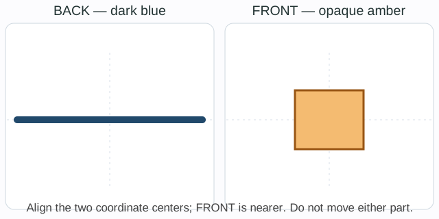
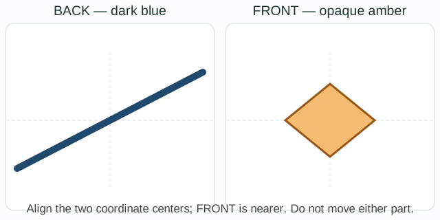
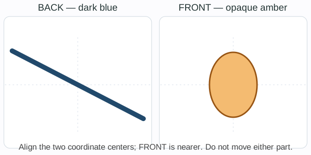
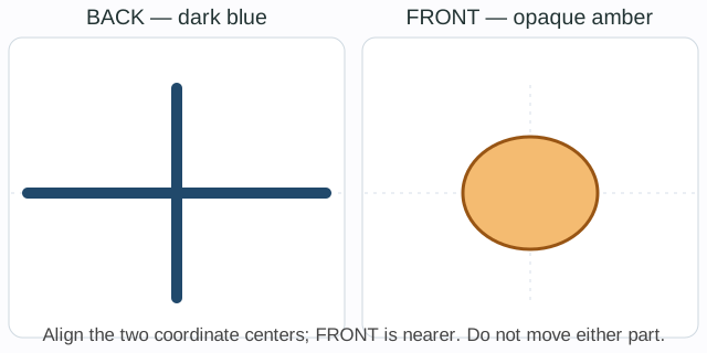
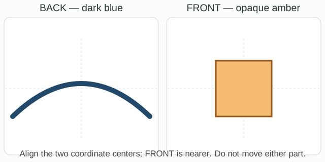
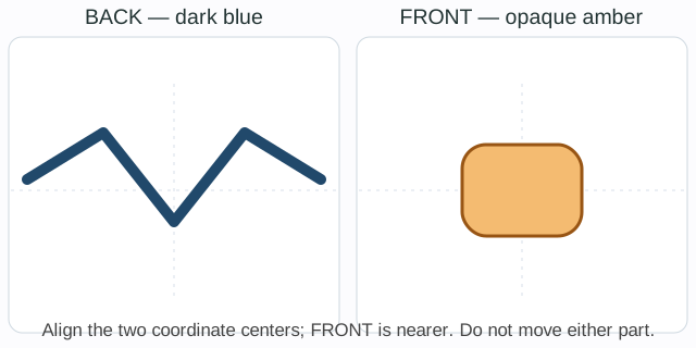
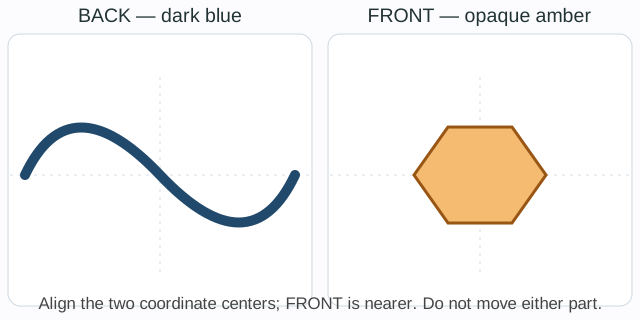
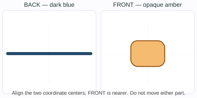
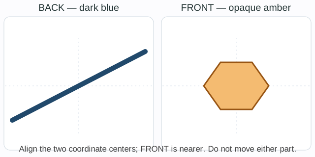
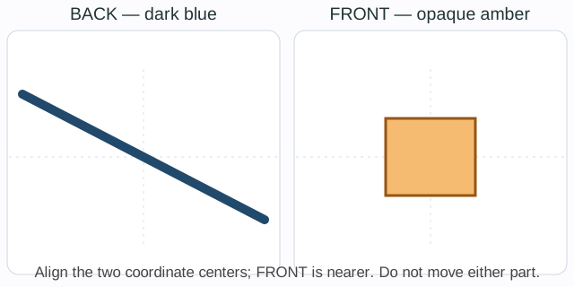
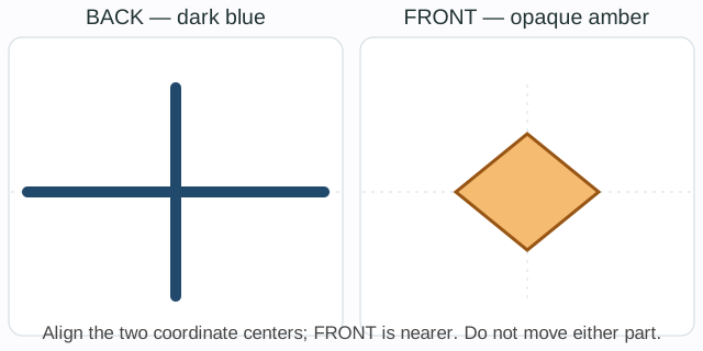
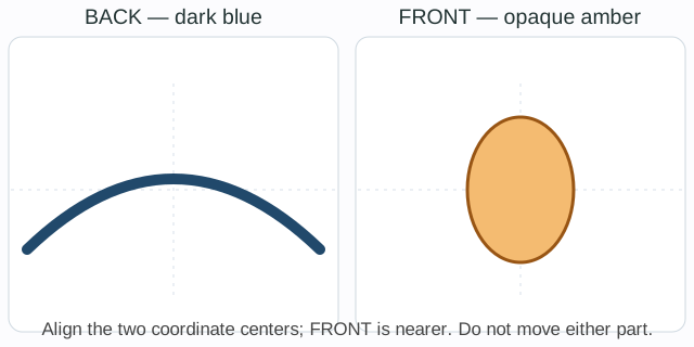
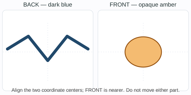
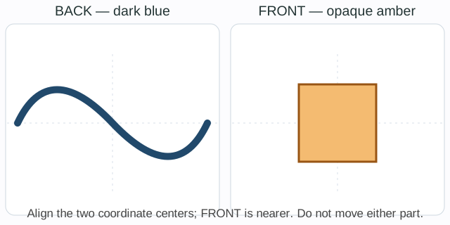
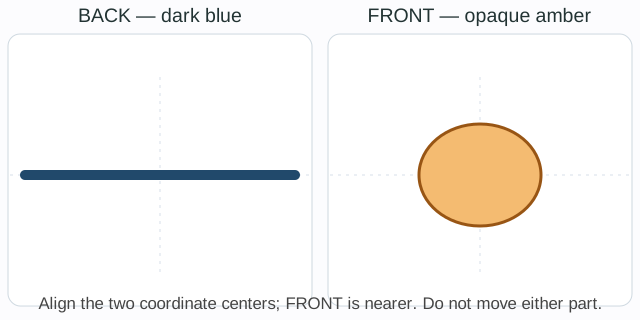
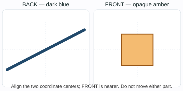
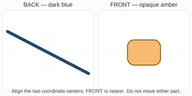
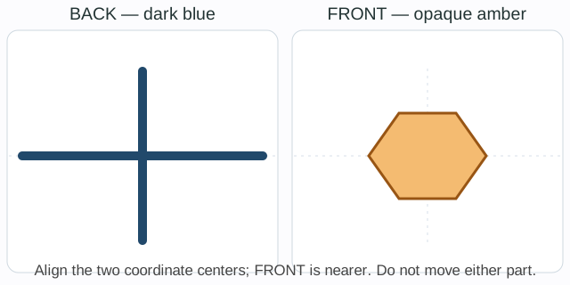
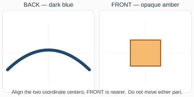
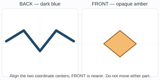
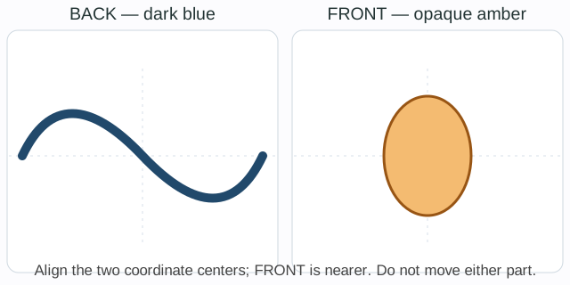
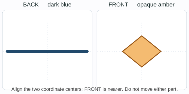
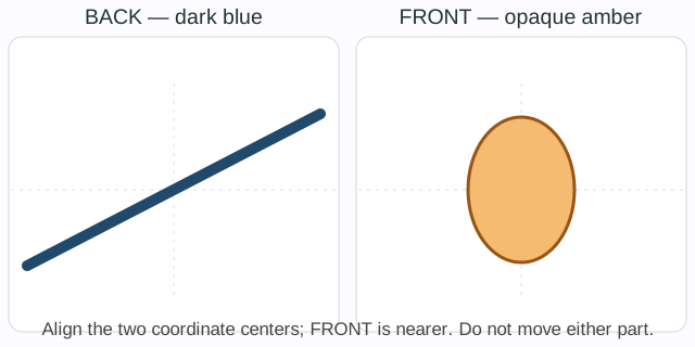
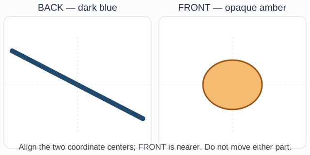
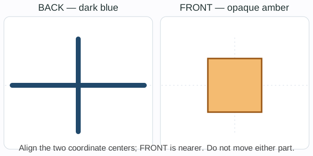
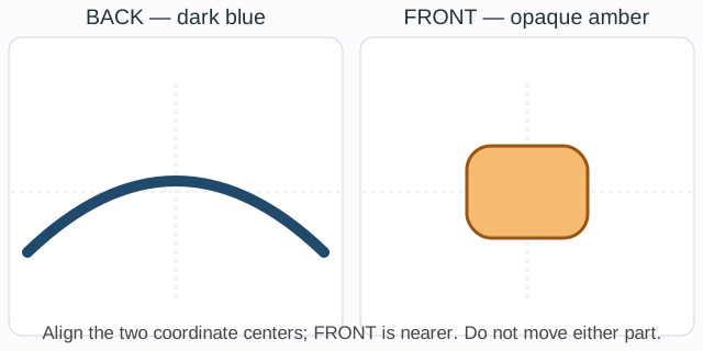
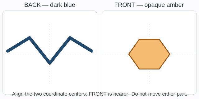
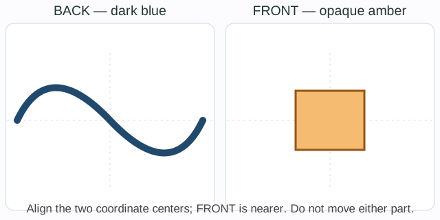
 English ▾