 ASVAB Camp
Lesson goals and EI scope
By the end of this lesson you should be able to explain what resistance is and how it differs from resistivity, sort materials into conductors, insulators, ionic conductors, and semiconductors, and calculate resistance with
using correct units.
You will also predict how length, cross-sectional area, and temperature change a wire's resistance, describe common resistor types, and recall the safe way to use an ohmmeter. These ideas appear throughout the Electronics Information subtest.
What electrical resistance means
Resistance is the opposition a material or component presents to the flow of electric current. When a voltage pushes charge through a path, some of the electrical energy is converted into heat as the moving charges interact with the material.
Think of a flashlight bulb and a short piece of thick copper wire placed on the same battery. The bulb strongly limits the current and glows hot; the copper hardly limits it at all. The bulb has the much larger resistance.
Do not confuse current, voltage, and resistance
These three quantities are related but are not the same thing. Voltage, measured in volts, is the electrical push, or energy per unit charge, between two points. Current, measured in amperes, is the rate at which charge flows past a point. Resistance, measured in ohms, describes how strongly a path opposes that flow.
A quick check: voltage is something you apply across a part, current is something that flows through it, and resistance is a property of the part itself.
The ohm and its unit symbol
The SI unit of resistance is the ohm, written with the Greek capital letter omega, . One ohm is the resistance that lets exactly one ampere flow when one volt is applied across it.
Do not mix up the symbols: V stands for volt, A for ampere, W for watt, and for ohm.
Resistance in the V–I–R relationship
For many components, the current is directly proportional to the applied voltage. The constant that links them is the resistance:
Here R is resistance in ohms, V is voltage in volts, and I is current in amperes. A heater element that draws 4 A from a 120 V supply has
At a fixed voltage, a larger R means a smaller current, and a smaller R means a larger current.
The physical origin of resistance in metals
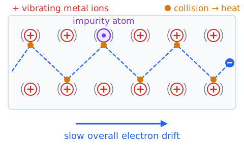
A metal contains a sea of loosely held electrons that can drift through a lattice of positive ions. When a voltage is applied, those electrons gain a slow overall drift in one direction. Along the way they keep scattering off vibrating ions, impurity atoms, and defects in the crystal.
Each collision hands some of the electrons' energy to the lattice, which shows up as heat. The more often scattering happens, the higher the resistance. This picture explains why impurities and higher temperatures usually raise a metal's resistance.
Good conductors: practical examples
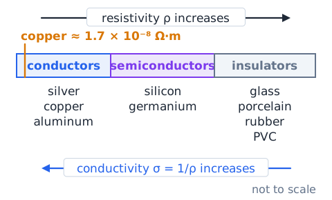
A conductor allows current to pass easily because it has many charge carriers that are free to move. Silver is the best ordinary metal conductor, with copper a close second. Copper is the standard choice for building wiring, extension cords, and motor windings because it conducts well, bends easily, and costs far less than silver.
Aluminum is used in overhead power lines because it is light. Gold is used as a thin plating on connectors, mainly because it resists corrosion rather than because it is the best conductor.
Insulators: practical examples
An insulator has very few free charge carriers, so it has a very high resistivity and allows only a tiny current under normal conditions. Common insulators include dry glass, porcelain and other ceramics, rubber, many plastics such as PVC, dry wood, and air.
You see them wherever current must be kept on its intended path: plastic jackets on wires, ceramic insulators on utility poles, and rubber or plastic handles on tools. Notice the word "dry." Moisture, dirt, and contamination on a surface can create a leakage path and reduce how well an insulator does its job.
Semiconductors occupy a controllable range
Semiconductors such as silicon and germanium have resistivities between those of good conductors and good insulators. What makes them valuable is that their conductivity can be controlled.
Adding tiny, carefully chosen amounts of impurity atoms, a process called doping, can raise conductivity enormously. Light and temperature also affect them: unlike metals, a pure semiconductor usually conducts better as it warms. These controllable properties are the basis for diodes, transistors, solar cells, and integrated circuits.
Electrolytes and ionic conductors
In metals, the moving charges are electrons. In an electrolyte, the moving charges are ions, which are atoms or molecules carrying a net positive or negative charge. When table salt dissolves in water, it separates into sodium and chloride ions that can drift toward opposite electrodes.
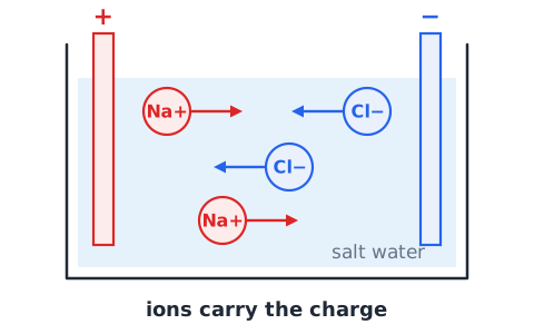
Very pure water has few ions and conducts poorly. Tap water, sweat, and seawater contain dissolved salts, so they conduct much better. That is one reason wet skin and wet surfaces make electric shock more dangerous. Battery electrolytes are another example of ionic conduction.
Electric conductivity and resistivity
Resistivity, symbol (the Greek letter rho), measures how strongly a material opposes current, independent of the object's size or shape. Its SI unit is the ohm-meter, .
Conductivity, symbol (sigma), is simply its reciprocal,
and is measured in siemens per meter. A material with low resistivity has high conductivity. Copper has a resistivity near , while glass is many trillions of times larger.
Resistance is not the same as resistivity
Resistivity belongs to a material. Resistance belongs to a particular object. Every copper wire at the same temperature has the same resistivity, but a long, thin copper wire has a larger resistance than a short, thick one.
A useful comparison is density versus weight. Steel always has the same density, but a steel beam weighs more than a steel nail. In the same way, resistivity tells you about the material, while resistance also depends on length and cross-sectional area. Resistance is in ohms; resistivity is in ohm-meters.
The length rule for uniform wires
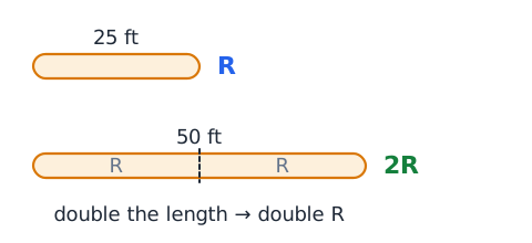
For a uniform wire of one material at a fixed temperature, resistance is directly proportional to length. Double the length and the resistance doubles; cut the length to one third and the resistance falls to one third.
The reason is that a longer wire is like several shorter pieces placed end to end, and their resistances add. A 50 ft extension cord therefore has about twice the conductor resistance of an otherwise identical 25 ft cord.
Cross-sectional area changes resistance
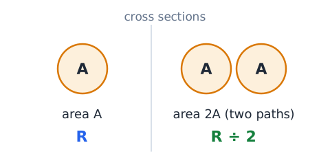
Cross-sectional area is the area of the face you would see if you sliced straight across the wire. For a uniform wire, resistance is inversely proportional to that area.
A wire with twice the area is like two identical wires side by side, giving the charge two equal paths, so the resistance is cut in half. This is why heavy-current circuits, such as an electric range or a car's starter motor, use thick conductors: a larger area means lower resistance and less heating.
The resistivity-length-area model
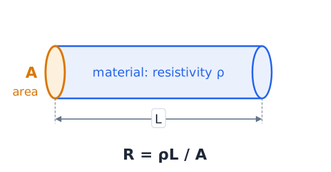
The length and area rules combine with the material's resistivity into one formula for a uniform conductor:
R is resistance in ohms, is resistivity in , L is length in meters, and A is cross-sectional area in square meters. The units check out:
Resistance goes up with and L and goes down as A increases.
Thickness means area, not just diameter
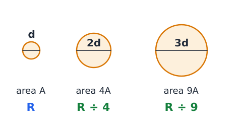
Wires are usually described by diameter, but the formula uses area. For a round wire,
so area depends on the square of the diameter. If the diameter doubles, the area becomes
times larger and the resistance drops to one fourth. If the diameter triples, the area grows 9 times and the resistance falls to one ninth. Always square a diameter ratio before using it.
Length and area changes can cancel
Because R depends on the ratio , changes in length and area can offset each other. For the same material,
If a wire becomes five times longer and also five times larger in area, the ratio is
so the resistance is unchanged. Any time length and area change by the same factor, the effects cancel.
Compare wires before doing arithmetic
Many test questions about wires can be answered by reasoning before calculating. First list what stays the same: material, temperature, and perhaps length or area. Then note only what changes.
Ask two questions. Is the path longer or shorter? Longer raises resistance. Is the path wider or narrower? Wider lowers it. If both changes push resistance the same way, the answer is a larger change; if they push opposite ways, they may partly or fully cancel. Doing this first lets you reject answer choices that move in the wrong direction.
Temperature usually increases metallic resistance
For most pure metals, resistance rises as temperature rises. Warmer atoms in the lattice vibrate more strongly, so the drifting electrons scatter more often and lose energy more quickly.
Near room temperature the change in copper is modest, roughly 0.4 percent per degree Celsius, but it adds up. A copper motor winding that warms by 50 degrees Celsius during operation has about 20 percent more resistance than when it was cold. Test questions usually say "assume constant temperature" to remove this effect.
Temperature coefficients are material-dependent
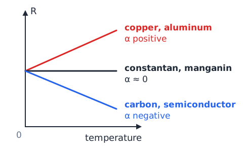
The temperature coefficient of resistance, written (alpha), tells how much resistance changes per degree for each ohm of starting resistance. Pure metals such as copper and aluminum have a positive coefficient of about 0.004 per degree Celsius.
Certain alloys, such as constantan and manganin, are designed to have a coefficient close to zero, so their resistance barely changes with temperature. Carbon and most semiconductors have a negative coefficient over normal ranges: their resistance drops as they warm. The sign and size depend on the material.
Why a hot incandescent filament behaves differently
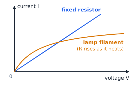
An incandescent lamp uses a thin tungsten filament that runs at well over 2,000 degrees Celsius. Because tungsten's resistance rises sharply with temperature, a hot filament may have more than ten times the resistance it has when cold.
That has two effects. At the moment of switching on, the cold filament draws a large surge of current, which is why bulbs often fail at turn-on. And because R changes as the filament heats, its current is not proportional to voltage, so a lamp does not follow a single fixed-resistance line.
High resistance does not mean no current
A large resistance reduces current; it does not automatically stop it. If a voltage is applied across a path, some current flows unless the resistance is truly infinite.
The human body is a good warning. Dry skin can have a resistance of many thousands of ohms, yet a high enough voltage can still push a dangerous current through it. A small leakage current through damp insulation is another example. Treat "high resistance" as "small current for a given voltage," not as "safe" or "zero."
Zero resistance is also an idealization
Circuit diagrams usually draw connecting wires as if they had zero resistance. That is a convenient simplification, not a physical fact. Every ordinary wire, connector, switch contact, and fuse has some small resistance.
In most low-current circuits these values are tiny compared with the components, so ignoring them causes little error. With long runs or large currents, though, wire resistance matters: it causes voltage drop and heating. Only a superconductor below its critical temperature actually reaches zero resistance.
Resistors have a deliberate circuit role
A resistor is a component made to provide a specific, known resistance. Designers use resistors on purpose to limit current, for example to keep an LED from burning out, to divide a voltage into smaller parts, to set bias levels in transistor circuits, and to convert a current into a voltage that can be measured.
As current flows through a resistor, it opposes that current and converts electrical energy into heat. A resistor does not create charge or store energy; it controls how current and voltage are distributed in a circuit.
Carbon-film, metal-film, and wirewound resistors
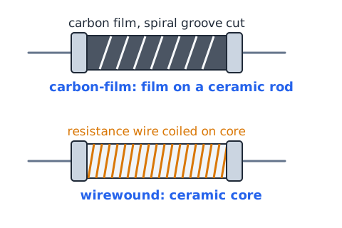
Carbon-film resistors are made by coating a ceramic rod with a thin carbon layer and cutting a spiral groove into it to set the value. They are inexpensive and common in general circuits.
Metal-film resistors use a thin metal alloy layer instead; they are more precise, more stable with temperature, and produce less electrical noise. Wirewound resistors consist of resistance wire wrapped around a ceramic core. They can handle much more power and heat, which makes them suitable for power supplies and load banks.
Why some resistor alloys are useful
Heating elements and wirewound resistors use alloys such as nichrome, a nickel-chromium mix, rather than copper or silver. Nichrome's resistivity is roughly 60 times that of copper, so a practical length of wire can provide the resistance needed to produce heat.
A silver or copper heater wire would need to be extremely long or extremely thin to reach the same resistance. Nichrome also resists oxidation when red hot. Alloys such as manganin are chosen instead for precision resistors because their resistance stays nearly constant with temperature.
Fixed and variable resistors
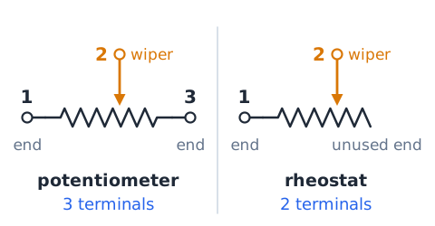
A fixed resistor has one set value that does not change in normal use. A variable resistor lets the resistance be adjusted. A potentiometer has three terminals: two at the ends of a resistive track and a movable wiper that slides along it. It is often used as a volume or brightness control.
A rheostat uses just two terminals, one end and the wiper, to vary the resistance in series with a load. Small trimmer potentiometers are set once with a screwdriver during calibration and then left alone.
Thermistors and light-dependent resistors
Some resistors are designed to change value in response to their surroundings. A thermistor's resistance changes strongly with temperature. The common NTC type has a negative temperature coefficient, so its resistance falls as it warms; PTC types rise. Thermistors are used in thermostats, battery chargers, and inrush-current limiters.
A light-dependent resistor, or photoresistor, has high resistance in darkness and much lower resistance in bright light. A typical use is an automatic night light that switches on at dusk.
Power dissipation in a resistor
A resistor converts electrical energy to heat at a rate called power, measured in watts. Three equivalent forms are:
Choose the one that uses the quantities you know. For a 100 resistor carrying 0.2 A,
That heat must leave the part, or its temperature keeps rising.
Resistor ratings and overheating
Every resistor has a power rating, such as 1/4 W, 1/2 W, or 5 W, which is the most heat it can safely shed. Physically larger resistors generally have higher ratings. Good practice is to choose a rating at least about twice the expected power.
Example: 12 V across a 47 resistor gives
A 1/4 W part would overheat, discolor, and could fail open or start a fire; a rating of about 6.2 W or more (for example 10 W) is appropriate.
Ohmmeter measures resistance
An ohmmeter is the instrument made to measure resistance; on a digital multimeter it is the setting marked with . The meter sends a small known current from its own internal battery through the part and calculates resistance from the resulting voltage.
Because it supplies its own current, the circuit being tested must be switched off and de-energized first. Measuring resistance in a live circuit gives false readings and can damage the meter. By contrast, an ammeter measures current and a voltmeter measures voltage.
Why parallel paths matter when measuring
An ohmmeter reads the resistance of everything connected between its two probes. If a resistor is still soldered into a circuit, other components may form a parallel path around it. The meter's current then splits among those paths, and the reading shows their combined resistance, which is lower than the resistor's own value.
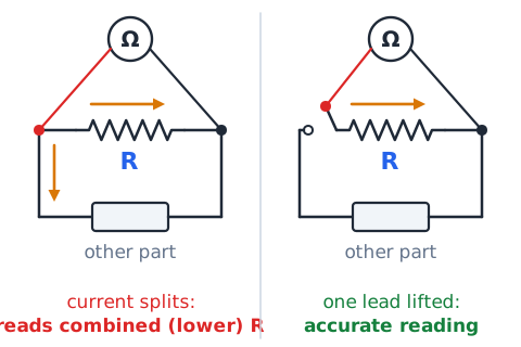
For an accurate reading, disconnect at least one lead of the part so that it is isolated, then measure. Holding both probe tips with your fingers adds your body as another parallel path.
The resistance of connections and contacts
Wherever two conductors meet, at a screw terminal, a plug blade, a crimp, or a switch contact, there is some contact resistance. In a clean, tight joint it is tiny. A loose screw, corrosion, or a pitted switch contact can raise it greatly.
Because all of the circuit current passes through that small spot, even a modest resistance produces concentrated heat (
). This is why a loose outlet connection can feel warm, discolor the plastic, and become a fire hazard, even though the wire itself is sized correctly.
Copper versus aluminum: not just resistivity
Aluminum's resistivity is about 1.6 times copper's, so an aluminum conductor must be larger to carry the same current with the same resistance. Even so, aluminum weighs much less and costs less, which is why it is used in long overhead transmission lines and some large service cables.
Aluminum also has drawbacks: it forms an oxide film on its surface, expands more with heat, and can loosen at terminals over time. Connections for aluminum wire must use devices rated for it. Material choice balances resistance, weight, cost, strength, and reliability.
Wire gauge and conductor size
In the United States, wire size is commonly stated in the American Wire Gauge (AWG) system. The numbering runs backward from what many people expect: a larger gauge number means a thinner wire. A 12 AWG wire is thicker than a 14 AWG wire and has less resistance per foot.
Thicker wire can carry more current without overheating, which is why circuits with larger breakers require heavier gauge wire. Moving three gauge numbers smaller roughly doubles the cross-sectional area.
Cross-sectional area versus exposed surface
The area that matters in
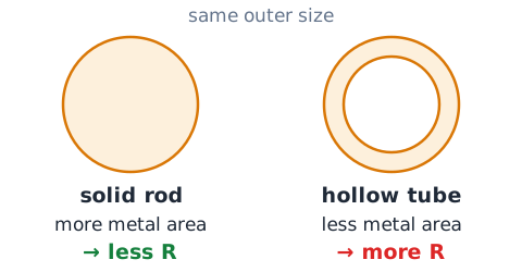
is the cross section, the area of a slice straight across the conductor, not the outside surface you could paint. For steady direct current, the current uses the whole cross section evenly.
So a hollow tube and a solid rod of the same outer size do not have the same resistance: the tube has less metal in its slice and therefore more resistance. At very high frequencies alternating current tends to crowd near the surface, but that effect is beyond basic EI questions.
Electrical resistivity depends on temperature
Resistivity is a material property, but it is quoted at a particular temperature, often 20 degrees Celsius. For a metal over a moderate range, it changes approximately as
where is the value at the reference temperature, is the temperature coefficient, and is the change in temperature. The same form applies to the resistance of a part whose dimensions barely change. For semiconductors and carbon, is negative.
Insulators can break down
No insulator blocks current under every condition. If the voltage across it becomes high enough, the electric field can tear electrons loose and create a conducting path. This is called dielectric breakdown, and the voltage at which it happens depends on the material and its thickness.
Lightning is air breaking down. A spark plug works by deliberately breaking down the air gap. Heat, aging, cracks, moisture, and contamination all lower breakdown voltage, which is why insulation is rated for a maximum voltage and why worn cords must be replaced.
Superconductors are a special case
A superconductor is a material whose resistance drops to exactly zero when it is cooled below a certain critical temperature. In that state, a current can circulate in a loop for a very long time without any loss to heat.
Most superconductors must be chilled with liquid helium or liquid nitrogen, which is expensive and complex. They are used where enormous currents and strong magnetic fields are required, such as in hospital MRI magnets and particle accelerators. Ordinary copper wiring is never a superconductor.
Resistor notation: Ω, kΩ, and MΩ
Resistances cover a huge range, so metric prefixes are used. One kilohm is a thousand ohms and one megohm is a million ohms:
So 2.2 k is 2,200 , and 0.5 M is 500,000 . Schematics sometimes write 4k7 to mean 4.7 k.
Resistance and ideal wires in diagrams
In a schematic, a resistor is drawn as a zigzag line or, in international style, a small rectangle, labeled with its value. The plain straight lines connecting parts represent ideal wires with no resistance.
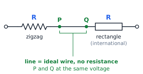
That convention means that any two points joined only by a line are at the same voltage. Voltage drops appear only across the drawn components. If a problem wants you to account for wire resistance, it will normally show the wire as its own resistor or give its value in the text.
Distinguish an open circuit from a short circuit
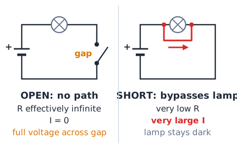
An open circuit is a break in the path, such as an open switch, a blown fuse, or a cut wire. Its resistance is effectively infinite, so no current flows through it, though the full source voltage may appear across the gap.
A short circuit is an unintended path with very low resistance that bypasses the load. Because the resistance is so small, the current can become very large, causing heating, damage, or fire until a fuse or breaker opens. Open means no path; short means too easy a path.
Equivalent resistance: a brief preview
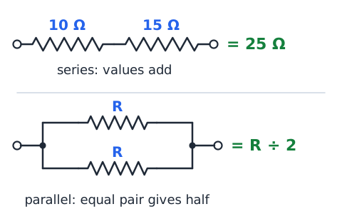
When several resistors are connected together, they can be replaced in analysis by one equivalent resistance. In series, connected end to end with one path, the values add: 10 and 15 in series act like 25 .
In parallel, connected across the same two points with separate paths, the equivalent is smaller than the smallest branch, because extra paths make it easier for current to flow. Two equal resistors in parallel give half of one resistor's value. Later lessons develop these rules fully.
The water-pipe analogy and its limits
A common analogy compares a circuit to water in pipes: voltage is like water pressure, current is like flow rate, and resistance is like a narrow or long pipe that restricts flow. A narrow, long pipe passes less water, just as a thin, long wire has more resistance.
The analogy breaks down in places. Electric charge does not spill out of a cut wire the way water leaks, the wire does not need to be "full" first, and electrical energy travels through fields almost instantly. Use it for intuition, not for exact rules.
Why energy is not “used up” in a wire
Charges are not consumed in a circuit. In a simple loop, the current leaving the battery equals the current returning to it. What changes is energy: each coulomb of charge gives up energy as it passes through resistance.
In a resistor or heater, that energy becomes heat or light. In a good connecting wire, the resistance is small, so only a little energy is converted there. That is why the cords stay cool while the heater element glows. Saying "current is used up" is a common error.
Controlling variables in a resistance experiment
To find how one factor affects resistance, change only that factor and hold the others constant. To study length, use wires of the same metal, the same cross-sectional area, and the same temperature, and vary only the length.
If a student changes both length and diameter at once, any difference in resistance cannot be credited to either one alone. Keeping the test current small also helps, because a large current heats the wire and changes its resistance during the measurement.
Read a resistance-versus-length graph
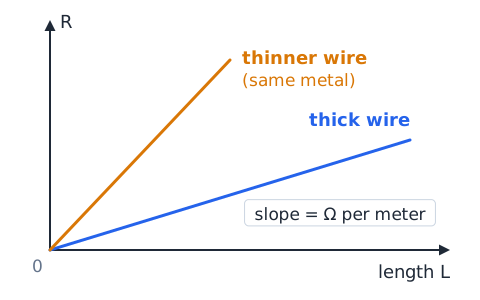
If resistance is plotted on the vertical axis against length on the horizontal axis for one uniform wire, the points fall on a straight line through the origin. That straight line confirms that resistance is directly proportional to length.
The slope equals resistance per unit length, in ohms per meter. A thinner wire of the same metal gives a steeper line, because each meter has more resistance. A higher-resistivity metal of the same size also gives a steeper line.
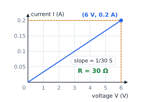
Read a current-versus-voltage graph
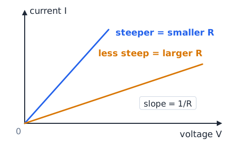
For an ohmic resistor, a graph of current I (vertical) against voltage V (horizontal) is a straight line through the origin. Its slope is
which has units of siemens. A steeper line means a smaller resistance. If the axes are swapped, voltage vertical and current horizontal, the slope equals R itself.
Resistance of a circuit versus resistance of a device
Be clear about whose resistance a question is asking for. A device such as a lamp has its own resistance. The whole circuit includes that lamp plus the wires, the switch, connections, and even the internal resistance of the battery.
Usually the device dominates and the rest is small. When an answer depends on the total, though, every part in the current path counts. If a question says "ideal wires" or "ideal source," it is telling you to ignore those extra parts.
How to use ratios without a calculator
Instead of plugging in resistivity values, write the new resistance as the old value times a factor for each change:
Note that the area ratio is upside down. Example: a 10 wire with length tripled and area doubled becomes
Practice diagnosing everyday high-resistance symptoms
Unwanted resistance often shows up as heat or voltage loss. A plug that feels hot where it enters the outlet may have a worn, loose contact. Dim headlights that brighten when a battery cable is wiggled point to a corroded terminal. A long, thin extension cord feeding a space heater may run warm because its conductors are too small for the current.
In each case, a small resistance in the main current path wastes power as heat. The fix is to clean, tighten, or replace connections, or to use a heavier gauge conductor.
Unplugged and de-energized are not synonyms
Before measuring resistance or touching conductors, the circuit must be fully de-energized, which means every source of electrical energy is removed and verified absent. Unplugging one cord may not be enough.
Equipment may have a second supply, a backup battery, or capacitors that hold a charge for some time after power is removed. In workplaces, lockout and tagout procedures are used so that no one can restore power by mistake. Qualified workers confirm zero voltage with a meter that has been checked on a known live source.
Common mistake: copper is not perfect
Copper is an excellent conductor, but it is not a zero-resistance conductor. Long runs of copper wire carrying heavy current produce measurable voltage drop and heat, which is why electricians increase wire size for long circuits.
The mistake is to assume that any copper wire has no resistance in a calculation. Treat copper as ideal only when the problem tells you to or when its resistance is clearly tiny compared with the rest of the circuit.
Common mistake: confusing area and length
Length and area affect resistance in opposite directions, and students sometimes swap them. Resistance goes up with length and down with area:
A second error is to treat a diameter change as an area change. If a wire's diameter is cut in half, the area becomes one fourth, so resistance becomes four times larger, not two times. Square the diameter ratio first.
Common mistake: resistance and power
It is tempting to think a larger resistance always heats more. It depends on what is held fixed. At the same current,
so the larger resistance dissipates more power.
At the same voltage,
so the smaller resistance dissipates more power, because it draws more current. Household appliances run at a fixed voltage, so a high-wattage heater actually has a lower resistance than a low-wattage lamp.
Exam strategy: read fixed conditions first
Before choosing an answer, find the phrases that tell you what is held constant: "same material," "same length," "same temperature," "at the same voltage," or "at the same current." These conditions decide which relationship applies.
For example, comparing two resistors' power at a fixed voltage leads to a different answer than comparing them at a fixed current. Underline the fixed conditions, identify the one quantity that changes, and only then predict the direction of the result.
Exam strategy: solve from physical meaning
When numbers look confusing, picture the wire. A longer path gives more opposition. A wider path gives less. A hotter metal gives more. A material with higher resistivity gives more.
Decide whether the answer should go up, go down, or stay the same, then eliminate any choice that goes the wrong way. Often only one choice remains, and you can confirm it with a quick ratio.
Compare identical copper wires
Problem: A 5 m copper wire measures 2 . A second copper wire with the same area and temperature is 15 m long. Find its resistance.
Only length changes, by a factor of
Answer: 6 .
Make a conductor twice as wide in area
Problem: A bus bar has a resistance of 14 milliohms. It is replaced by a bar of the same metal and length but with twice the cross-sectional area. Find the new resistance.
Doubling the area gives two equal paths side by side, so resistance is divided by 2. Answer: the new bar measures 7 milliohms.
Competing length and area changes
Problem: A 5 wire is replaced by one of the same metal that is 3 times as long with 1.5 times the area.
Length pushes R up by 3; area pushes it down by 1.5.
Answer: 10 .
Calculate resistance from V and I
Problem: A soldering iron element draws 0.5 A when 24 V is applied. What is its resistance at operating temperature?
Answer: 48 . Note that dividing current by voltage would give the wrong quantity.
Convert kilo-ohms
Problem: Express 4.7 kilohms in ohms, and 820 ohms in kilohms.
Kilo means one thousand. Multiply by 1,000 to go from kilohms to ohms: 4.7 kilohms equals 4,700 ohms. Divide by 1,000 to go the other way: 820 ohms equals 0.82 kilohms.
Use diameter squared
Problem: A 3 wire is replaced by one of the same metal and length whose diameter is half as large.
Area scales with diameter squared:
Resistance scales inversely with area, so
Answer: 12 .
Read a length graph
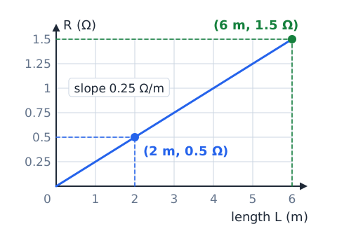
Problem: A graph of R versus length for a uniform wire is a straight line through the origin and passes through (2 m, 0.5 ). Find R for 6 m.
Slope:
Then
Read the I–V slope
Problem: An I-versus-V line for a resistor goes through the origin and the point (6 V, 0.2 A). Find R.
R is the reciprocal of the slope, so R = 30 .
Compute proportional material effect
Problem: A wire of metal A measures 2 . A wire of identical length, area, and temperature is made of metal B, whose resistivity is 1.5 times that of A.
With size held fixed, R is proportional to :
Answer: 3 .
Ohmmeter ranges
Problem: A technician tests a resistor marked 47 kilohms on a manual-range meter set to 200 ohms, and the display shows OL (overload). What should she do?
OL means the value is above the selected range, not that the part is open. With the circuit de-energized and the part isolated, she should switch to the 200 kilohm range. A reading near 47 then confirms the marked value.
Find resistivity with SI units
Problem: A 10 m wire with area measures 2 . Find .
Fixed-voltage power comparison
Problem: Resistors of 6 and 12 are each placed across their own 12 V source. Which dissipates more?
At fixed voltage, the smaller resistor dissipates twice as much.
Fixed-current power comparison
Problem: A constant 3 A flows through a 2 part and, separately, through a 5 part. Compare power.
At fixed current, the larger resistance dissipates more.
A temperature-coefficient estimate
Problem: A copper coil measures 50 at 20 degrees Celsius. Take
per degree Celsius and ignore size changes. Estimate R at 70 degrees Celsius.
The temperature rise is 50 degrees, so
Guided drill: classify the material
Classify each material as a conductor, insulator, semiconductor, or ionic conductor.
Silver? Conductor; it is the best ordinary metal conductor.
Dry porcelain? Insulator.
Silicon? Semiconductor; its conductivity is controlled by doping.
Seawater? Ionic conductor; dissolved salt ions carry the charge.
Dry PVC plastic? Insulator.
Guided drill: apply length and area factors
Start each from a 12 wire of fixed material and temperature.
Length doubled? 24 .
Area tripled? 4 .
Length and area both quadrupled? Still 12 .
Diameter doubled? Area becomes 4 times larger, so 3 .
Guided drill: distinguish units
Give the unit for each quantity.
Resistance? Ohm, .
Resistivity? Ohm-meter, m.
Conductance (1/R)? Siemens, S.
Conductivity? Siemens per meter.
Current? Ampere, A.
Guided drill: decide the correct graph slope
On a graph of V (vertical) versus I (horizontal) for an ohmic resistor, what is the slope? R, in ohms.
On a graph of I (vertical) versus V (horizontal), what is the slope? 1/R, in siemens.
Two I-versus-V lines: which has more resistance? The less steep one.
Guided drill: spot an unsafe assumption
"The switch is off, so the equipment is safe to work on." Unsafe: other sources or stored charge may remain; verify de-energization.
"My gloves are rubber, so I cannot be shocked." Unsafe: insulation can be damaged, wet, or under-rated.
"I can check this resistor with the power on." Unsafe and inaccurate: ohmmeters need a de-energized circuit.
Guided drill: resolve a mixed-variable question
A 4 wire is replaced by one with twice the resistivity, half the length, and half the area. What is the new resistance?
Resistivity doubles R, halving length halves it, and halving area doubles it. Net factor: 2. Answer: 8 .
Quick review checklist
Resistance is opposition to current, measured in ohms () with an ohmmeter on a de-energized, isolated part.
Resistivity is a material property in m. R rises with length and resistivity and falls with area; a diameter ratio must be squared. Metals gain resistance when heated. Conductors such as copper carry current easily, insulators such as dry ceramic resist it until breakdown, ions carry current in salt water, and semiconductors are controllable. An open circuit has effectively infinite resistance. At fixed voltage the smaller R dissipates more power; at fixed current the larger R does.
 English ▾