 ASVAB Camp
What woodworking questions actually test
The Shop Information portion of the ASVAB tests recognition of tools, shop terminology, materials, and sensible working practices. A question may describe a desired result and ask you to identify the appropriate tool rather than ask for a long construction procedure. Read the task first: separating material, flattening a face, joining pieces, boring a hole, and smoothing a surface are different goals. The best answer normally matches the operation and respects a tool’s intended use. Real shop work additionally requires training, manufacturer instructions, and applicable safety controls.
Wood as an anisotropic material
Wood has grain because much of its structure runs along the tree’s growth direction. It typically behaves differently along the grain than across it; for example, splitting often follows weak paths along fibers. A cutting tool designed to follow grain is not necessarily the best for cutting across those fibers. Grain also affects how a hand plane behaves and whether a fastener can split an edge. Distinguish solid lumber, plywood, particleboard, and fiberboard rather than assuming all panels respond alike to cutting, moisture, or fastening.
Grain, growth rings, and working faces
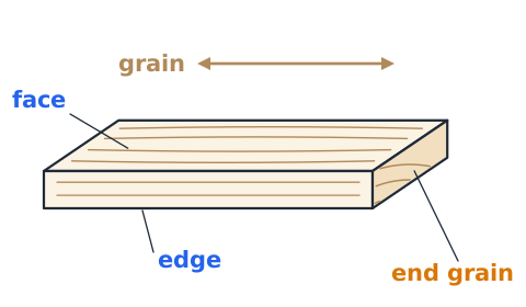
Look at the lengthwise grain direction before selecting a saw. End grain shows the cut ends of fibers and can demand different cutting and finishing methods from face grain. A long board may have a face, edge, and end; keeping those surfaces distinct helps interpret a shop drawing. Growth rings may explain visible figure, but appearance alone cannot prove a board’s strength. On the exam, terms such as “with the grain,” “across the grain,” and “square to the face” usually tell you which operation or reference surface matters.
Nominal versus actual lumber dimensions
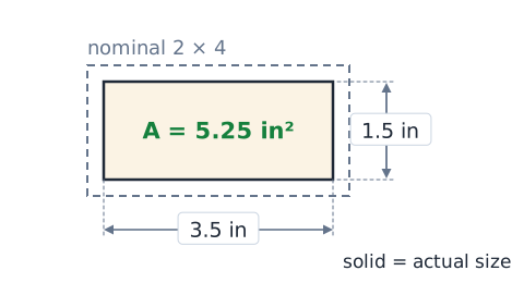
In common North American dimensional softwood, the nominal trade size can be larger than the finished actual size. A nominal 2 × 4 is commonly approximately 1.5 × 3.5 inches after surfacing, although actual sizes vary by product and condition. For an arithmetic question, use dimensions stated in the problem rather than relying on a naming convention. If a shelf must fit a real opening, measuring the actual workpiece is more reliable than guessing from the label. Do not confuse a board’s length, width, and thickness.
Plywood versus particleboard
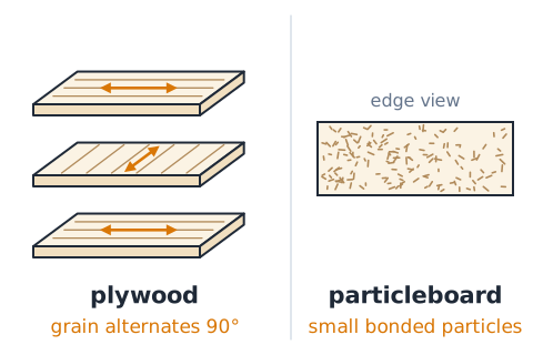
Plywood consists of bonded veneer layers, usually with neighboring grain directions alternating; this construction gives useful dimensional properties and helps resist some splitting modes. Particleboard uses small wood particles bonded with resin and behaves differently near edges and around fasteners. Medium-density fiberboard uses wood fibers and tends to machine uniformly but can generate fine dust. Material choice depends on load, moisture, edge finishing, and manufacturer instructions. Exam distractors may claim that every wood-based sheet is natural solid lumber: that is incorrect.
Reference face, edge, and square
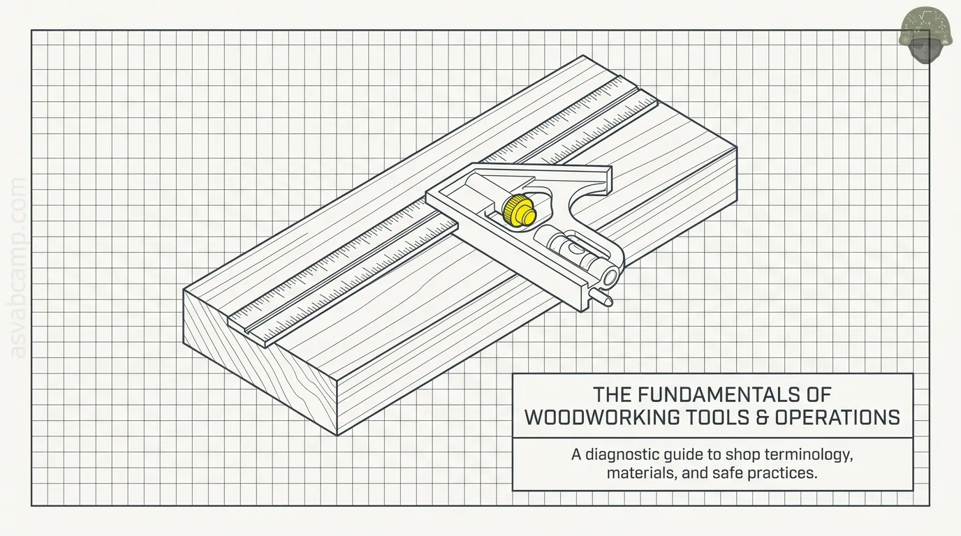
Accurate layout starts with a reliable reference face and edge, often called datum surfaces. A try square checks or marks a nominal 90-degree relationship between a face and an edge; it does not measure a curved line. Mark from the same reference edge whenever possible to avoid stacking small errors. A combination square may add a sliding head and measuring rule. If a cut is square to one side but that side is already out of square, the cut can reproduce the initial error. Choose and verify the reference before marking.
Measuring tapes and folding rules
A tape measure is convenient for lengths and ordinary layout but a damaged hook, skewed tape, or poorly aligned sight line can cause reading error. Folding rules provide rigid segments for some situations. Keep the measuring tool straight along the intended dimension and write down the value with units. Read mixed-number fractions carefully: 3 5/8 inches is not 3.58 inches. For close machining tolerances, a tape is not a substitute for a suitable precision measuring device.
Marking knife, pencil, and chalk line
A sharp marking knife makes a fine reference line for precise hand-tool work; a pencil is versatile but leaves a mark with some width. A chalk line quickly marks a long straight layout across sheet goods when properly snapped. Select the mark appropriate to the surface and required accuracy, then cut on the specified waste side of the line. The line represents a boundary, not a region in which saw kerf can be ignored. Marking devices help indicate geometry; they do not verify that the reference edge is straight.
The cut list and waste allowance
A cut list records parts, quantities, finished dimensions, and often material or orientation. Before cutting stock, include the width of material removed by the saw blade, called the kerf. A sequence of equal pieces cannot consume a board’s entire length if every separation removes material. Plan the cutting order to reduce waste while honoring grain orientation, defects, clamping, and available machine capacity. For exam arithmetic, determine exactly how many cuts are required rather than assuming there is always one cut per finished piece.
Understanding saw kerf
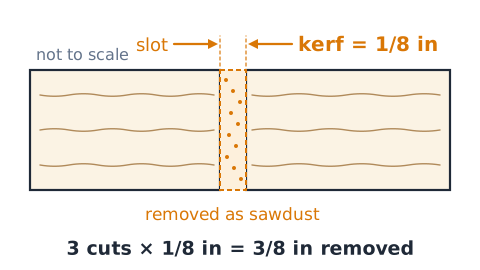
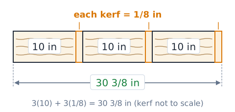
Kerf is the width of the slot removed by a saw, not the thickness of the uncut board. With a 1/8-inch kerf, three full separation cuts remove 3/8 inch of the stock's length. Tooth set, blade geometry, and setup affect actual kerf, so the stated problem value takes priority over a general assumption. For a simplified planning calculation, total required length equals the sum of cut-piece lengths plus the kerf losses of the cuts made on the available stock.
Rip cut and crosscut
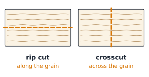
A rip cut runs broadly parallel to the lengthwise grain of solid wood; a crosscut goes across it. The names describe orientation relative to the fibers, not merely whether the board is long or short. A ripsaw uses tooth geometry adapted for cutting along fibers; a crosscut saw severs fibers across their direction. Sheet goods may not present one continuous grain direction, so follow the cutting tool and blade recommendations for that material. On the exam, “with the grain” strongly suggests ripping and “across the grain” suggests crosscutting.
Handsaw patterns and backsaws
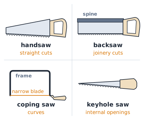
A general handsaw makes straight cuts by hand, while a backsaw has a stiffening spine that helps with controlled straight joinery cuts. A coping saw has a narrow blade held in a frame and is useful for curves and fitting profiles. A keyhole or pad saw can reach certain internal openings after a starter hole. Tooth count, sharpness, and tooth form matter along with saw type. A backsaw’s stiff spine may restrict cut depth, which is a tradeoff rather than evidence that it is a universal saw.
Coping saw versus jigsaw
A coping saw is hand powered and often used for detailed curves, while a jigsaw drives a narrow reciprocating blade electrically for curved and shaped cuts. Neither automatically produces the straightest finish on an unsupported long rip. The blade must be appropriate for thickness and material, and the work must be secure. A tight curve cannot be guaranteed simply because a saw has a narrow blade; turning radius, teeth, and workpiece thickness matter. Identify whether the exam asks about curved profiles or long straight stock cuts.
Circular saw and its common use
A handheld circular saw uses a rotating blade and commonly performs straight cuts in boards or panels using suitable guides and supports. Its blade guard and workpiece support are critical: an unsupported offcut can pinch the blade or fall unexpectedly. Blade depth, blade type, and manufacturer guidance influence safe operation. When a question asks for a portable powered tool to make a long straight cut in plywood, the circular saw may be the intended choice, not a coping saw or wood lathe. Never treat portability as permission to bypass guarding.
Table saw: fence and miter gauge
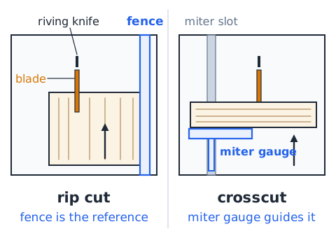
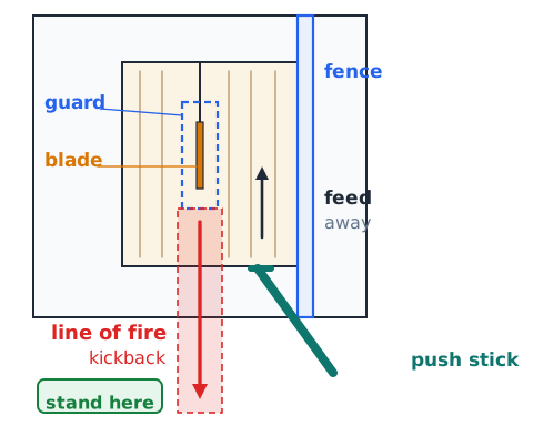
A table saw has a rotating blade projecting through a table. For common ripping operations, a properly aligned rip fence serves as the reference; a miter gauge guides many crosscuts. Using a fence and a miter gauge together carelessly can trap a cutoff and create a kickback hazard. Blade guards, a properly aligned splitter or riving knife as appropriate, anti-kickback protections, and other mandated safeguards matter. OSHA establishes guarding and spreader requirements for hand-fed ripsaws. The safety control is not optional because a task appears quick or easy.
Kickback and the line of fire
Kickback occurs when a saw or workpiece suddenly moves because of binding, pinching, or other hazardous interaction. On a table saw, stock can be propelled toward the operator. Keep the cutting path and potential ejection zone in mind, maintain functioning guards and alignment, support stock, and use proper feeding aids. A push stick or push block supplements required guarding; it is not a reason to remove guards. A question that proposes catching a thrown workpiece by hand is describing a dangerous response, not a valid recovery method.
Band saw characteristics
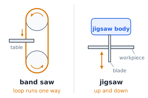
A band saw uses a continuous loop of blade around wheels and can make curved or straight cuts with appropriate blade selection and setup. Guides help stabilize the exposed working portion of the blade. OSHA’s woodworking requirements call for guarding of the blade except its working portion, fully enclosed wheels, and other controls. The band saw differs from a jigsaw because the blade moves continuously in one direction around the wheels, not up and down as a reciprocating blade. Curvature still depends on blade width and job setup.
Miter saw and bevel angle
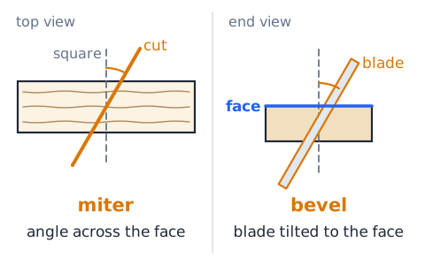
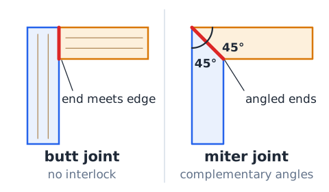
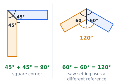
A miter saw is often selected for repeatable crosscuts and angled cuts across boards. A miter is an angle in the horizontal cutting plane relative to a square crosscut; a bevel tilts the blade relative to the face of the material. Compound miter saws can combine those settings. Always identify which angle a problem specifies before calculating a finished edge. A nominal 45-degree miter on each of two properly fitting pieces can form a 90-degree corner, but poor alignment or an incorrect reference can spoil the joint.
The drill and twist bit
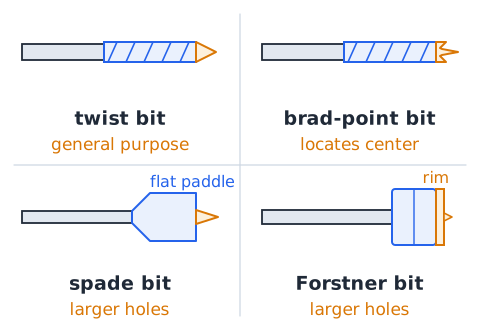
A drill rotates a bit to make a hole; a twist bit is a common general-purpose drilling bit. A wood brad-point bit helps locate the starting center, while spade bits and Forstner bits are associated with larger wood holes but have different cutting characteristics. Hole diameter is set by the bit, not the distance between lines on a tape. Secure the material, use appropriate support, choose the correct speed and bit, and follow manufacturer instructions. Removing a guard or holding small material in the palm is not a proper shortcut.
Pilot holes and countersinks
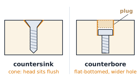
A pilot hole is a smaller hole drilled ahead of a screw, often reducing splitting and helping alignment. The appropriate diameter depends on the fastener, species, and application. A countersink creates a tapered recess that allows a matching flat-head screw to sit flush or below the surface; a counterbore produces a generally flat-bottomed, larger-diameter recess. These are different geometries. If an exam asks what prevents a screw head from standing proud when using a flat-head screw, a countersink is the relevant concept.
Clamps and controlled holding
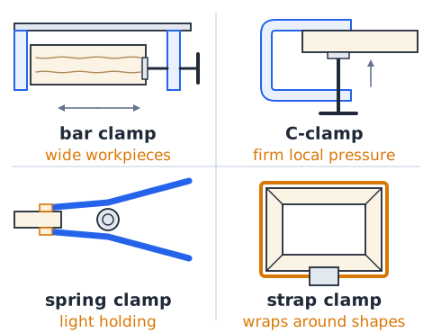
Bar clamps span relatively wide workpieces, while spring clamps apply convenient light holding force. C-clamps use a screw mechanism and can supply firm local clamping, and web or strap clamps can wrap around some shapes. Clamps hold material in position while glue cures, while a cut is laid out, or while other permitted operations take place. Excessive pressure can dent soft wood or distort an assembly. Do not use clamps in place of required guards or place your hand near a cutting zone merely because the piece is clamped.
Bench vise and bench dog
A woodworking vise secures a board against a bench or jaw; bench dogs can support and resist movement of flat stock in compatible bench holes. This is particularly useful for hand planing. Jaw pads can help protect the surface. A vise is not interchangeable with a machine-specific workholding fixture: an object secure for chiseling may not be safely secured for drilling. Determine whether the question requires positioning, alignment, restraint against feed force, or a particular clearance for the tool’s path.
Wood chisel: bevel and edge
A wood chisel has a sharpened edge for paring or chopping wood. The bevel and flat reference face help control its action, although exact technique depends on the task. A mortise chisel may be stronger for particular chopping work than a delicate paring chisel. Keep hands out of the edge’s path and secure the workpiece. Never strike a hand-held sharp edge toward your supporting hand. A chisel removes wood mechanically; it is not a substitute for a screwdriver or a pry bar.
Mallet versus hammer
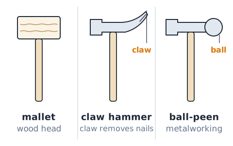
A wooden or non-marring mallet can drive suitable chisels or tap wooden assemblies without the same surface impact as a hardened steel hammer. A claw hammer is used for driving certain nails and its claw removes nails. A ball-peen hammer is primarily associated with metalworking rather than fine cabinet joinery. Not every chisel handle is designed to be struck, and the striking tool must suit the handle. Identify the material and finish requirements first: force alone does not determine tool choice.
Hand plane and the shaving
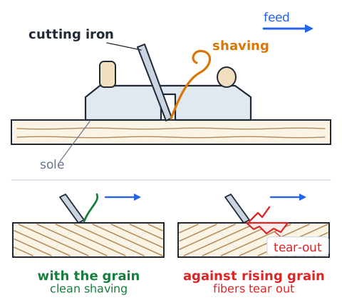
A hand plane removes thin shavings from wood using an adjustable cutting iron. Depending on its design and setup, it can flatten, smooth, or shape a surface. Grain direction matters because cutting against rising grain may tear fibers out instead of leaving a clean shaving. A jointer plane is typically longer and suited to straightening extended edges; a block plane often handles small trim tasks. The exam may contrast shaving material from a surface with sawing a board into pieces. Those are fundamentally different operations.
Power planer and thickness planer
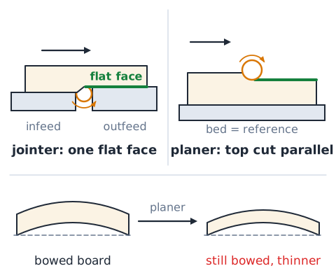
A portable power planer removes a controlled strip from a face or edge, whereas a thickness planer machines a face relative to the opposing reference face. A thickness planer does not automatically make a twisted board flat just by reducing its thickness. This is why establishing a flat reference surface can matter before final thicknessing. Cutting heads are hazards, and machine-specific guards and manufacturer instructions govern operation. Confusing a jointer with a thickness planer is a frequent reasoning trap; one establishes reference flatness, the other can produce consistent thickness relative to a reference.
Jointer: flattening one face
A jointer uses cutterhead action and tables to establish a flat face or straight edge when properly set up. The workpiece moves over the cutter; the infeed and outfeed tables establish the cutting relationship. Its job differs from a thickness planer, which references the opposite side. OSHA addresses jointer cutting-head guarding and table openings because accessible revolving knives present a severe hazard. Workpiece dimensions, stock condition, and equipment limitations determine whether the operation is appropriate. Never assume short or thin material is safe simply because the machine is familiar.
Router and the shaped profile
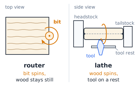
A router rotates a cutting bit to make profiles, rabbets, grooves, and other shapes with appropriate guides and fixtures. It can create a decorative edge or a controlled recess that a plain saw would not form conveniently. Feed direction and workholding are important because rotating cutters can grab material. Bits must match the router’s ratings and the task. Distinguish a router from a wood lathe: the router’s bit rotates while the workpiece normally remains stationary, whereas a lathe rotates the workpiece against a cutting tool.
Lathe and turning tools
A wood lathe rotates a secured workpiece about an axis so a properly supported cutting tool can shape a round profile. Examples include spindle shapes and some bowls, subject to correct equipment and methods. The spinning stock, tool rest, and cutting position create hazards if poorly set. Identifying a lathe is straightforward in an exam description: the wood rotates, rather than a drill bit boring into stationary wood. Spinning a square blank also changes the clearance needed around the workpiece during preparation.
Sanding: grit and scratch direction
Sandpaper uses abrasive particles to remove fine material. A lower grit number generally indicates coarser abrasive and faster scratch-producing removal, while a higher grit usually gives a finer surface. Move through an appropriate sequence instead of expecting very fine paper to erase deep damage quickly. A sanding block distributes pressure and can help prevent localized dips. Sanding is a finishing and shaping operation, not a reliable way to make a severely bowed board straight. Wood dust controls remain relevant even when the tool appears low power.
Belt sander versus orbital sander
A belt sander moves an abrasive belt and can remove material quickly; it can also create gouges if left unevenly on a surface. A random-orbit sander uses a different motion and is often chosen for general surface preparation. Tool selection is a tradeoff between removal speed, finish, access, and control. Sanding with a tool lacking effective dust extraction may expose the user to airborne wood dust. Exam distractors may imply that finer grits always remove material faster; that confuses finish quality with removal rate.
Respirable wood dust
Cutting, routing, and sanding can generate airborne dust. NIOSH documents that wood dust may irritate the eyes and skin, impair breathing, and contribute to serious health effects; some exposures are associated with cancer. Local exhaust ventilation and effective dust collection are important engineering controls, alongside appropriate work practices and protective equipment. A paper dust mask should not be assumed sufficient for every workplace hazard. The exam’s safest action usually favors a controlled process rather than merely cleaning visible chips after the job.
Sawdust, chips, and housekeeping
Large chips on a bench and fine airborne dust pose different problems. Slippery or cluttered floors increase trip hazards, while dust collecting near equipment can interfere with components or contribute to fire risks under some conditions. OSHA calls for cleanliness around woodworking machinery as part of machine maintenance. Use specified collection methods rather than blowing dust into the air with compressed air as a routine cleanup shortcut. Keep offcuts sorted and remove defective scrap before it becomes mistaken for sound stock.
Eye, hearing, and hand protection
Safety glasses or suitable face protection address flying particles; hearing protection may be needed around noisy equipment. Appropriate clothing and secured hair reduce entanglement risks. Gloves are not universally safe around rotating machinery because some can be caught; follow the equipment-specific rules. Protection has layers: engineering guards, sound work practices, suitable personal protection, and trained operation all matter. An answer that recommends removing a guard because the operator wears goggles is wrong: protective eyewear does not stop a hand from contacting a rotating blade.
Guarding and energy isolation
Guards are barriers between an operator and hazardous moving parts. When servicing a machine creates a risk of unexpected energization, the applicable energy-control procedure must isolate and secure the energy source; simply tapping the power switch is not equivalent. OSHA 29 CFR 1910.147 addresses hazardous energy in covered workplaces, and OSHA 1910.213 provides machine-specific woodworking requirements. An exam scenario that involves reaching into the blade path while power is available should trigger the need for proper shutdown and protection, not improvisation.
The blade is not the only hazard
A workpiece can become a projectile through kickback or a loose fixture, and noise, dust, splinters, and pinch points also matter. The point of operation is where the machine works on material, but risk extends beyond that point. OSHA’s general machine-guarding standard explicitly addresses rotating parts, ingoing nip points, and flying chips. A safe plan evaluates stock support and the operator’s position, not just the exposed cutting edge. Recognize why seemingly sensible actions such as pulling trapped material by hand can be hazardous.
Moisture content and movement
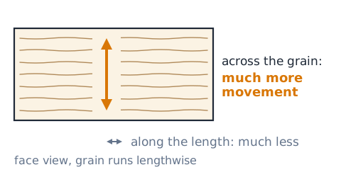
Wood absorbs and releases moisture from its surroundings. Many boards change width across the grain as moisture varies, while longitudinal movement is generally much smaller. That behavior matters when fastening a wide solid tabletop or storing lumber before joinery. Panels made from different constituents can move differently. A tight joint that prevents all movement may split with changing humidity. In a conceptual question, a board that expands or contracts after installation suggests a moisture-related explanation rather than a failure of arithmetic alone.
Warp: bow, cup, twist, crook
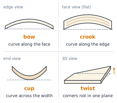
Bow describes curvature along a board’s face over its length; crook refers to edgewise curvature. Cup is curvature across a board’s width, while twist means corners do not lie in one plane. These are distinct defects and indicate different corrective actions. A straightedge along a face may reveal bow, whereas a winding-stick setup can reveal twist. Reducing thickness alone cannot be assumed to remove every defect. For exam drawings, pay attention to the direction of deformation and the reference surface shown.
Checking flat, straight, and square
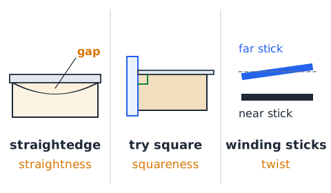
Flatness means a surface approximates a plane; straightness concerns a line or edge; squareness concerns a 90-degree relation. A long straightedge can help reveal gaps under an edge, but it does not by itself certify the right angle between adjoining faces. A try square assesses that relationship. A winding stick pair helps reveal twist across a workpiece. Choose the measuring method for the property being tested. This vocabulary can eliminate distractors that propose one tool for every geometry check.
Wood adhesive and clamp time
Woodworking adhesives bond prepared surfaces under suitable application and curing conditions. Surfaces must be appropriately fit, and the manufacturer’s specification determines open time, clamp time, and full cure. Clamping force should establish contact without starved joints or crushed material. Glue squeeze-out does not automatically prove a strong bond. Adhesive is different from nails or screws, which provide mechanical fastening. Safety measures may include ventilation or protective practices depending on the chemistry; never treat all adhesives as identical.
Butt joint and reinforcement
A butt joint joins the end or edge of one member against another without interlocking features in its simplest form. It is easy to visualize but may require proper fastening or reinforcement depending on load and grain orientation. Joining end grain alone may not provide the same glue strength as suitable long-grain bonds. A butt joint differs from a miter joint, where adjoining ends are cut at complementary angles. In exam pictures, first locate the mating surfaces, then determine whether they overlap, interlock, or only meet face-to-face.
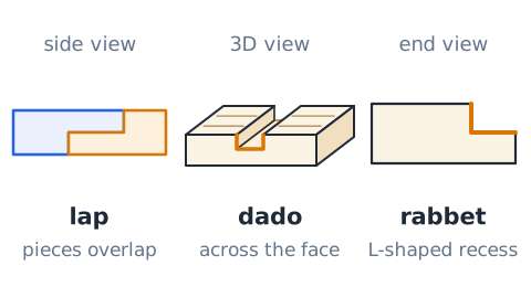
Lap, dado, and rabbet joints
A lap joint overlaps portions of two pieces, often with material removed to allow flush assembly. A dado is a groove across the grain of a board’s face that can receive a shelf; a rabbet is an L-shaped recess along an edge or end. In technical woodworking usage, a groove often runs with the grain, while a dado commonly runs across it. A single drawing can show the difference even if terminology varies by region. These joints change the bearing and locating surfaces available for a connection.
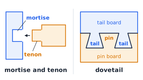
Mortise-and-tenon and dovetail
A mortise is a cavity that accepts a projecting tenon, creating a traditional frame joint. A dovetail has tapered interlocking tails and pins that resist separation in a particular direction. Neither name refers to a type of nail or screw. When distinguishing joinery in an exam sketch, imagine how the pieces slide together: a tenon enters a matching socket, while dovetail profiles interlock laterally. Joint strength depends on geometry, material, fit, and construction; naming a joint does not guarantee a given load rating.
Nails, screws, and withdrawal
Nails are often installed rapidly and can resist certain shear loads, while screws have threads that can provide substantial withdrawal resistance in appropriate materials. Actual performance depends on fastener size, penetration, pilot-hole selection, grain direction, and design. Driving a screw close to a board’s edge without a proper pilot hole can split the wood. A countersink shapes a screw-head recess; it is not a substitute for selecting adequate embedment. Exam questions frequently ask which component best matches the joining method rather than request engineering design.
Countersink, counterbore, and plug
A countersink makes a conical recess for a tapered fastener head. A counterbore produces a cylindrical, larger-diameter recess, often used when a fastener head must sit below a surface or be covered by a plug. A wood plug can conceal a recessed fastener while remaining visually similar to the material. Determine the head shape shown in the question before choosing a hole geometry. Misreading these terms makes an otherwise simple drill-bit selection problem seem more difficult than it is.
Miters and equal angles
Two matching 45-degree miters can form a 90-degree frame corner when the pieces meet properly. This is a simple angle relationship, not proof that the joint is strong enough without suitable joining design. If the intended included corner angle is 120 degrees and both symmetric miters are measured as half that included angle in the specific drawing, each mating angle is 60 degrees; the exact miter-saw setting uses a different reference and must be checked. Never assume an angle label uses the same baseline across all diagrams.
Board feet: volume rather than length
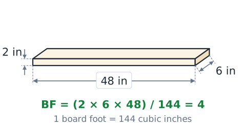
A board foot is a lumber volume corresponding to 144 cubic inches: a piece 1 inch thick, 12 inches wide, and 12 inches long. For dimensions in inches, divide thickness times width times length by 144. A 2 × 6 × 48 inch actual-dimension rectangular piece has 4 board feet by volume; if “2 × 6” is merely a nominal size, actual volume differs. This is a teaching calculation, not a substitute for a merchant’s pricing convention.
Area and plywood panels
A sheet 4 feet wide and 8 feet long has 32 square feet of one-face area. If two rectangular faces must be painted, area can double, but edges and waste may add more.
Square footage is not the same as board-foot volume; the unit should help you decide which formula to use. For floor sheathing or a panel layout problem, calculate usable material area and check the cutting constraints. Even if total area fits, a single required piece might not fit a narrow panel.
Perimeter, trim, and miter waste
Perimeter is the distance around a rectangular outline: twice length plus twice width. A cabinet frame with outside dimensions 3 by 2 feet has a geometric perimeter of 10 feet, before allowances for joints, offsets, and cutting waste. Be careful whether the question requests material length, inside perimeter, or outside perimeter; miters alter where measurements land. A frame calculation can be numerically neat and still give the wrong answer if the selected reference edge is not identified.
Fraction arithmetic for cut planning
Fractional inches occur frequently in layout questions. To add 5/8 and 3/16 inch, use denominator 16:
To subtract 1/8 from 1 1/4 inch, rewrite the mixed number as 10/8 and obtain
1/8 inches. Mark positions from one common datum where possible. Fractions describe quantities; they are not instructions to round away material. Simplifying units before arithmetic reduces exam mistakes.
Kerf calculation with multiple blanks
Suppose three 10-inch blanks will be cut sequentially from stock and each required separation cut removes 1/8 inch. Under an assumption of three complete separation cuts and no end-trimming allowance, the required length is
3/8 inches. If the final part uses the natural stock end without an additional cutoff, the count can differ. That is why you must read the cutting sequence in the question. An attractive answer of exactly 30 inches ignores the missing sawdust.
Scale drawings and simple ratios
A shop drawing may use a stated scale. At 1:4 scale, one unit on the sketch represents four of the same units on the object; a 3-inch measured line represents 12 inches in reality. A dimension printed on a drawing normally takes precedence over measuring the line unless instructed otherwise. Do not mix metric and customary units inside a scale calculation without converting first. A scale ratio is a geometric relationship and does not indicate which saw or joint should be selected.
Square, parallel, and plumb vocabulary
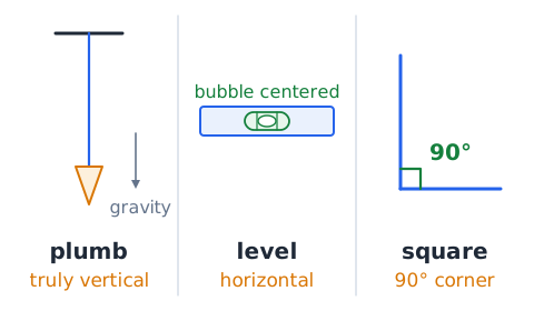
Two lines are parallel when they maintain direction without intersecting in a flat plane. Perpendicular lines meet at a right angle; square is the related workshop term. Plumb means truly vertical relative to gravity, and level means horizontal relative to gravity. A shelf may be level without its edge being square to a misaligned cabinet side. These distinctions become important in layout and assembly questions. Choose the tool based on whether the problem tests an internal 90-degree corner, horizontal installation, or matching parallel lines.
Workpiece support and clamping geometry
An accurate cut can still be unsafe when the stock is poorly supported. Long panels require suitable infeed and outfeed support; narrow parts may need purpose-designed jigs or fixtures. A piece pinched between a cutting tool and a fixed stop can move unpredictably. If a diagram shows a clamp located directly in the tool path, that layout is defective even if the final dimension is correct. Determine where force travels through the stock and how the offcut will behave when detached.
Blades: tooth count and material
Blade tooth geometry and count influence finish, feed behavior, and suitability for different materials. A finer-tooth blade is often selected for a cleaner cut in some applications, but no single count universally works for all woods and machines. Blade diameter, arbor fit, maximum speed, and manufacturer recommendations are mandatory selection constraints. Do not mount a blade merely because its outside diameter looks close enough. A dull or damaged blade should be removed from service rather than forced through the work.
Tool inspections before work
Inspect handles, guards, cords, blades, and bits before use. A cracked handle can fail; a bent blade or damaged guard can compromise control. Verify the machine is properly adjusted for the task, the workpiece is supported, and the selected tool is rated for its intended operation. OSHA’s woodworking machinery rules call for removing dull, improperly set, or improperly tensioned saws from service. Proper inspection is a preventive task, not something postponed until the cut feels difficult.
Stopping and troubleshooting a bad cut
Burn marks, excessive vibration, bogging, irregular surfaces, and unexpected grabbing are warning signs to stop and reassess the setup. The cause may involve blade condition, feed rate, alignment, material binding, or an unsuitable operation. Do not diagnose every symptom as a dull blade without checking the other variables. Corrective work must respect the equipment’s shutdown and energy-control requirements. The ASVAB often rewards identification of the most plausible safe next step rather than blind adjustment during machine motion.
When a hand tool is the better answer
For a small controlled recess, a sharp chisel may be a better fit than a large power saw; for extensive panel cuts a properly equipped power saw may be more practical than a coping saw. A handsaw can be suited to a one-off job without electrical power. Consider cut type, required finish, work size, access, and safety controls. More motor power does not automatically mean greater precision. Tools have overlapping capabilities, but their primary intended operation gives the strongest clue in typical Shop Information questions.
Worked example: identify the cut
A board is 48 inches long, and a student needs to split its width into two long strips. Since the cut runs along the long fibers, the operation is a rip cut. If instead the student shortens the board from 48 to 36 inches by cutting across its width, that is a crosscut. The workpiece can be the same in both descriptions. The decisive evidence is the direction of the cut relative to the grain, not whether a large or small saw is named in the choices.
Worked example: select a recess
A drawing shows a flat-head wood screw that must finish flush with the top face. A taper-shaped countersink is the relevant recess because it matches the underside of the typical flat head. If the drawing shows a socket-head screw sitting below the surface in a cylindrical cavity, counterboring may instead be appropriate. This problem tests a match between tool geometry and desired shape. It does not ask whether more torque makes the head disappear; overtightening can damage the joint.
Worked example: minimize a panel cut error
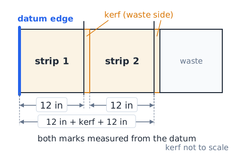
A panel must have two strips measuring 12 inches from the same straight edge. If the first strip is cut with a wide kerf, measuring the second strip from the already shortened remainder without accounting for that cut can shift the layout. A better plan identifies the datum, measurements, actual blade kerf, and waste side of each mark before sawing. In an exam calculation with a specified kerf, explicitly subtract material removed. In a real shop, also confirm dimensions with a measured test cut as permitted.
Worked example: recognize sanding quality
After rough shaping, a worker wants to remove shallow scratches before applying finish. A sanding block with appropriate abrasive and grain-aware strokes is more relevant than a nail set or tap wrench. If deep planing ridges remain, starting at an extremely fine grit will be inefficient. Choose a sensible grit progression and keep the surface supported. A dust extraction setup does not replace the need for a suitably chosen abrasive, and a fine abrasive does not eliminate airborne dust exposure.
Exam strategy: classify before comparing
Translate the prompt into an operation word: rip, crosscut, bore, plane, clamp, sand, join, or layout. Then eliminate choices that cannot perform that basic operation. For tool drawings, identify moving parts: a continuous band blade, a reciprocating narrow blade, a rotating drill bit, or a rotating workpiece are diagnostic clues. For dimensions, note every unit and whether the question asks for area, length, or volume. Never choose an unsafe answer merely because it looks fastest; the official test is about shop knowledge, not risky shortcuts.
Common trap: rip and crosscut reversed
A distractor may say a crosscut saw is chosen whenever the cut happens at the end of a board. That wording ignores grain direction. A crosscut severs fibers transversely; a rip follows the lengthwise fibers. Some machines can use suitable blades for either job, but the fundamental terms remain distinct. Ask yourself which fibers the cutting edge encounters rather than relying on the apparent orientation of a photograph. On plywood, take account of its layered grain and blade recommendations instead of forcing the solid-wood rule literally.
Common trap: flattening versus thicknessing
A jointer is commonly used to create a flat reference face or straight edge. A thickness planer produces a face related to the opposite reference surface. Passing an already twisted board through a thickness planer does not inherently remove twist, because the stock may flatten temporarily as it feeds. The distractor often names both machines as if they perform identical reference operations. Identify whether the problem needs one true face or a consistent thickness; the machines may be used in sequence, but they are not interchangeable.
Common trap: dimensions and kerf
A four-part cut list adding to the full stock length is not necessarily feasible: saw cuts remove material. Similarly, a board labeled with nominal dimensions may have a different actual cross-section. Read stated dimensions, note whether stock is planed, count required cuts, and convert mixed numbers without decimal shortcuts. A right numeric answer with the wrong unit is still incorrect. Keep inch, square inch, and board foot separate because they measure length, area, and volume respectively.
Guided recall: shop vocabulary
Say the correct operation for each description before looking at choices: lengthwise grain separation is a rip cut; short cross-grain separation is a crosscut; a tapered recess for a flat-head screw is a countersink; removing thin shavings with an iron is planing; holding parts under controlled pressure uses a clamp. Then contrast adjoining concepts: rabbets occur at edges, dados run across faces, and a mortise accepts a tenon. For safety, recall guards, stock support, dust control, and energy isolation when maintenance exposes dangerous moving parts.
Final shop decision checklist
First name the material and its grain direction. Second choose the intended operation, not merely a familiar tool. Third identify reference surfaces, dimensions, and any removed kerf. Fourth match the machine or hand tool to the job and inspect its condition. Fifth confirm guarding, supports, workholding, dust controls, and appropriate protective practices before any real operation. Finally, verify that the resulting joint, cut, or surface matches the drawing. This checklist supports ASVAB recognition questions but does not replace supervised equipment training or workplace procedures.
 English ▾