 ASVAB Camp
What this metalworking lesson tests
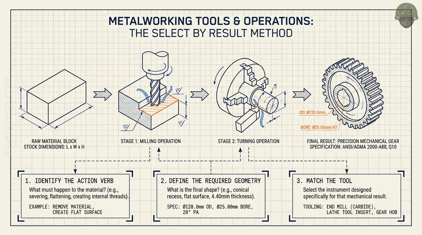
Shop Information on the ASVAB focuses on identifying tools, understanding shop language, and matching an operation to its purpose. Metalworking questions may show a tool, name a desired shape, or ask which machine produces a particular feature. You need not operate a lathe to recognize that it turns a workpiece while a cutting tool advances. This lesson explains cutting, forming, measuring, threading, deburring, and shop hazards. It is educational examination preparation, not authorization to use industrial machinery without training.
Metalworking versus assembly
Metalworking changes stock size, shape, finish, or properties. Assembly joins pieces that may already be shaped. Sawing and shearing separate material; drilling makes round holes; milling produces surfaces and slots; turning usually generates cylindrical features; bending reshapes a part without deliberately cutting it. Many real jobs combine these steps. Exam problems become easier when you first classify what must happen to the material, then select the appropriate tool rather than memorizing a disconnected list.
Common forms of metal stock
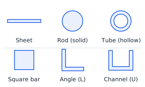
Metal is supplied as sheet, plate, bar, rod, tube, angle, channel, and other profiles. Sheet is relatively thin flat stock, while bars may have circular, rectangular, or square cross sections. A tube has a hollow interior; a solid rod does not. Angle stock has an L-shaped cross section and channel stock resembles a U. Shop drawings show the required final part, so do not infer that every round-looking part began as round bar.
Ferrous and nonferrous metals
Ferrous metals contain iron as a principal component; common carbon steels are examples. Nonferrous categories include aluminum, copper, brass, and bronze. A magnet can be useful for some identification tasks, but not all iron-containing alloys are strongly magnetic and magnets do not determine composition or grade. Metal selection depends on strength, corrosion resistance, machinability, weight, and the intended environment. An ASVAB question may ask you to distinguish a metal from its shape or process rather than name a specific alloy.
Ductility, malleability, and brittleness
Ductility describes a material’s ability to undergo significant tensile deformation before fracture; malleability describes plastic deformation under compression, such as rolling into sheet. Brittleness refers to fracture with comparatively little plastic deformation. These are not synonyms for hardness. A hard material may be brittle, but hardness alone does not determine whether it can be bent safely. Recognize the force direction and the intended change of shape before choosing between drawing, rolling, and fracture-related descriptions.
Hardness versus strength
Hardness generally reflects resistance to localized indentation or scratching, while strength refers to resistance to specified loads or failure modes. A file cuts when its teeth are suitable for the workpiece; the relative hardness of tool and work matters. Heat treatment may change a steel’s hardness and toughness but not always in the same direction. Avoid distractors claiming that harder always means tougher or that all metals have the same response to heating.
Workholding before tool selection
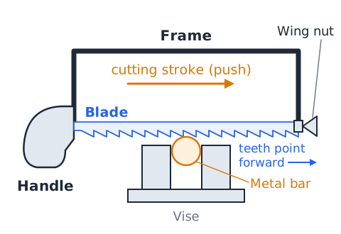
A workpiece must be supported and constrained for the intended process. A bench vise commonly secures small stationary work for hand filing or hacksawing; clamps and fixtures locate work for machines. Machine workholding is not interchangeable with holding stock in a bare hand. The correct arrangement depends on the equipment and instructions. Look for cues such as 'secure a metal strip for hand filing' or 'hold a round workpiece during turning' and choose a matching holding device.
Bench vise versus machine vise
A bench vise is mounted at a workbench and holds material for manual operations. A machine vise secures stock on equipment such as a milling machine or drill press when suitable for that setup. A lathe chuck grips a workpiece for rotational operations. A chuck key is removed before operation; leaving it installed is an obvious hazard. A question that confuses these workholding methods usually tests whether the part or the tool rotates.
Hacksaw function
A hacksaw is a hand tool designed to cut materials using a replaceable, toothed blade held in a frame. Blade tooth pitch is selected to suit stock thickness and material, with several teeth engaged where appropriate to limit snagging. It is not intended to flatten surfaces like a file or create internal threads like a tap. Use the question’s verb: severing a small metal bar points toward a saw, while refining a cut edge points toward a finishing tool.
Hacksaw blade tooth pitch
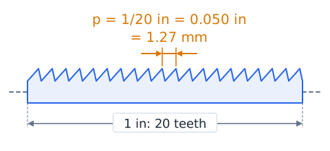
Teeth per inch (TPI) indicates how closely blade teeth are spaced. A higher TPI has smaller, more closely spaced teeth and is often useful for thinner stock, while coarser pitches may suit thicker material, subject to manufacturer guidance. TPI is a count per unit of blade length, not a cutting speed. If 24 teeth occupy one inch of blade, the approximate tooth spacing is one twenty-fourth of an inch. Do not confuse hacksaw blade TPI with screw-thread TPI.
Tooth-spacing example
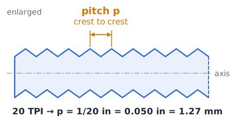
Suppose a blade has 20 evenly spaced teeth per inch. A simplified average spacing is one inch divided by 20, or 0.050 inch. Multiplying by exactly 25.4 millimeters per inch gives 1.27 millimeters. Real tooth sets and profiles differ, so this is a pitch interpretation rather than a blade-selection rule. On ASVAB-style arithmetic, state the unit and distinguish a count of teeth from distance between them.
Files remove small amounts of metal
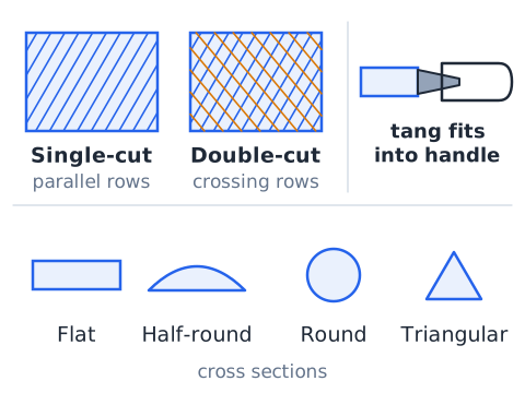
A hand file is a hardened, toothed tool used to remove material, deburr edges, and bring a surface toward a desired shape. Flat, half-round, round, and triangular file shapes serve different contours. A file is not a wrench and should not be used as a pry bar. File teeth and technique must match the work and guidance. For identification questions, the fact that a file removes thin chips is more important than memorizing a precise stroke rate.
File cuts and surface finish
Coarse files remove material more aggressively while finer tooth arrangements generally aid control and finishing. A bastard-cut file is a familiar broad-grade term, not a statement that it is defective. Single-cut files have rows of roughly parallel teeth; double-cut files have crossing sets of teeth for different cutting characteristics. A smooth finish may require a further abrasive step. Neither a fine file nor a grinding wheel is appropriate for every material without checking the manufacturer’s guidance.
File handles and tang safety
The pointed tang of a conventional hand file is designed to fit an appropriate handle, not serve as a handle itself. An exposed tang creates an injury risk if force causes the hand to slip. Inspect file teeth and the fitted handle before use, and do not use a cracked, loose, or damaged handle. OSHA’s hand-tool standards establish a general rule against unsafe defective tools; they do not provide a universal filing procedure for every material.
Draw filing and cross filing
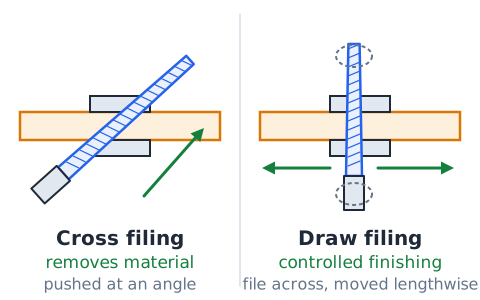
In cross filing, the file commonly travels at an angle across a surface to remove material. Draw filing is a controlled finishing technique in which the file is held across the work and moved lengthwise. The exam emphasis is recognizing that filing removes thin layers to refine an edge or face. Do not treat filing as a substitute for machining a precise hole; selecting a process begins with the required final geometry and tolerance.
Deburring after separation
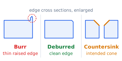
Sawing, drilling, shearing, and milling can leave burrs: thin raised edges or protrusions formed at a cut. A deburring tool, file, or appropriate abrasive may remove them. Burrs can interfere with safe handling, seating, or measurement. The result of deburring is an improved edge, not necessarily a fully polished surface. Distinguish removing a sharp burr from making a countersink; the latter intentionally creates a conical recess at a hole.
Center punch and layout marks
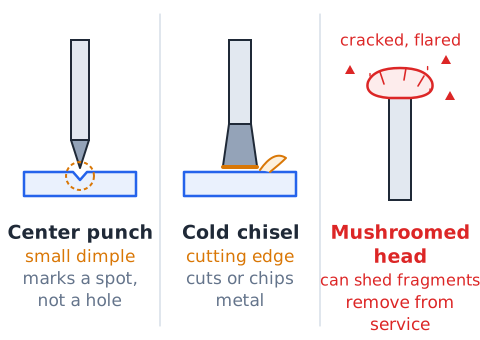
A center punch creates a small indentation marking a location, commonly assisting the start of a drilled hole when appropriate for the material and process. A prick punch is typically associated with finer layout marks. The indentation is a position mark, not a complete drilled hole. A question asking which tool makes a small starting dimple usually points to the punch, while measuring its location calls for a rule, square, or caliper.
Cold chisel versus punch
A cold chisel is a hand cutting tool used with proper support and striking technique to cut or chip certain metals without heating the work to forging temperature. A punch makes or transfers marks and can serve various pin-related tasks depending on type. Neither tool should be mistaken for a tap, which creates an internal thread. Struck heads and handles require inspection; a mushroomed head can shed fragments and should not continue in unsafe service.
Snips and sheet-metal shears
Hand snips are tools for cutting appropriate sheet-metal stock. Straight-cut, left-cut, and right-cut styles are chosen for cut geometry and stock suitability, not because every left-handed worker must select a left-cut tool. Shears also separate sheet by blades acting across the material. Neither snips nor shears are intended to make round internal threads. Exam scenarios often contrast separating thin sheet with drilling holes through thick blocks.
Bench shears and power shears
A bench or power shear cuts sheet or plate within the machine’s rated capacity and configuration. A shear can create edges with burrs or distortion that require secondary work. Capacity is not a generic property shared by all shears. With powered machinery, point-of-operation guarding and safe material handling are essential; OSHA 1910.212 addresses general guarding requirements. For test identification, the core action is a linear cut through sheet material.
Cutoff saws versus grinding wheels
A metal-cutting saw or cutoff machine is selected for separating material, while a grinding wheel is an abrasive tool for removing material or finishing, depending on its design. Never assume any grinding wheel may be used for side pressure or cutting. Abrasive-wheel selection, mounting, guards, and rated speed follow the wheel and machine instructions. In an exam question, 'finish a rough edge' and 'separate a bar into two pieces' signal different purposes even if both machines can remove metal.
Bench grinder: what it does
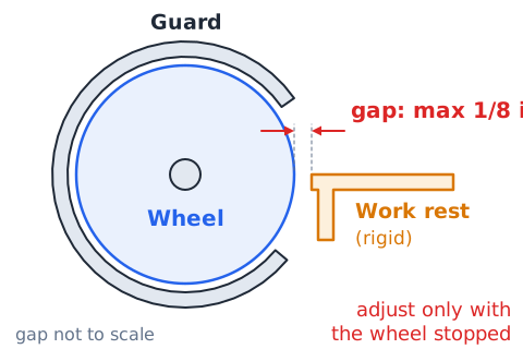
A bench grinder generally uses an abrasive wheel to remove material, reshape small components, or assist sharpening when the wheel is appropriate. It is not a precision milling machine and does not create screw threads. OSHA 1910.215 includes work-rest and guarding requirements for applicable abrasive-wheel machinery. Real use requires training, inspection, appropriate eye/face protection, wheel compatibility, and machine-specific procedures. Do not memorize one universal grinding clearance for every equipment type.
Grinding work-rest clearance
For offhand grinding machinery covered by OSHA 1910.215(a)(4), the rigid work rest must be kept closely adjusted with a maximum opening of one-eighth inch. This helps prevent a workpiece from being pulled between the rest and wheel. The adjustment must not be made while the wheel is in motion. The 1/8-inch number is a specific rule for that stated context, not a universal gap that applies to every rotating machine or all guards.
Converting the work-rest limit
The one-eighth-inch maximum work-rest opening equals 0.125 inch. The exact length conversion is 1 inch = 25.4 mm, therefore
A classroom question may ask which equivalent is closest. The safe configuration still depends on the applicable machine and standard. Conversion alone does not verify that a particular grinder is ready to operate.
Drill press: relative motion
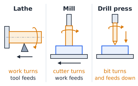
A drill press commonly rotates the drill bit and feeds it axially into a stationary, properly secured workpiece. A lathe often rotates the workpiece instead. This contrast is a common tool-identification clue. A twist drill produces a generally round hole, and a different operation may refine its diameter or finish. Chips can be sharp and hot; do not reach toward rotating tools to clear chips. Follow lockout and servicing rules when maintenance is required.
Twist-drill anatomy
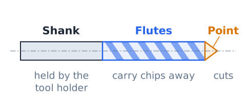
A twist drill typically has a shank that is held by the tool holder, flutes that help form cutting edges and carry chips, and a point at the cutting end. The helical flutes do not mean the drill is a threaded fastener. Larger twist drills, step drills, and specialty drills serve different tasks. On an ASVAB question, a spiral-fluted cutting tool most often indicates drilling rather than filing or tightening a bolt.
Pilot holes and final holes
A pilot hole is a smaller preparatory hole in an operation that calls for one; it can guide later drilling or prepare for other processes. It is not automatically necessary for every hole size, material, or machine. A final drilled hole may have dimensional or finish limits that require reaming, boring, or other finishing. The sequence is driven by the part specification. Distinguish a pilot hole from a tapped hole: tapping cuts or forms internal screw threads.
Countersinking versus counterboring
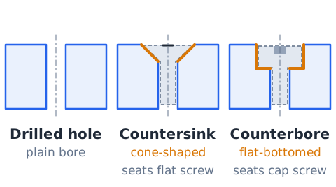
Countersinking forms a conical recess at a hole opening, commonly intended to seat a conical screw head when the design calls for it. Counterboring forms a larger cylindrical, flat-bottomed recess for a suitable fastener head or assembly feature. The two operations do not create identical shapes. Study the head shape described in the question: conical suggests countersink; cylindrical with a flat seating surface suggests counterbore. Neither is the same as cutting a screw thread.
Reaming and boring
Reaming is a hole-finishing process that removes a relatively small amount of material to improve an existing hole’s size and finish when properly applied. Boring enlarges or refines an existing hole using a cutting tool, often on a lathe or boring setup. Drilling initially creates many holes, while tapping creates internal threads. Because tool choice depends on tolerances, a simple 'makes a hole' answer may be too vague for a more advanced question.
Lathe: the workpiece rotates
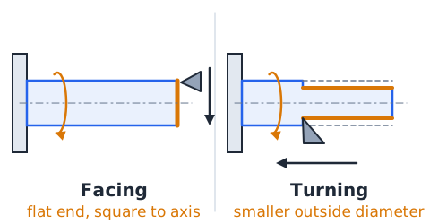
A lathe primarily rotates the workpiece while an appropriate cutting tool removes material. Common operations include turning an outside diameter, facing an end, and making certain grooves or threads using appropriate tooling. A chuck or another suitable arrangement supports the workpiece. Loose clothing and entanglement hazards make guarding and machine-specific training essential. A lathe is not defined by a rotating drill bit; that feature better describes many drill-press setups.
Facing versus straight turning
Facing machines a generally flat end surface perpendicular to the workpiece’s rotational axis; straight turning changes an outside cylindrical diameter along a length. If a cylindrical bar must become narrower uniformly along its outside surface, turning is the operation to recognize. If its end needs to become flat and square, facing is more specific. A question may mention a rotating bar but not identify the desired surface; read which face is being modified.
Milling: rotating cutter removes stock
On a milling machine, a rotating cutter removes material from a properly secured workpiece. Milling can produce slots, shoulders, pockets, and flat surfaces. In a common lathe setup, the workpiece rotates instead. End mills and face mills are specialized cutters; the mere word 'mill' does not refer to a grinding stone. Machine guarding, workholding, and training are important because rotating cutters can catch loose objects or eject chips.
Slotting and keyways
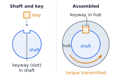
A slot is an elongated recess. A keyway is a groove intended to receive a key used in transmitting torque or locating components in some shaft-and-hub assemblies. Milling may produce many keyways when suitable. A saw kerf is not automatically a dimensionally controlled keyway. When a question describes a narrow precise groove in a metal block, milling is a stronger match than a hand snip or center punch.
Shaper versus planer principles
Traditional shaping machines use a reciprocating cutting motion to create surfaces, while planers and shapers differ in how cutter and workpiece are moved. They are less common in introductory examples than lathes or mills. The broader principle is that relative tool–work motion removes chips to form a specified surface. A distractor may claim that a shaper melts metal to form its shape; conventional machining is instead mechanical material removal.
Taps make internal threads
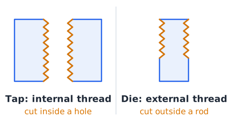
A tap produces an internal thread in a prepared hole when matched to the thread specification and process. It is not a drill bit and usually does not serve as the primary tool to make the initial hole. Tap sizes and thread forms must agree with the intended fastener. Treat a numbered or metric tap designation as a specification rather than an instruction to use maximum force. Real threading involves alignment, suitable cutting conditions, and breakage precautions.
Dies make external threads
A threading die is used to create external threads on a suitable rod or shaft. The complementary tool for internal threads is a tap. External and internal threads must have matching major properties such as diameter, pitch, form, and fit to engage correctly. A die does not bore a blind hole, and a tap does not cut the outside of a bolt. Match 'inside a hole' with tap and 'outside a rod' with die in exam choices.
Thread pitch and TPI
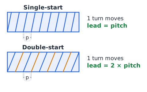
Metric screw threads commonly state pitch as an axial distance between adjacent thread crests, such as 1.5 mm. Inch-series threads may be described by threads per inch (TPI), the reciprocal of axial pitch in inches for a single-start thread. The difference is units and notation, not a contradiction. If a thread has 20 TPI, a simplified pitch is 1/20 inch = 0.050 inch = 1.27 mm. Thread fit requires more than pitch alone.
Metric thread lead in simple questions
For a standard single-start screw thread, lead (axial travel per full turn) equals pitch. If the pitch is 1.25 mm, five turns correspond to 6.25 mm of nominal axial movement, ignoring clearance and elastic effects. A multiple-start thread has a larger lead than pitch. This distinction matters when the question asks about movement, not just how many crests appear within a length. Do not transfer the lead-equals-pitch rule to a multi-start thread.
Cutting, forming, and joining compared
Machining and sawing usually remove material; bending, rolling, and stamping can plastically reshape stock; welding and brazing join components through different mechanisms. A shearing punch can separate a slug from sheet, while a marking punch only leaves a dimple. The same word 'punch' can describe a tool or part of a machine, so read context. Exam questions often provide the resulting geometry as the best clue.
Bending and the bend line
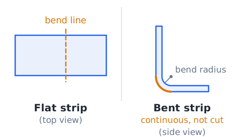
Sheet-metal bending changes the angle between portions of a workpiece using appropriate tooling. Bend radius, material grade, thickness, direction, and springback influence the result. A bend is not a cut: the material usually remains continuous through the bend region. At an introductory level, distinguish a brake used for bending sheet metal from a vehicle brake used for decelerating wheels. Complex flat-pattern calculations require additional material and process information.
Springback explained
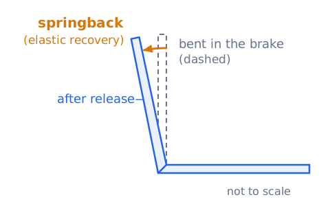
After a metal has been plastically bent, elastic recovery may cause it to relax toward its former shape. That effect is called springback. The amount depends on material and geometry; it is not always the same percentage for all metals. A shop drawing and process plan account for it. A multiple-choice distractor claiming that bending permanently removes the metal’s elasticity is too absolute. Distinguish springback from fracture and from thermal expansion.
Rivets, soldering, brazing, welding
Riveting joins parts using a mechanically deformed fastener. Soldering uses a filler metal with a lower melting temperature than brazing in commonly used technical definitions; neither is identical to fusion welding of base materials. Welding often creates a joint by coalescence with suitable heat, pressure, or both. These are broad classifications, not process instructions. Workplace requirements for welding, cutting, and brazing include fire prevention and exposure controls under OSHA 1910.252.
Welding versus oxy-fuel cutting
Welding is used to join material, while oxy-fuel cutting on suitable metals separates material through a controlled thermal/oxidation process. Not all alloys respond equally to oxy-fuel cutting, and the process is not interchangeable with plasma cutting. A tool-selection question describing a seam joining two pieces points toward welding rather than cutting. Actual hot work requires fire precautions, appropriate protection, ventilation assessment, and trained personnel.
Cast versus forged parts
Casting involves pouring or otherwise placing molten metal into a mold to solidify into shape. Forging shapes metal through compressive force, usually with suitable tooling and often at elevated temperature. A cast part is not necessarily stronger or weaker than all forged parts; material, defects, heat treatment, and geometry matter. For an exam-level distinction, 'solidifies in a mold' identifies casting, while 'deformed by dies or hammer-like force' identifies forging.
Tolerance and nominal dimensions
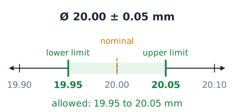
A nominal dimension is the specified reference size; a tolerance states permitted variation. A shaft specified as 20.00 ±0.05 mm has an allowed interval of 19.95 to 20.05 mm. The fact that a measurement has more printed decimal digits does not automatically make the machine more accurate. A precise operation is selected from both part geometry and acceptable tolerance. Do not classify parts as acceptable based only on being 'close' without checking limits.
Tolerance interval calculation
For a target thickness of 4.50 mm with a bilateral tolerance of ±0.10 mm, subtract 0.10 to obtain 4.40 mm and add 0.10 to obtain 4.60 mm. A measured thickness of 4.62 mm is outside that interval. This arithmetic is deterministic; real acceptance also depends on the specified measurement method and temperature. A common ASVAB-style error is adding the tolerance to both ends rather than calculating one lower and one upper limit.
Calipers versus micrometers
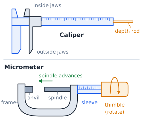
Calipers measure outside, inside, or depth dimensions within their design; micrometers are commonly selected for more specialized, often higher-resolution dimensional measurements. A measurement instrument does not become accurate solely because it displays many digits. Use the design, capacity, calibration condition, and part specification when choosing the instrument. A machinist’s rule serves faster layout measurements, but should not replace a micrometer when a question specifically requires fine dimensional discrimination.
Micrometer screw concept
A mechanical micrometer uses a precisely formed screw to convert rotation into small axial displacement. The exact divisions vary by instrument. In a simplified model, a screw advance of 0.5 mm per revolution produces 0.25 mm movement during half a turn. The thread-pitch principle is the same idea tested in fasteners, applied to measurement. Do not assume every micrometer advances 0.5 mm per turn unless the question or tool specification states so.
Dial indicators and runout
A dial indicator can detect small movement or variations in position, such as checking runout or alignment in appropriate setups. The indicator does not independently tell the cause of a deviation. Runout measurements depend on how the part is supported and referenced. An exam question may contrast an indicator used for comparative displacement with a protractor used to measure an angle. Read whether the goal is to observe small variation or record an absolute diameter.
Layout dye, scriber, and surface plate
Layout dye creates a contrasting surface that makes scribed marks easier to see. A scriber produces a fine line on a suitable surface, and a surface plate can provide a precise reference plane. A combination square may mark or check right angles. These tools locate features before machining; they do not remove enough material to create the intended final slot or bore. Do not confuse a layout line with a physical cut.
Cutting speed versus spindle speed
Cutting speed describes the linear speed at a cutting edge relative to the surface; spindle speed is the number of revolutions per unit time. For a rotating circular workpiece, surface speed increases with both diameter and RPM. A larger diameter reaches a higher surface speed at the same RPM. Actual tool speed recommendations depend on material, tool, machine, and setup and are not established by one classroom formula alone.
Surface-speed comparison
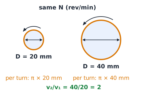
If two rotating workpieces have diameters of 20 mm and 40 mm at the same revolutions per minute, the larger has twice the circumferential distance per turn and therefore twice the surface speed. In a simplified model, v = πDN when D is the diameter and N is revolutions per unit time, with units handled consistently. This describes a geometric relationship rather than a safe or recommended cutting-speed setting.
The kerf and stock allowance
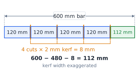
A saw cut removes a strip of material called kerf. If a layout requires multiple pieces from one bar, total stock length must allow for workpiece lengths plus the number of actual cuts and their kerf widths. Do not assume that producing n pieces always requires n cuts; the count depends on how the stock is divided and whether an offcut remains. In exam mathematics, rely on the explicitly described cuts.
Stock-cutting arithmetic
A 600 mm bar yields four 120 mm pieces after four cuts, each removing 2 mm of stock. Total piece length is
and cutting loss is
The remaining length is
This example assumes the four cuts and 2 mm kerf stated in the problem; different cutting arrangements can change the number of cuts and amount of scrap.
Coolant, lubricant, and chips
Cutting fluids may help with heat, friction, chip control, or tool life when appropriate for the material and equipment. They are not universally required and certain processes use dry cutting. Lubrication and cooling are related but distinct functions. A chip is removed workpiece material; a burr is a residual raised edge. Metalworking fluids and chips present handling and exposure issues that a beginner should recognize without treating one generic fluid as safe for all machinery.
Hazard: rotating parts and loose clothing
Rotating shafts, chucks, cutters, and workpieces can pull in gloves, loose sleeves, hair, or jewelry. Depending on the task and hazard assessment, gloves may be inappropriate near accessible rotating parts even though cut-resistant gloves may be useful for stationary sharp stock. Training and equipment instructions control the work. Machine guarding is intended to protect against rotating parts, point-of-operation hazards, and flying chips; a pair of safety glasses does not replace a machine guard.
Hazard: chips and eye protection
Sharp chips can cut skin, and metal particles can become airborne during drilling, grinding, or cutting. Eye and face protection is selected according to the hazard; OSHA guarding requirements remain relevant regardless of PPE. Reaching into an operating machine to brush chips away is unsafe. Metal chips should be managed through the appropriate stopped-equipment procedure and a tool intended for clearing them. A distractor that recommends bare-handed chip removal is not a safe choice.
Lockout and maintenance boundaries
Cleaning, adjustment, and servicing may introduce unexpected machine-startup or stored-energy hazards. OSHA 1910.147 addresses hazardous-energy control for covered servicing and maintenance. The exact steps and exceptions require employer procedures and equipment-specific knowledge. For a conceptual question, the correct principle is to prevent unplanned motion or energization, not to assume that pressing a normal stop button alone always makes maintenance safe.
Hot work: fire and fume hazards
Welding and thermal cutting may introduce ignition sources and hazardous fumes. OSHA 1910.252 outlines fire prevention and ventilation or exposure provisions; requirements depend on circumstances, materials, and process. Mechanical cutting avoids some thermal hazards but still presents chips, sharp edges, moving components, and noise. Exam preparation should recognize the broad risk difference without giving a false universal instruction such as 'every weld is safe if outdoors'.
Shop inspection checklist
Before selecting or working with a tool, identify the intended operation, material, workholding, tool condition, machine protection, and dimensional requirement. A worn or damaged tool should not be treated as acceptable merely because it still appears to work. Consider burrs after drilling, tolerance after machining, and safe disposal of metal waste. This sequence also helps exam reasoning: first ask what result is needed, then eliminate choices whose tools perform a different type of operation.
Five frequent ASVAB tool confusions
A tap cuts an internal thread, not an external thread; a die cuts an external thread. A drill makes an initial round hole, whereas a reamer finishes an existing hole. A center punch marks a location rather than making the full hole. A lathe most often rotates the workpiece, while a common mill rotates its cutter. Finally, filing removes a thin surface layer, while snips/shears separate thin sheet. These contrasts explain why similar-looking choices lead to different outcomes.
Reasoning from the operation verb
Translate each question into a verb–object pair: 'flatten the end of a rotating bar,' 'make a conical screw recess,' 'mark the center of a hole,' or 'separate thin sheet.' Match that to facing, countersinking, center punching, or shearing. Next eliminate operations that create the wrong geometry. Use units to recognize whether a problem asks for pitch, length, rotation, or tolerance. This method is more reliable than selecting the most familiar tool name.
Distinguishing exam knowledge from workplace training
Shop Information evaluates recognition and conceptual understanding; it is not a license to operate machine tools. Training, guarding, documented procedures, and manufacturer instructions are required for real equipment use. A multiple-choice question can simplify equipment roles, but actual operations may require fixtures, speeds, tooling, cooling, and process planning beyond what the prompt states. Learn the basic function, then avoid overextending the conclusion to every machine or material.
Guided concept check
Try these rapid identifications before the full test: an internal thread calls for a tap; an external thread calls for a die; a small locating indentation calls for a center punch; flattening a rotating bar end describes facing; a cylinder recess for a socket-head fastener describes counterboring; deburring removes a raised edge. If the task instead requires cutting a long slot, think about suitable milling operations. Explain why the distractor changes the wrong feature.
Final review: select by result
Remember the complete chain: layout marks position; a vise or fixture holds stock; a saw or shear separates; a drill creates a hole; a reamer finishes an existing hole; a tap and die create internal and external threads; a lathe turns a workpiece; a mill uses a rotating cutter; a file and grinder refine material. Tolerances specify acceptable limits, while PPE, guards and lockout address distinct safety hazards. Review common terminology and units before taking the 40-question lesson test.
 English ▾