 ASVAB Camp
What a fastener does
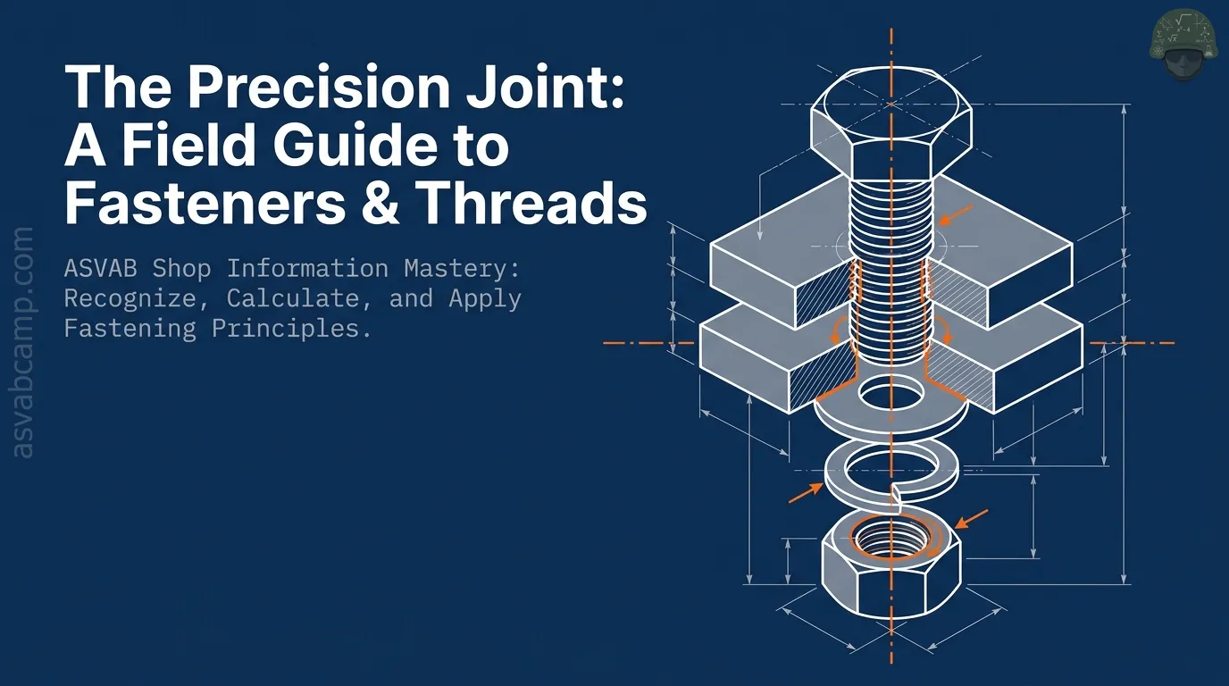
A fastener is a device used to join two or more components or retain one component in position. Threaded fasteners usually provide a removable joint; rivets and certain pins may be installed as less readily removable joints. Identify the load path before selecting a part: two plates may need resistance to sliding, opening, vibration, or a combination. The fastener is not necessarily designed to bear all external force directly because a properly clamped joint can transmit some forces by friction. For the ASVAB Shop Information subtest, first distinguish the job a fastener performs from the tool used to install it.
Bolts, screws, studs, and nuts
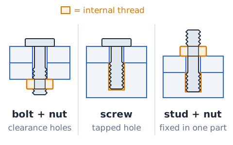
A bolt generally passes through clearance holes and is often tightened with a nut; a screw typically engages threads in a component or creates its own thread. Real engineering terminology has exceptions, so assembly configuration matters more than an oversimplified rule. A stud has external threads at both ends or along its length and may remain fixed in one part while a nut is installed on the exposed end. A nut is an internally threaded fastener. In a drawing, identify which piece has internal threads and whether the connection must be frequently disassembled.
Bolt head, shank, and threaded portion
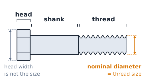
A conventional bolt has a head that receives tool force, an unthreaded or partly threaded shank, and an external thread. The shank may provide a bearing surface in a shear joint, while the threaded portion engages a nut or tapped hole. Head style influences tool access and bearing area, but the nominal diameter refers to the thread rather than the head width. A long bolt is not automatically stronger; correct grip length, thread engagement, material, and joint geometry matter. Learn these terms as labeled components rather than as isolated vocabulary.
Why thread helixes hold
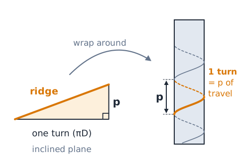
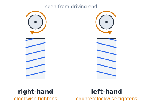
A thread wraps an inclined ridge around a cylinder. Rotating a screw converts rotation into axial travel when the mating thread is engaged. The screw does not become a magic wedge: friction, thread geometry, elastic deformation, and contact under load govern performance. In most ordinary right-hand threads, clockwise rotation viewed from the driving end tightens when the mating part is fixed, but orientation and mechanism matter. Never apply this rule blindly to specially designed left-hand or moving assemblies. In a simple Shop Information item, look for external versus internal threads and rotation direction.
Major, minor, and pitch diameters
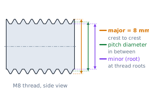
The major diameter of a typical external thread is its largest crest-to-crest diameter; the minor diameter is near the root of the thread. Pitch diameter is an intermediate effective diameter used in thread fit and inspection. A nominal M8 screw names an 8 mm major diameter, not an 8 mm hex head. The threaded section is locally smaller at the root, which helps explain why thread roots can be significant for stress concentration. In an exam drawing, do not confuse head width, unthreaded shank diameter, and the thread size designation.
Thread pitch: the metric definition
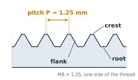
Metric thread pitch is the axial distance from a point on one thread crest to the corresponding point on the next crest. In a single-start thread, one full revolution advances the screw by one pitch relative to a fixed mating thread. For a typical callout, the nominal diameter is 8 mm and the pitch is 1.25 mm. A smaller pitch at the same nominal diameter means threads are closer together. It does not by itself make the fastener suitable for higher loads; material, geometry, and joint specifications must still match.
Threads per inch on Unified threads
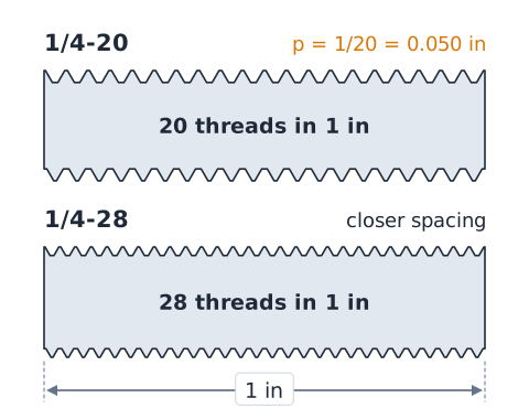
Unified thread notation often indicates nominal size followed by threads per inch (TPI). A designation describes a nominal quarter-inch thread diameter and 20 threads in one inch of axial length. Its pitch is
The number 20 is not 20 turns required for installation, and it is not a tightening-torque value. Compare it with , which has closer thread spacing. The pitch conversion is a useful short ASVAB arithmetic application.
Coarse versus fine threads
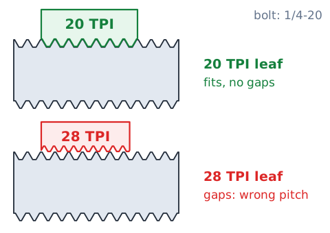
Coarse and fine refer to relative spacing within a given thread family and nominal size. Coarse threads usually have a larger pitch and fewer turns over a fixed distance; fine threads are more closely spaced. Coarse threads can be convenient in dirty service or soft materials in some designs, while fine threads may be selected for adjustment or certain engineered connections. Neither choice is universally stronger or safer. A 1/4-20 nut does not properly mate with a 1/4-28 bolt despite the matching nominal diameter. In a multiple-choice item, matching both diameter and pitch is essential.
Matching nut and bolt thread systems
A nut must match the external thread's diameter, pitch or TPI, thread form, and handedness, and meet the joint's required grade or class. Nominal metric and inch sizes can be close numerically but are not interchangeable. If a nut begins to bind unexpectedly, stop rather than forcing it with a longer wrench. Inspect for cross-threading, contamination, wrong pitch, or damaged starting threads. Finger-starting correctly aligned mating parts is a practical screening habit, not proof that a high-load connection is suitable.
Right-hand and left-hand threads
The common right-hand thread usually advances toward tightening when turned clockwise as viewed from the driving end. Left-hand threads tighten in the opposite direction and may be marked or used where the mechanism benefits from that direction. The correct action depends on which component turns and how the assembly is viewed. When diagnosing a resistant nut, consult the part specification before increasing force. In an exam, a left-hand thread is a deliberate exception rather than a manufacturing defect.
Single-start and multiple-start threads
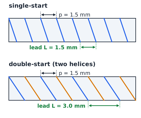
A single-start thread has one continuous helical ridge; its axial travel per turn (lead) equals its pitch. A double-start thread has two interleaved helices, so the lead equals twice its pitch. In general,
where is the number of starts. A double-start thread with
therefore advances
per turn. Distinguish pitch (neighboring crest spacing) from lead (travel per revolution); their equality is conditional, not universal.
Axial travel in an engaged screw
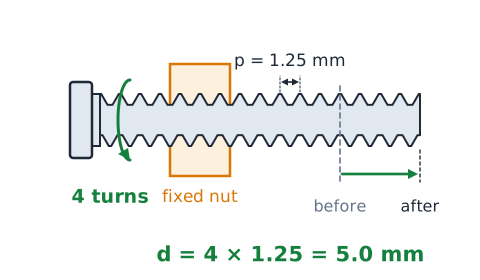
For an ideal engaged single-start screw, axial motion can be estimated by
where is number of turns and is pitch. Four complete turns of a 1.25 mm-pitch thread produce
of relative axial travel, assuming the mating part is restrained and the screw turns normally. A loose, stripped, or slipping thread would invalidate that assumption. Calculate travel before considering tightening force; displacement is not a direct measurement of clamp load.
Thread depth and the root
The crest is the outer raised part of a thread, the root is its valley, and the flanks are the inclined surfaces connecting them. Thread depth and profile determine mating contact and influence stress distribution. A tiny chip or nick at a root can matter more than a superficial mark on an unrelated surface, depending on the application. A thread gauge checks pitch but does not prove that the material or fastener strength meets specification. When inspecting a fastener, examine fit, damage, material markings, and application together.
Clearance hole versus tapped hole
A clearance hole lets the bolt shank or thread pass through without intentionally engaging the hole wall as a nut would. A tapped hole has internal threads cut or formed to mate with an external thread. Fastening two plates with a bolt and nut commonly uses clearance holes; fastening a cover directly into a threaded housing uses a tapped hole. Holes can have different fits or counterbores, so their drawing dimensions matter. Do not answer a question about fastening into a tapped part by automatically adding a separate nut.
Tapping internal threads
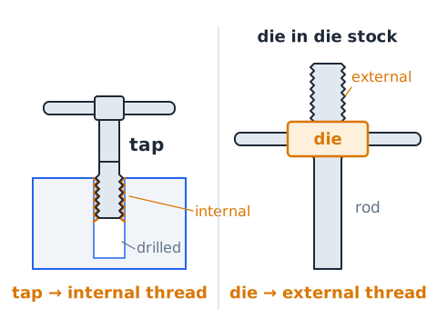
A tap is a cutting or forming tool used to create internal threads in an appropriately prepared hole; not all taps remove chips, so the tool type matters. A tap drill size must be suitable for the specified thread and material and is generally smaller than the nominal major diameter for typical cutting taps. Alignment, lubrication when appropriate, chip control, and correct tool handling prevent broken taps and damaged holes. A tap is not a die and should never be treated as a drill bit that creates every feature of the hole by itself.
Dies and external thread restoration
A threading die forms or cuts external threads on rod-like material using an appropriately sized and prepared workpiece. A thread-restoring tool may clean light damage, but it cannot make a significantly undersized or cracked part meet a strength specification. Start square, use controlled force, and obey manufacturer directions for lubrication and chip clearing. If the stem is a safety-critical stud with unknown damage, replacement or an approved repair procedure is more appropriate than improvising. Associate taps with internal threads and dies with external threads.
Thread pitch gauges
A thread pitch gauge carries leaves with tooth profiles marked by metric pitch or threads per inch. Match the leaf profile against clean, accessible threads without forcing it; then confirm diameter and thread standard. The gauge does not directly measure clamp force, grade, or full thread quality. Confusing the two common thread measurement systems is an avoidable examination error: a marking such as 20 TPI means 20 thread crests over one inch, not a 20 mm pitch. Always record the units together with the value.
Machine screws and self-tapping screws
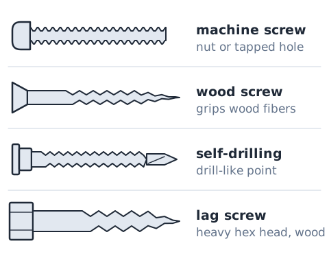
Machine screws use a defined machine thread and typically engage an existing nut or tapped hole. Some self-tapping or thread-forming screws create mating threads in a suitable material during installation. A self-drilling screw may also have a drill-like point, but self-drilling and self-tapping are not interchangeable labels in every product line. The correct screw depends on material thickness, hole preparation, edge distance, holding requirements, and manufacturer directions. In a Shop Information question, a pilot hole and material-specific screw are not automatically unnecessary.
Wood screws versus machine-thread screws
A conventional wood screw is shaped to grip wood fibers, often with a tapered point and a thread intended for the material. Machine-thread screws are generally made to mate with engineered internal threads or nuts. The same drive recess may appear on both; Phillips, Torx, and slotted describe a drive style, not the thread or intended substrate. In soft materials, an oversize hole can destroy holding capacity; a longer screw may help only if installation conditions support it. Select by application, not simply the appearance of the head.
Lag screws and structural attachment
A lag screw is a heavy, often hex-headed screw that engages wood or a suitable engineered anchor rather than a conventional nut. Proper pilot holes and embedment matter, especially near edges. The term lag bolt is commonly heard but does not mean it is installed like an ordinary bolt-and-nut assembly. Do not infer that lag screws are suitable for masonry or every structural connection without a designed anchor and approved instructions. On an exam, recognize the heavy wood-anchoring role while avoiding unsupported strength claims.
Head types and tool access
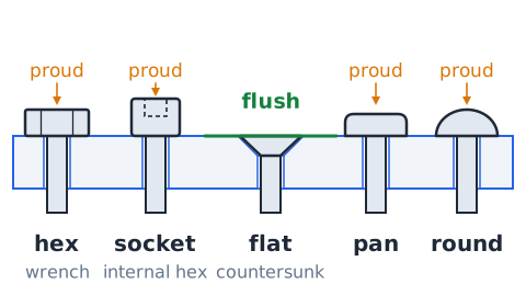
Hex heads accept a correctly sized wrench or socket; socket heads use an internal hex drive; flat or countersunk heads can sit flush when the matching countersink geometry is provided. Pan and round head styles generally remain proud of the surface. Head geometry may affect bearing area, clearance, appearance, and drive-tool choice. A countersink is not created by simply tightening harder. If a drawing requires a smooth sliding surface, choose the specified flush-head fastener and prepared hole instead of assuming any short bolt will fit.
Threaded stud and double-ended fasteners
A stud can remain installed in a housing while the detachable part is secured with a nut on its exposed end. This may reduce repeated wear of internal threads in a service part. Some double-ended studs have different threads at each end or are installed using specific methods. Do not substitute a generic all-thread rod solely because both pieces have external threads. The correct lengths, thread engagements, materials, and locking provisions depend on service requirements.
Flat washers
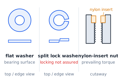
A flat washer can provide a bearing surface, protect the contact material, or span a suitably designed clearance opening. It does not automatically prevent loosening or compensate for a wrong bolt length. Large-diameter washers may be useful with a soft supporting material when specified, but choosing a random washer can reduce contact quality or interfere with joint geometry. Watch for washer location relative to the surface under the rotating nut or head. A washer's function is identified by shape and application, not by assuming every washer is a lock washer.
Spring washers and locking claims
Split lock washers are often described in basic tool catalogs as devices intended to resist loosening, but their effectiveness can be limited, especially in highly preloaded joints. Treat the claim of guaranteed vibration resistance as incorrect. Engineered vibration-resistant joints may require a prevailing-torque nut, adhesive, mechanical retainer, or other method validated for the conditions. The key distinction for an exam is purpose versus dependable performance: a lock washer is not a universal substitute for correct preload, fastener selection, and verification.
Lock nuts and prevailing torque
A prevailing-torque nut offers resistance to rotation beyond simple free-running engagement, sometimes through a deformed metal feature or polymer insert. It must be selected for the correct temperature, chemical environment, reuse policy, and thread geometry. A nylon-insert design is not automatically appropriate near high temperatures. A castle nut with a cotter pin provides a different form of mechanical retention. Identify the locking mechanism first; do not confuse the installation effort of a lock nut with achieved bolt preload.
Castle nuts and cotter pins
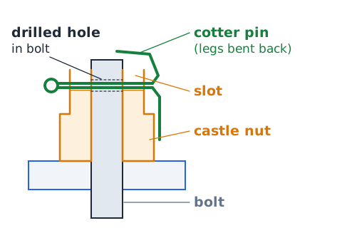
A castle or castellated nut has slots that allow a pin to pass through a matching drilled hole in the bolt or stud, preventing full rotation in the secured direction. The cotter pin is mechanically bent or retained according to the relevant procedure; a loose pin defeats the concept. Do not loosen or over-tighten a safety-critical assembly merely to align the pin unless the specified procedure directs it. A cotter pin is not used as the sole structural fastener for a heavily loaded joint.
Thread-locking compounds
Thread-locking adhesive may resist relative rotation when properly applied to compatible, clean mating threads and cured according to the product instructions. Strength grade, disassembly requirements, temperature, and exposure control selection. An adhesive cannot repair stripped metal threads or substitute for missing material. Some pre-applied products have different installation characteristics. In a question asking about vibration resistance, distinguish adhesive retention from the mechanical action of lock nuts or cotter pins; no one method suits every fastener.
Rivets and permanent fasteners
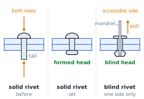
A solid rivet is plastically deformed to create a retaining head, while a blind rivet can be installed from one accessible side in suitable applications. Blind rivets are not automatically as strong as every structural solid rivet; their properties and installation are product-specific. A pin or rivet usually does not provide conventional threaded adjustability. If a question describes joining sheet material when only one face is accessible, a suitable blind rivet is a likely tool-shop answer, provided its specified strength is adequate.
Pins, dowels, and roll pins
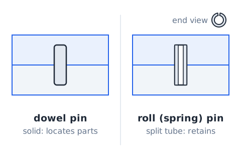
Dowel pins commonly locate components accurately; spring or roll pins can retain features through a designed hole; cotter pins often secure a slotted nut. Their installation methods and load roles differ. A dowel used for alignment does not replace a required clamping bolt unless the design provides for that load. The term pin alone does not tell you whether the connection is permanent or what force it can carry. Examine whether the stem asks about location, rotation prevention, removable retention, or clamping.
Bolt material and grades
Bolt material and specified grade or strength class affect tensile capacity and acceptable service conditions. Manufacturers may mark bolts or packages to identify a strength grade; markings must be interpreted under the applicable standard rather than by color alone. Some stainless fasteners resist corrosion in particular environments but may have different strengths or galling behavior. Replacing a marked structural bolt with an unmarked look-alike can be unsafe even when thread dimensions match. Use specified replacements, not guessed torque values or appearance.
Strength classes: avoid false equivalence
An ISO metric property class such as 8.8 is not the same notation as an SAE inch-based bolt grade. Numerical labels can be visually similar but the rating methods differ, and an 8.8 class bolt is not simply an SAE Grade 8 bolt. Joint selection involves material strength, thread geometry, fatigue, corrosion, and proof-load requirements. For ASVAB-level reasoning, recognize that a bolt must have both the correct thread fit and the required mechanical properties. A nut with a matching diameter alone cannot validate the joint.
Tension and shear loading
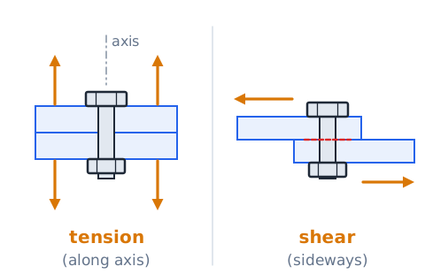
A tensile load pulls a fastener along its axis while a transverse shear load tends to slide parts sideways. Real joints can experience a mixture of these with bending, vibration, and fatigue. Proper clamping may transmit transverse force through interface friction, so it is misleading to assume a bolt always carries full sliding force in direct shear. A design must also consider edge distance, hole clearance, bearing surfaces, and member strength. The ASVAB typically tests recognition of force direction rather than detailed joint certification.
Preload: the squeezed-joint idea
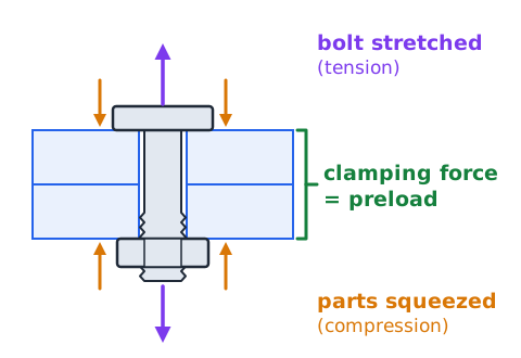
Tightening a threaded fastener normally stretches the bolt elastically and compresses the joint members. This initial clamping force is called preload. It can improve stability in a correctly designed joint, but too little preload may permit separation or movement while too much may damage the bolt or the joint. Exact preload is influenced by thread and bearing friction and cannot be read directly from the applied torque in a universal manner. Distinguish the tightening action, resulting clamping force, and external service load.
Torque is turning effort
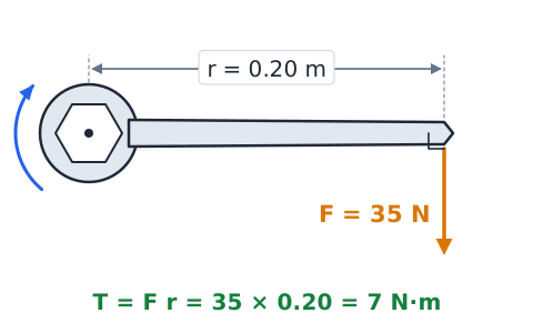
Torque magnitude for a perpendicular force is
where is force and is perpendicular lever arm. A push applied perpendicular to a handle gives
Force along the handle yields little turning effect. The calculation describes applied moment; it does not supply the manufacturer's tightening specification or directly determine actual preload. A proper torque wrench must be used according to the tool instructions and the service specification.
Force needed at a longer handle
Rearrange
to
when the force is perpendicular to the lever arm. If the required moment were 40 N·m and the effective handle length 0.25 m, the ideal force would be
Doubling the effective arm halves the force needed to produce the same torque. This is a mechanics calculation, not a reason to add a cheater bar to an ordinary wrench or exceed tool ratings. Do not infer that the fastener itself has become stronger.
Angle of force and lever arm
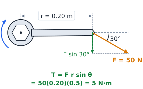
When the applied force is not perpendicular to the wrench, the moment magnitude is
with the angle between the handle and force direction. For a 50 N force on a 0.20 m handle at 30°,
The perpendicular component causes rotation; pulling axially along the wrench handle does not provide the full Fr moment. This distinction often appears as a diagram reasoning question.
Why published torque values matter
Tightening-torque instructions reflect fastener size, material, coatings, lubrication, joint design, and safety margins. A high torque value from another application cannot be transferred by matching only nominal diameter. Applying oil when the procedure specifies dry threads may alter friction and change preload at the same torque. An impact wrench is not a universal final torque measurement device. For wheel bolts or engineered machinery, rely on the specific approved service data, tool rating, and sequence rather than a guessed classroom formula.
Torque–preload relationships have uncertainty
Engineering models sometimes approximate torque with
where is target preload, nominal diameter, and an empirical nut factor combining friction effects. This simplified relationship is explanatory, not a substitute for verified assembly specifications. For illustration, if
then . Change lubrication or surfaces, and K may change significantly; the identical torque can lead to different actual preload.
Tightening sequences and gaskets
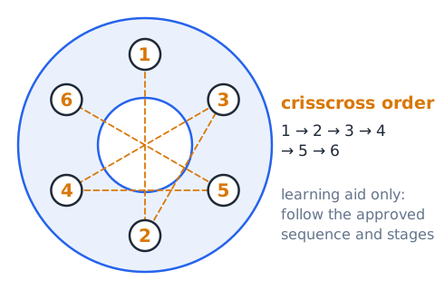
Multi-bolt covers, flanges, and wheel assemblies may require an alternating or specified sequence to distribute contact pressure evenly. Snugging and final tightening stages are not interchangeable with an arbitrary one-pass approach. Gaskets can be crushed or distorted by incorrect clamping and may need specified fasteners or service procedures. The familiar crisscross idea is a learning aid only; follow the actual approved sequence and stages for the assembly. In an exam situation, uneven tightening is a plausible contributor to poor seating.
Thread engagement length
Enough mating thread engagement is needed to transmit intended loads, but required length is not a fixed universal number of turns. It depends on bolt material, internal thread material, geometry, load, and design. A steel bolt in a soft alloy casting may call for different engagement details than a steel nut, and a bottomed-out screw can give misleading torque without properly clamping the joint. If the screw reaches a blind-hole bottom before seating, tightening harder does not correct the geometry. Select correct length and compatible threads.
Grip length versus overall length
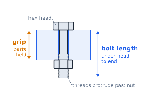
In a bolted joint, the grip is the thickness of material held together, while bolt length generally follows a specific head-to-end measurement convention. Correct bolt selection allows the parts to clamp while the nut or tapped hole engages as intended. A bolt can be long enough to look secure but bottom out in a blind hole or leave too few complete engaged threads. An excessively long bolt may also obstruct nearby moving parts. Different head types have different length conventions; do not assume all head styles measure from the same reference plane.
Shoulder bolts and bearing surfaces
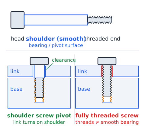
A shoulder screw has a precisely formed unthreaded portion used for spacing, guiding, or pivoting in suitable machinery. The threaded end secures it, but the shoulder can act as a bearing surface or controlled spacer. A standard fully threaded screw may not replace it because the threads do not provide the same smooth controlled diameter. In a diagram with a rotating linkage, look for a shoulder surface and intended clearance, rather than choosing simply the longest screw that fits.
Cross-threading and misalignment
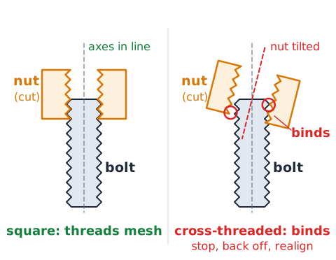
Cross-threading occurs when mating threads engage incorrectly, often from crooked starting alignment or incompatible profiles. Early resistance is a warning: stop, reverse carefully if appropriate, inspect, and realign. Never overcome the resistance by increasing torque with a power tool. A slightly damaged entry thread is not proof that the remaining thread has safe strength, especially for a critical joint. Finger-starting a clean assembly is useful as an initial check, while final service still requires the specified torque and inspection.
Stripped threads
Stripped internal or external threads have lost their load-carrying profile through damage or overloading. Typical signs are a nut that spins without clamping or flakes of thread material. Thread-locking adhesive, a larger washer, or extreme tightening cannot restore missing load-bearing metal. An engineered repair such as a specified threaded insert may be possible in certain assemblies, but it must follow approved dimensions and procedures. For critical components, seek an approved replacement or repair rather than guessing at interchangeability.
Threaded inserts and soft materials
A threaded insert can provide durable internal threads in a softer or damaged substrate when the engineered repair or original design permits it. Inserts differ: wire-type helicals, solid bushings, and other designs have different installation requirements. Incorrect hole drilling, tapping, or installation depth can make a repair weaker or misaligned. An insert is not just a nut pushed into a random hole, nor does it make every stripped safety-critical housing suitable for field repair. Read the assembly specification.
Galling and seizure
Galling is adhesive surface damage that can cause sliding metal surfaces—including some similar stainless fastener pairings—to seize during installation. Symptoms may include rapidly increasing resistance, tearing, or locked threads. Wrong pitch, debris, and cross-threading are alternative causes, so the symptom alone does not identify galling. Correct compatible materials, cleanliness, appropriate lubricants if specified, and controlled installation speed can reduce risk in a designed system. A longer wrench is not a safe diagnostic procedure for unknown resistance.
Corrosion and compatibility
Corrosion can reduce section thickness and impair disassembly or preload. Galvanic corrosion risk arises with certain dissimilar metals in a conductive environment; the degree depends on materials, surface area, electrolyte, and protective treatment. A stainless fastener is not immune to every corrosion mechanism. Coatings may protect a fastener but can change friction or other service properties. Material substitution must consider both strength and environment. A rusted head cannot be judged safe solely by measuring its remaining outside width.
Fatigue and repeated loading
A fastener subjected to repeated cycles can develop fatigue damage even when individual loads do not seem extreme. Abrupt geometric changes and thread roots concentrate stress, while incorrect clamp or joint slip can intensify cycling. A crack or elongated hole in a load-bearing connection is a reason for qualified inspection, not a reason to simply tighten the bolt harder. In ASVAB reasoning, identify a fluctuating load as different from a steady pull and recognize that material selection and joint design matter.
Choosing the correct wrench
Use a properly fitting wrench or socket on the specified drive feature. A six-point socket can be a useful choice when a fastener head is tight and rounding is a concern; the appropriate tool depends on fastener condition and accessibility. Adjustable wrenches need sound jaws and secure fit. OSHA prohibits use when wrench jaws are sprung to the point that slippage occurs. Improper extensions or hammering a nonimpact-rated tool may damage equipment. The ability to turn a fastener does not establish correct torque.
Impact drivers and final torque
An impact driver or impact wrench delivers repeated rotational impulses that help loosen or install some fasteners. It does not independently prove that final clamp load meets specification, and impact-rated accessories must be used as directed. Start threads properly to avoid cross-threading; stop if a fastener binds abnormally. For controlled critical tightening, follow the approved final-torque or angle procedure with a suitable calibrated tool. Question stems may tempt you to treat fast installation as correct installation; resist that shortcut.
Inspecting head and thread damage
Inspect damaged flats, cracked heads, corrosion, rolled or flattened threads, and missing retention devices. A visually normal head does not guarantee correct grade or preload, and a damaged driving recess may prevent proper removal. Use correct handling for sharp edges and chips. OSHA requires unsafe hand tools to be removed from use. A multiple-choice item about a rounded socket head most directly points to unsuitable tool engagement, not proof that the screw's pitch is wrong.
Stud removal and blind holes
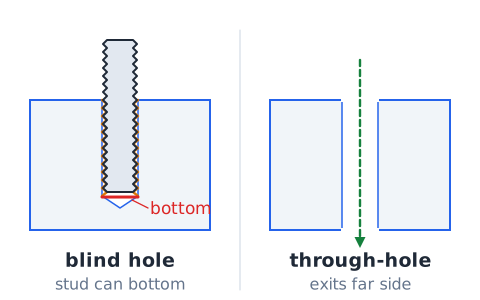
A stud may be installed to a specified depth in a tapped component, and excessive penetration can bottom the stud or damage the housing. A blind hole has a bottom; it differs from a through-hole that exits the far side. Contamination trapped in a blind hole may interfere with seating or affect fluid pressure during assembly. Consult approved cleaning and repair procedures. If the joint does not seat but the torque rises sharply, the correct response is to investigate thread fit and bottoming—not to add leverage.
Fastener callouts on drawings
A drawing may indicate thread system, nominal diameter, pitch or TPI, tolerance class, length, head type, material, grade, and finish. Interpreting only the diameter misses critical information. For example, M10 × 1.5 and M10 × 1.25 are different pitches even though both have the same nominal major diameter. A separate depth callout may apply to a tapped blind hole rather than the bolt. Always read surrounding notes instead of treating a designation as a complete universal purchase specification.
Metric versus inch measurement
Use the exact inch conversion
A nominal quarter inch corresponds to
which is not the same designation as an M6 metric thread. Similar diameters do not establish matching pitch or thread profiles. A metric ruler and a threads-per-inch gauge measure different things. On an exam, convert a stated length when asked, then check whether a question is about measured diameter, nominal thread identity, or allowable mechanical interchange.
Pitch as a decimal inch
For an inch-based single-start thread with TPI, pitch equals
At TPI,
Holding diameter constant, more threads per inch means smaller axial spacing. If a stem asks how far a nut advances in one ideal revolution, use the pitch for a single-start thread rather than multiplying by the thread count. These numbers are mathematical examples; they do not specify fastener grades or torque.
Metric screw revolutions to travel
An ideal single-start 1.5 mm-pitch screw must rotate
revolutions for travel . To advance 9 mm,
complete revolutions. The calculation presumes full engagement with a fixed mating component and ignores end stops. It is not a method for deciding whether a fastener is tight: a screw can advance the same distance under very different friction and joint conditions. Always distinguish kinematic travel from preload.
Thread count over a given length
For a uniform 20-TPI thread, a one-inch axial section spans approximately 20 pitches and a half-inch section spans approximately 10. In general, the ideal count of pitches is
with length in inches. The exact visible number of crests at section ends can depend on where you begin and stop counting, but pitch calculations are unambiguous. Avoid interpreting TPI as torque or as a diameter dimension. Compare the units before doing arithmetic.
Load sharing is not automatically equal
Several bolts in a joint do not necessarily share applied loads equally. Joint stiffness, distance from the applied load, eccentricity, contact, and installation variations influence the distribution. It is unsafe to assume that four bolts always divide any load by four in a real connection, even though a classroom toy model may specify equal sharing explicitly. A Shop Information test may ask about fastening methods rather than full stress analysis. If a mathematical question states equal sharing as an assumption, follow it; otherwise avoid pretending the assumption is guaranteed.
Fastener selection: decision path
Begin with the function: removable clamp, position alignment, pivot, sheet joining, or one-sided access. Then identify the material and hole form, load direction, vibration and environment, thread standard, space, and service requirements. Match size, pitch, handedness, strength, and locking method to authoritative specifications. Inspect the tool and fastener before use. The correct answer is rarely 'use the biggest bolt available'; over-sized holes can weaken parts and unapproved modifications can introduce failures. For the exam, justify each selection with the feature stated in the question.
Common misconception: diameter equals compatibility
Two parts can look similar in diameter while having different pitch, thread shape, tolerance, or handedness. A nut that starts one turn and then jams should not be forced to prove compatibility. Even a matched thread size does not prove strength class suitability. A useful elimination method is to reject any answer claiming interchangeable fasteners solely from outside diameter or wrench size. Choose a correct mate that matches the complete thread designation and service specification.
Common misconception: more torque always helps
A fastener can fail from insufficient tightening, but extra torque can also stretch it beyond its intended range, damage internal threads, crush a gasket, or distort a component. Torque is a controlled installation variable, not a universal measurement of remaining service life. An impact wrench setting is not a certified tightening procedure. If a question describes a joint that does not clamp despite increasing wrench effort, suspect wrong length, stripped threads, or bottoming rather than assuming even more effort is correct.
Common misconception: washers cure wrong fit
A washer may change the bearing interface or assist with a specified assembly, but it does not correct mismatched thread pitch, wrong grade, unsafe length, or stripped threads. Extra washers may alter thread engagement or interfere with intended geometry. When presented with a bolt that binds in the wrong nut, replacing the nut with one of correct thread designation is generally more relevant than adding washers. An exam distractor often names a legitimate shop part but assigns it an unrelated job.
Guided identification: five objects
Picture a hex-head bolt with a nut, a countersunk screw in a tapped block, a smooth dowel in an alignment hole, a blind rivet in thin sheet, and a cotter pin retaining a slotted nut. First name each object and then state its function: clamp removable plates, fasten with a flush head, locate two parts, join sheet from one side, or prevent nut rotation. Swap the functions deliberately to see why the incorrect choices fail. This is stronger preparation than simply memorizing the appearance of tool catalog items.
Guided calculation: three thread systems
Work three independent identifications: gives a nominal 0.25-inch diameter and 0.050-inch pitch; gives a nominal 8 mm diameter and 1.25 mm pitch; and a two-start 1.0 mm-pitch screw gives
travel per turn. Say the units aloud as you identify each value. This prevents accidentally treating TPI, metric pitch, nominal size, and lead as the same concept.
Guided diagnosis: a binding nut
You finger-start a nut, but it binds after part of a turn. Separate possible causes: wrong thread pitch, cross-threading, dirt or burrs, or damaged threads. Identify a safe next step: stop and inspect the markings and mating surfaces rather than adding force. A different wrench does not repair alignment. In a multiple-choice problem, prefer an answer that tests or restores compatibility; reject one that assumes the nut will 'cut its own threads' unless it is explicitly a designed thread-forming component.
Guided safety: the loose handle and cracked socket
Imagine a hammer with a cracked wooden handle, a wrench with jaws spread so it slips, and a socket with a visible crack. The safe action is not to improve your grip or strike harder: remove unsafe tools from service under the applicable workplace procedures. OSHA specifically addresses damaged wrench jaws and broken or loose wooden handles. Know the difference between a normal removable component and a damaged item that compromises control. This general safety concept belongs in the Shop Information domain.
Guided torque exercise
A student applies a perpendicular 80 N force at the end of a 0.15 m wrench. The moment is
If the handle length doubles and the desired torque stays the same, the needed perpendicular force halves. Do not treat the calculated 12 N·m as an appropriate torque for any real fastener; only the problem's force and geometry determine it. This exercise links shop terminology with basic Mechanical Comprehension, but its result is not a service specification.
Before tightening: a practical check
Confirm the correct fastener designation, grade, length, hole condition, mating material, tool, and sequence. Verify that the threads start freely and seat correctly where that is expected. If the procedure calls for lubrication, locking compound, or a specified washer, follow it rather than improvising. Wear task-appropriate protection and keep tools in safe condition. The check applies especially when replacing a removed fastener that may have special locking or reuse instructions. Treat unexpected resistance as diagnostic information.
Final ASVAB recall checklist
Recall the distinctions that earn fast points: bolt plus nut versus screw into tapped material; tap for internal threads and die for external; metric pitch in millimeters versus inch TPI; lead equals pitch only for a single-start thread; flat washers provide bearing support while retention devices have distinct functions; preload differs from torque; a mismatched nut should never be forced; and proper grade, length, and corrosion compatibility matter. Use the stem to decide whether the problem asks for part identification, geometric travel, turning moment, or safe handling.
 English ▾