 ASVAB Camp
Lesson objective and exam boundary
This Shop Information lesson explains what a drill press, grinder, lathe, mill, band saw, and related machines do, how their motion differs, and how a shop worker reasons about setup, dimensions, and hazards. On the ASVAB, recognition of names, operations, safe shop practices, and simple physical relationships matters more than expert machine programming. The examples are independently written for study, not copied from secure ASVAB questions. Treat equipment-specific setup as supervised training rather than a substitute for manufacturer instructions.
A machine is a combination of motion and tooling
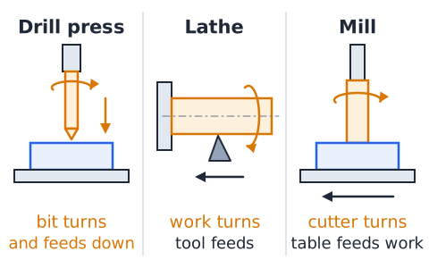
Start with the relative motion of cutting edge and work. Drilling typically rotates a bit into stock; a lathe rotates the work and feeds a tool; milling rotates a multipoint cutter while a workholding table or tool advances. Grinding removes material with abrasive grains rather than large cutting teeth. These distinctions make tool identification more reliable than guessing from the silhouette of a machine or its color. Different configurations can accomplish overlapping jobs.
Primary operations: shape, hole, surface
To identify the right machine, first identify the final feature. A cylindrical bore suggests drilling or boring. A very smooth flat surface may call for grinding. External cylindrical steps typically suggest turning. A wide flat face, slot, or pocket suggests milling. Sawing divides stock. Machines may overlap, and the correct selection also depends on material, accuracy, geometry, batch size, and the workholding available. An ASVAB-style question usually isolates the most characteristic operation.
Drill press: fixed spindle and supported table
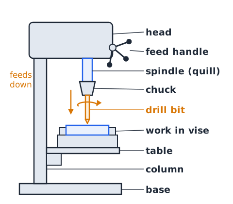
A drill press has a motor-driven spindle or quill that feeds a rotating drill bit toward stock supported on a table. Its rigidity helps keep a hole aligned compared with casual hand drilling. The base, column, table, head, chuck, and feed handle have different functions: the table supports a fixture, and the chuck grips the correct drill shank. A drill press is not a lathe; the typical workpiece does not rotate during drilling.
Workholding before drill rotation
A drill bit can grab a workpiece, abruptly turning an unsecured part into a projectile. Use a suitable vise or clamping fixture and inspect clearance below the hole path. Secure work rather than holding it by hand, especially for small or irregular parts. Keep the guard and other manufacturer-specified protection in place. Pause the machine before measuring, clearing chips, changing tooling, or adjusting clamps. Shop practice is to plan the restraint before applying power.
Chuck keys and tool changes
A keyed chuck is tightened with its proper key, which must be removed before the spindle starts. A key left in the chuck can be ejected by rotation. Keyless chucks have different operating instructions, but the no-loose-tools principle remains. Switch off and isolate the machine where required before accessory replacement or servicing. Confirm the bit is seated and compatible with the chuck; a damaged bit is not repaired by simply tightening harder.
Twist drill geometry
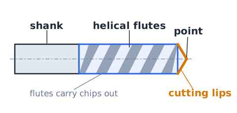
A common twist drill has a point, cutting lips, helical flutes, and a shank. The lips remove stock; the flutes provide paths for chips and some coolant. A sharp point and suitable geometry help centering and cutting, but different materials may require different point angles or coatings. The flute is not a screw thread for fastening. A drill bit is a cutting tool, while a center punch or spotting operation helps locate the intended hole.
Pilot holes: purpose and limits
A pilot hole is a smaller initial hole that can guide later drilling, reduce thrust demands for a suitable process, or help establish location. Pilot holes are not universally necessary, and in some materials or small sizes they can increase wandering or produce undesirable tool loading. Choice of pilot diameter, bit type, and sequence follows the job procedure. The test-worthy idea is that pilot drilling prepares the feature; it does not necessarily produce the finished dimension.
Through holes versus blind holes
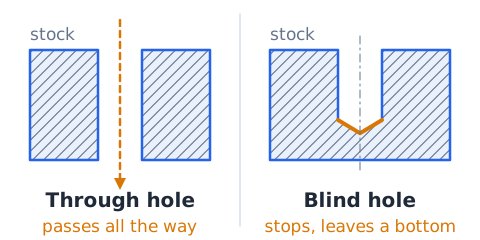
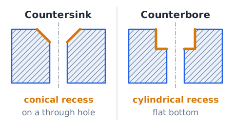
A through hole passes completely through the stock. A blind hole stops within the material and leaves a bottom. Depth control matters especially for blind holes; a machine operator must account for point geometry, chips, and the actual drawing requirement. A counterbore is a larger cylindrical recess at the opening; a countersink is a conical recess. Neither term means the entire bore is tapered. Identify the picture of the required hole before selecting the operation.
Reaming versus drilling
Drilling creates or enlarges a hole but may not achieve the most precise finished diameter or surface. A reamer is designed to refine a previously prepared hole by removing a small amount of stock. Reaming is not a cure for severe hole mislocation, nor is it usually intended to remove the bulk of the hole material. When a question emphasizes improving an existing bore to a close finished size, reaming is the characteristic answer.
Boring: adjust an existing hole
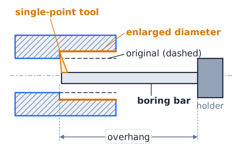
Boring enlarges or refines an existing hole with a single-point cutting tool or specialized boring head. On a lathe or mill, boring can improve coaxiality or diameter under suitable setup. The term should not be confused with merely drilling a fresh hole through solid material. A boring bar extends into an existing opening, so rigidity and overhang affect vibration and finish. A diagram with a single tool cutting the inside diameter usually signals boring.
Tapping and threading around drilled holes
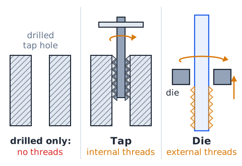
A tap cuts or forms internal screw threads in a correctly prepared hole, while a die commonly makes external threads. Drilling the tap-hole size is a preparatory step: drilling alone does not produce usable threads. Tap drill size depends on thread specification, material, and tool/process choice, and a nominal bolt diameter must not be assumed to equal tap-drill diameter. The exam distinction is between producing a plain drilled hole and making the internal helix that engages a bolt.
Drill diameter versus hole size
Drill size commonly refers to nominal cutting diameter, but the produced hole can vary with tool condition, alignment, material, feed, and machine rigidity. A hole specified as 8.00 mm must be inspected against drawing tolerances; selecting a nominal 8 mm drill by itself does not guarantee an 8.00 mm final bore. Inspection tools include calipers for approximate checking and suitable gauges or bore-measuring instruments for closer requirements. Never assert precision without measurement.
Feed: how far a drill advances
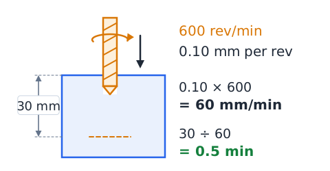
Feed describes advancement into the material; a common drill feed unit is millimeters per revolution (mm/rev). Multiply feed per revolution by rotational speed in revolutions per minute to find ideal linear feed rate in millimeters per minute. This is a theoretical kinematic relation, not permission to use any particular machining setting. Changing feed affects chip formation and tool load; recommended values depend on material, bit geometry, machine, and job instructions.
Drilling feed calculation
For illustration, a drill turns at 600 revolutions per minute and the specified feed is 0.10 millimeter per revolution. Multiply 600 by 0.10 to obtain an ideal advance rate of 60 millimeters per minute. At a constant rate and ignoring approach, retract, and interruptions, 30 millimeters of feed travel takes 0.5 minute. A test may use different units; write down the units before multiplying to avoid confusing millimeters per revolution with millimeters per minute.
Rotation speed: RPM does not equal surface speed
RPM counts spindle revolutions per minute. Cutting speed is linear travel at the outside diameter; a larger diameter makes more linear travel per revolution at the same RPM. Consequently a diameter change can require an RPM change to maintain a selected cutting speed. Tool and machine limits always take priority over classroom arithmetic. Do not transfer a setting from a small drill directly to a large hole without considering material and diameter.
Surface speed at a drill edge
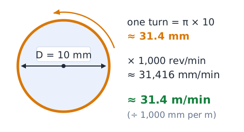
For ideal circular motion, circumference equals π times diameter. Multiplying circumference by RPM gives distance per minute at the circumference. With diameter in millimeters, divide by 1,000 to express meters per minute. For a 10 mm diameter tool at 1,000 RPM, cutting speed is approximately 31.4 m/min. This relationship explains why the edge of a larger diameter tool travels faster at the same RPM.
Solve RPM from cutting speed
If a target cutting speed is stated in meters per minute and diameter in millimeters, rearrange the surface-speed formula: RPM equals 1000 times cutting speed divided by π times diameter. At 30 m/min with a 10 mm tool, RPM is about 955, before choosing a permissible machine setting. Actual settings require material-specific information and safe machine limits; this calculation merely tests understanding of circular motion and unit conversion.
Metric and inch drill sizes
Shop drawings and tool racks can use metric or inch measures. The international inch equals exactly 25.4 millimeters, so a 1/4-inch nominal bit is 6.35 mm. That exact unit conversion does not mean a 6 mm bit is interchangeable with a 1/4-inch bit when tolerances matter. Letter and numbered drill sizes also exist; do not assume that a drill size number is literally the same number of millimeters or inches.
Locating a hole accurately
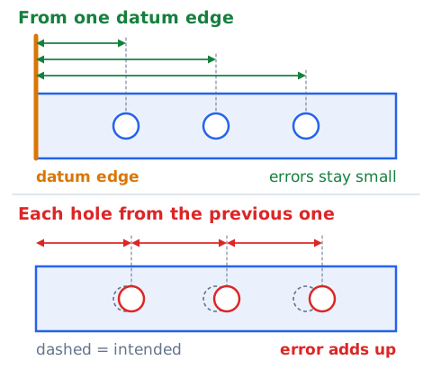
Before drilling, use a drawing datum or measured reference edge to locate the intended center. Layout dye, marking, a center punch where suitable, or spotting procedures can help a twist drill begin at a designated point. Incorrectly measuring each successive hole from the previous one may accumulate error. Machine coordinates and clamping geometry are distinct: a visually centered clamp does not prove that the tool is positioned at the drawing datum.
Burrs after hole making
Drilling may leave raised edges or burrs near the entrance and exit of a hole. Deburring removes sharp projections so parts fit and people are less likely to be cut. A countersink may remove a small entrance burr, but a designed countersink recess is not synonymous with arbitrary deburring. Inspect the finished part for dimensional and edge requirements. Never reach into rotating machinery or brush chips away with bare hands; stop and use an appropriate removal tool.
Portable drill: what changes
A hand-held drill offers mobility, whereas a drill press better supports accurate, repeatable positioning of a restrained workpiece. Portable drills require particular attention to operator stance, torque reaction, cords or batteries, and the condition of the bit. Tool controls and guarding depend on model and regulation. A powered drill is not inherently safe merely because it is smaller than stationary equipment; unexpected bit binding can rotate the housing forcefully.
Angle drill and impact driver differences
An angle drill redirects the drive axis to work in tight spaces. An impact driver applies repeated torsional impacts for suitable fasteners, whereas a drill is optimized for rotating a cutting bit and may include a clutch for driving screws. Some combination tools can do both, but not every chuck accepts every accessory. Exam questions often contrast making a hole with driving a screw; the desired action determines the most characteristic tool.
Bench grinder: abrasive cutting action
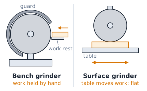
A bench grinder rotates bonded abrasive wheels to remove small amounts of material, sharpen suitable tools, or clean edges when proper wheel and task selections are made. Each grain acts as a tiny cutting point. Unlike a toothed milling cutter, an abrasive wheel is a consumable surface that wears. Guarding and suitable eye/face protection matter because sparks and fragments can be ejected. Do not use a wheel in a manner its manufacturer prohibits.
Offhand grinder work rest limit
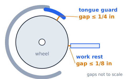
For the offhand grinding machines covered by OSHA 29 CFR 1910.215(a)(4), the adjustable work rest supports the work and must be set close to the wheel, with a maximum opening of one-eighth inch. The stated rule also says the work rest must not be adjusted while the wheel is moving. A larger gap can let a workpiece jam between rest and wheel, potentially breaking the wheel. This is a rule for its specified equipment context, not a universal measurement for all grinding processes.
Upper tongue-guard opening
For covered abrasive wheel machinery with a front operator opening, OSHA 29 CFR 1910.215(b)(9) separately limits the adjustable tongue or top peripheral-guard opening to no more than one-fourth inch. It is not the same component as the work rest: the rest is below the operator contact zone; the adjustable tongue is above. A question that swaps the 1/8-inch and 1/4-inch values is testing whether you identified the correct opening.
Grinder guards and wheel rating
A wheel’s marked maximum operating speed must not be exceeded by the machine spindle. Inspect wheel condition and use the guard and mounting system appropriate to the wheel and grinder design. OSHA has detailed requirements for certain abrasive wheels, including pre-mount inspection. Wheel types and exceptions matter, so a general statement that every wheel uses identical guards is inaccurate. Never substitute an improvised fastener, remove a guard, or assume a crack is harmless.
Wheel defects and safe response
An abrasive wheel that is cracked, damaged, or otherwise questionable should not be operated. Inspect it per manufacturer procedures and applicable regulations; certain wheels require a suitable ring test before mounting. Poor storage and impacts can create hidden damage. If vibration develops unexpectedly, stop the machine using its normal controls and seek qualified evaluation after it stops. Inspecting or adjusting a wheel while it rotates exposes a worker to avoidable danger.
Grinding sparks and personal protection
Grinding can generate sparks, dust, and flying abrasive or metal particles. Select task-appropriate protective eyewear, face protection as needed, guards, clothing, and controls for adjacent combustibles. A face shield often supplements rather than replaces proper eye protection. Loose sleeves, jewelry, and hair near rotating machinery create entanglement risks. Protect nearby people from projected particles; safe practice includes planning the work area, not just protecting the operator.
Metalworking fluids and heat
Cutting or grinding fluids can assist with cooling, lubrication, chip transport, and corrosion control depending on process and formulation. They also introduce exposure and housekeeping concerns: mists, skin contact, slips, and improper disposal. NIOSH describes respiratory and skin issues associated with certain metalworking-fluid exposures. The fluid must be suitable for material and process; never presume that water or any household oil is an acceptable coolant for every shop machine.
Surface grinder versus bench grinder
A surface grinder uses an abrasive wheel and a precisely supported table motion to create accurate flats under an appropriate setup. A bench grinder is more commonly associated with offhand sharpening or deburring. Both involve abrasive action, but their holding and feed arrangements differ. A test that says a flat precision finish is required usually points toward surface grinding, whereas a handheld piece brought to a stationary wheel suggests bench grinding.
Cylindrical grinding and centerless grinding
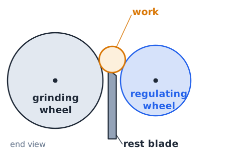
Cylindrical grinding refines the exterior of round stock and may use centers or chucks. Centerless grinding supports the work between a grinding wheel, regulating wheel, and rest blade without conventional centers. Both are specialized finishing methods, not just another name for drilling or turning. Recognizing that the goal is precise round surface finishing often answers the question even if the detailed grinder geometry is unfamiliar.
Grinding wheel speed and diameter
Wheel-edge speed uses the same circumference relationship as other rotating tools. If a wheel rotates at 1,500 RPM with a 0.20 m diameter, the outer speed is about 942 m/min. This illustrates why wheel rating, guard integrity, and inspection are critical. The calculation does not tell you that the wheel is safe at that speed: safe operation depends on the rated wheel, machine, mounting, material, and manufacturer procedures.
Lathe essentials
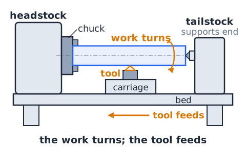
A lathe principally rotates a workpiece held by a suitable chuck, collet, or between centers while a cutting tool advances. Typical turning operations produce outside diameters, facing produces an end surface, and a boring bar can machine inside a hole. The tailstock can support long stock or hold a drilling tool. Never confuse the rotating work in a conventional lathe with the rotating cutter of a typical milling machine.
Lathe facing and turning
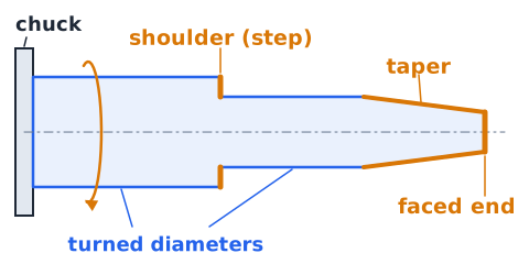
Facing commonly cuts across an end face to establish a surface normal to the rotation axis. Turning removes material along an outside cylindrical surface to reduce or shape diameter. A taper has a changing diameter; a shoulder separates diameters at a step. The operator must plan workholding, tool travel, and chuck clearance, rather than assuming any tool movement is safe. ASVAB questions often describe the finished geometry instead of naming the operation.
Lathe workholding and entanglement
The rotating chuck and stock can snag loose items. Keep hands, measuring tools, and clothing away from moving work; remove the chuck key, close appropriate guards, and stop before setup, inspection, or chip removal. Long protruding stock requires proper support and guarding. A metalworking lathe is not a device for gripping a rotating part by hand. Supervised instruction and manufacturer requirements govern real operation; this lesson teaches recognition and safety concepts.
Milling machine: rotating cutter
A mill commonly rotates a cutter while the stock is secured to a table or fixture. End mills can create pockets, shoulders, slots, and side walls; face mills address broad flat surfaces. Cutter teeth remove discrete chips. Feed may come from the machine table or tool, so the phrase rotating cutter is the strongest identification clue. Guarding must account for the rotating tool, flying chips, and workholding.
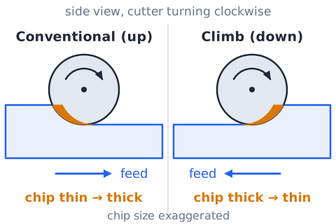
Climb versus conventional milling
In conventional (up) milling, typical chip thickness grows during engagement; in climb (down) milling it generally decreases. Tool motion relative to feed distinguishes them, but modern practice and recommended selection depend on rigidity, backlash, cutter, and work. Beginners should identify the words as direction-of-engagement terminology, not memorize a universal rule that one is always safer or better. Questions must specify the viewpoint to make direction diagrams unambiguous.
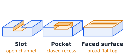
Slotting, pocketing and facing
A slot is an elongated channel; a pocket is a bounded recess; a faced surface is a broad flat area. An end mill may perform several operations, while a large face cutter is optimized for broad flat stock. A drill usually creates a round hole along its axis and does not automatically substitute for side milling. Real selection depends on cutter design; the simplified ASVAB concept is to match the machine and operation to the shape.
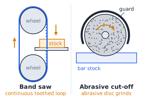
Band saw and abrasive cut-off wheel
A band saw uses a continuous toothed blade running on wheels to cut stock. An abrasive cut-off wheel grinds through material, while a toothed cold saw or band saw shears chips. Wheel selection and guarding are not interchangeable. In a test, continuous loop blade points toward band saw; a circular bonded abrasive disc points toward abrasive cutting. Material type and thickness determine the actual choice.
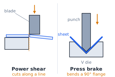
Power shear and press brake
A power shear cuts sheet along a line; a press brake bends sheet to an angle using matched tooling. They do not have the same purpose, even though both may process sheet metal and use presses or frames. Guarding must account for pinch and point-of-operation hazards. A question about reducing sheet width suggests shearing, while making an L-shaped flange suggests bending on a press brake.
Hydraulic press use and limits
A press applies large controlled force for suitable forming, pressing, or bearing installation jobs using designed fixtures. It is not simply a high-powered drill or grinder. Load paths, alignment, rated capacity, ejection hazards, and guarded pinch points matter. For educational problems, distinguish force-producing machines from material-removing machines. Never treat a calculated hydraulic force as permission to exceed equipment rating or ignore tooling limitations.
Arbor press and drill press are different
An arbor press pushes with a manual or mechanical ram and is often used for installing or removing press-fit parts with proper support. A drill press rotates a cutting tool while feeding it axially. Both have vertical-looking shafts but deliver different actions. Read the job verb: press a bushing into place points to a press; create a round hole points to a drilling operation.
Bench vise versus machine vise
A bench vise secures stock during suitable hand work; a machine vise is designed to hold stock on a mill or drill press under controlled cutting loads. Jaw shape, mounting, and precision differ. Do not use a vise designed for one application as an unverified substitute for another. Clamping alone is not enough if work protrudes into a tool path or setup leaves insufficient clearance. Support and fixture design help prevent movement.
Machine guarding: hazards and purpose
OSHA 29 CFR 1910.212 addresses hazards such as point-of-operation exposure, rotating parts, incoming nip points, and flying chips or sparks. Guards or protective devices must suit the hazard. A transparent chip shield is not necessarily a substitute for required guarding, and a stop switch does not alone replace guards. The key classroom principle is to anticipate where contact or ejection can occur during normal operation and foreseeable failure.
Power isolation and unexpected startup
A switch in the off position is not always sufficient for servicing equipment that could unexpectedly energize or release stored energy. OSHA 29 CFR 1910.147 addresses covered servicing and maintenance involving hazardous energy, with exceptions and defined procedures. For routine tool changes and maintenance, follow the applicable machine and energy-isolation instructions. This is different from the ordinary act of shutting off power at the end of a cut.
Chip handling and housekeeping
Machining produces chips that may be sharp and hot. Wait for equipment to stop; use a brush or approved chip hook instead of a bare hand, and wear proper protective equipment. Clear spilled coolant, keep walking surfaces clean, and maintain a defined area for hot chips and scrap. Do not use compressed air without evaluating applicable rules, eye hazards, and airborne particle risks. Good housekeeping prevents cuts, slips, and hidden fixture interference.
Inspection: dimension and surface finish
A nominal tool diameter or feed setting is not proof that the finished part meets the drawing. Inspection checks holes, positions, surface condition, and relevant tolerances. A caliper may verify general dimensions; a micrometer, pin gauge, or bore gauge may be more suitable for close features. Surface finish is not identical to dimensional accuracy: a smooth hole can still be too large or misplaced.
Runout, deflection and tool chatter
Runout means rotation is not perfectly concentric with the intended axis; deflection means a tool or part bends under load. Chatter is self-excited vibration often evident as noise or patterned finish. All can impair dimensional accuracy, but their causes are not interchangeable. A bent tool, poor holder setup, excessive overhang, and unstable clamping can contribute in different ways. Diagnosis requires observation and inspection, not an immediate assumption about a single faulty component.
Tool wear signs and interpretation
A worn cutting tool can increase cutting force, worsen finish, and create excess heat. A chipped tooth, dull lip, or glazed abrasive surface has a different remedy, and none should be ignored. Never sharpen, dress, or adjust a running tool by improvisation. Determine the condition only after the machine has stopped and the required safe procedure is followed. On an exam, distinguish wear symptoms from the name of the tool.
Diameter and tolerance interval example
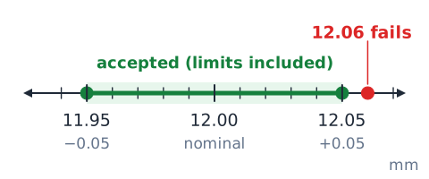
A drawing calls for a 12.00 mm hole with tolerance ±0.05 mm. The lower acceptable value is 11.95 mm, and the upper is 12.05 mm, assuming inclusive tolerance limits. A measured 12.06 mm fails the upper limit even if it looks smooth. The drawing, not the drill nominal size, defines the finished tolerance. With a different asymmetric tolerance, calculate the lower and upper ends separately.
Volume of drilled-away cylinder
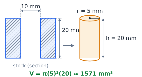
In a simple idealized geometry problem, material removed by a through hole equals the volume of a cylinder, πr²h, ignoring entry/exit shape and chips. A 10 mm diameter through hole in 20 mm thick stock removes about 1,571 mm³. It is important to use radius (5 mm) rather than diameter in the squared term. Actual machining calculations can incorporate allowance and different geometry, but the basic volume test is useful for dimensional reasoning.
Areal contact and pressure
Pressure is force divided by contact area. If an ideal fixture distributes 1,200 N over 600 mm², the average pressure is 2 N/mm², equal to 2 MPa. This does not guarantee the fixture is suitable because local contact, material strength, machine load, and work geometry may be unequal. In a test, units help reveal errors: force is in newtons and pressure is force per unit area, not force multiplied by area.
Shop math: cutting travel time
At constant feed rate, cutting time is travel divided by feed speed. If a tool travels 45 mm at 90 mm/min, the ideal travel time is 0.5 min or 30 seconds. A real process includes positioning, acceleration, pecking, retracting, inspection, and machine cycle overhead. Exam arithmetic often deliberately excludes these factors. Read whether the question asks theoretical cutting time or elapsed production time.
Convert surface speed from millimeters
A circular edge 100 mm in diameter has an ideal circumference of about 314.16 mm. At 300 RPM its edge travels about 94,248 mm/min, or 94.25 m/min. Converting units at the end reduces confusion. The formula uses the same πD principle for a drill, turning workpiece, or grinding wheel, but the correct rotating diameter depends on which part of the process is moving.
Machine selection decision example
Suppose a steel bracket needs one 8 mm through hole, a shallow countersink, and final deburring. A supported drilling operation creates the through hole, a countersinking tool forms the conical recess, and a controlled finishing tool removes remaining burrs. A surface grinder or lathe is not the normal first choice for this simple hole sequence. Drawings and tolerances may change process choices; the lesson teaches operation recognition, not a fixed recipe for every bracket.
Machine selection decision: shaft
Suppose a round shaft needs an external cylindrical shoulder followed by improved finish. A lathe turning operation is characteristic for changing the shoulder diameter; a suitable grinding process may refine finish or dimension where specified. Drilling would mainly produce axial holes, not the outside step. A test asking which machine spins the workpiece relative to a cutting tool often points to the lathe.
Machine selection decision: slotted plate
A plate needs a straight-walled rectangular slot. A milling cutter is a common way to remove the slot material after proper fixturing and process selection. A drill can create a round starting hole but is not, by itself, the usual tool for producing straight side walls. Band sawing or other methods may be feasible in specialized circumstances; identify the most characteristic operation rather than insisting on only one possible industrial method.
Machine selection decision: fine flat finish
A broad machined plate surface must be finished to a specified flatness and low roughness. A suitable surface grinding operation can serve that purpose after other stock removal. Merely cutting with a hacksaw or drilling holes does not directly satisfy a broad flat finishing requirement. Note that grinding is not automatically necessary for every flat face; tolerances, material, finish, and process capability determine whether milling alone suffices.
Common trap: all rotary machines are drills
A drill press rotates a tool to cut an axial hole, a lathe rotates a workpiece to turn a surface, and a mill rotates a cutter to machine many geometric features. A grinder uses rotating abrasive grains. The phrase it spins is not enough to identify a machine. Ask what rotates, what is being cut, and what finished feature results. This three-part check eliminates many wrong answer choices on tool identification questions.
Common trap: RPM is a material property
RPM is a rotational setting, not a metal hardness value or a speed that is safe for every wheel. Linear edge speed also depends on diameter. A material, tool geometry, coating, wheel rating, and machine design may impose different limits. When an arithmetic item supplies values, compute the requested quantity without inventing an allowable cutting-speed recommendation. Units and manufacturer ratings are part of sound shop reasoning.
Common trap: the two grinder gaps
The work rest supports a piece below the grinding contact area; the adjustable upper tongue guard covers part of the exposed wheel. For the covered bench/floor grinding configurations, the OSHA work-rest opening is at most 1/8 in, while the top tongue opening is at most 1/4 in. Neither is a rule that permits removing side guards. Do not move either adjustment while the wheel is running; follow the equipment-specific safe procedure.
Common trap: a blind hole is a countersink
A blind hole merely does not pass entirely through material. A countersink is a conical recess near a hole opening, while a counterbore is cylindrical. A single part can contain a blind hole with a countersink, but the features are different. Interpret geometry from cross-section and keywords, not from memorized word fragments.
Guided check: choose the correct motion
Question: A cutter spins while a table feeds a clamped workpiece sideways to make a slot. That is characteristic of milling. If the workpiece itself spins and a tool moves longitudinally to form a shaft diameter, that is characteristic of turning. If a rotating twist drill advances along its axis into restrained material, that is drilling. Practice this classification until you can answer without relying on machine pictures.
Guided check: work rest setup
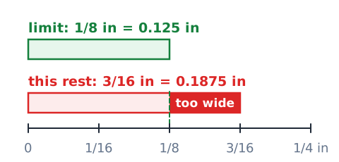
Question: A covered offhand bench grinder has an adjustable rest that is 3/16 inch from its wheel. Compare 3/16 (0.1875) with 1/8 (0.125). The opening exceeds the applicable work-rest limit. The correct response is to have the rest adjusted using a safe stopped-machine procedure before operation, not to reach toward it while rotating. Do not confuse this with the distinct 1/4-inch upper tongue clearance.
Guided check: unit conversions
Question: A nominal 3/8-inch drill corresponds to how many millimeters? Multiply 0.375 by 25.4 to get 9.525 mm. A rounded 9.5 mm is not always interchangeable with the specified inch-size bit, especially when the drawing requires close tolerances. Numeric conversion preserves the magnitude; acceptable tool substitution requires a separate dimensional and process check.
Guided check: feed calculation
Question: At 500 RPM and 0.12 mm/rev feed, what is ideal feed speed? Multiply to obtain 60 mm/min. To advance 15 mm at that constant rate, divide 15 mm by 60 mm/min to get 0.25 minute or 15 seconds. This time excludes setup and retract. Keeping rpm and mm/rev visible prevents accidental addition of the two given values.
Quick review: tool identification
Remember the operation-to-machine pairings: drill press—axial holes; reamer—size and finish an existing bore; lathe—workpiece rotation and cylindrical features; mill—rotating cutter, slots, pockets and flats; grinder—abrasive finishing; band saw—toothed continuous blade; shear—sheet cutting; press brake—sheet bending. An industrial job can combine these operations. On the test, identify the main requested feature and the motion that produces it.
Quick review: safety and calculation
Secure stock and control guarding before cutting. Respect wheel ratings, stop before adjusting or measuring, and never leave chuck keys or loose objects near rotating machinery. For covered offhand grinding, remember 1/8 inch at the work rest and 1/4 inch at the adjustable upper tongue guard. Shop math includes πD×RPM for edge speed, feed per revolution×RPM for ideal linear feed, and travel÷feed speed for time. Always distinguish ideal classroom calculations from approved shop settings.
Final self-test and next lesson
Before moving on, explain why drilling does not create threads, why a milling cutter rather than stock rotates in a typical mill, why a damaged wheel must not be used, and why an apparent 10 mm hole needs inspection before declaring tolerance compliance. Verify that you can compute edge travel, unit conversions, and simple drilling time with correct dimensions. The next Shop Information lesson concerns joining materials: welding, soldering, brazing, adhesives, and mechanical fastening.
 English ▾