 ASVAB Camp
Why dimensional measurement matters
A part that appears to fit may still be oversized, undersized, or misplaced. Shop Information questions often connect a named tool to its task, but good shop practice goes further: establish what dimension is required, choose an appropriate instrument, clean the contacting surfaces, read a consistent reference, and compare the result with the drawing or job requirement. A steel rule is adequate for a rough layout, while a calibrated micrometer may be necessary for tight dimensional work. Greater display detail does not by itself prove greater accuracy.
Learning targets and exam relevance
After this lesson, identify rules, tape measures, combination squares, try squares, levels, calipers, micrometers, dividers, scribers, center punches, gauges and indicators. Read common inch fractions and decimal/metric measurements; distinguish outside, inside, depth and step dimensions; transfer a datum to a workpiece; and recognize false readings. The ASVAB Shop Information subtest assesses knowledge of shop tools and practices, not certification as a machinist. Practice items here are new teaching questions, not retrieved or reproduced ASVAB items.
Safety first: sharp layout edges
A marking awl and hardened scribe have sharp points even though they are not powered tools. Keep hands out of the point's travel path, clamp stock before marking, fit a protective cap when storing the tool, and never put a sharp scribe loose in a pocket. Deburr rough edges before running a measuring hand over a part; a burr can injure the hand and also distort a measurement. Discard or repair damaged tools following shop policy rather than treating a visually intact scale as proof of safety.
Measuring versus marking versus inspecting
Measuring assigns a numerical size to a feature. Marking transfers a location or shape onto a surface, often as a pencil line or scribed scratch. Inspecting compares an observed feature to an acceptance criterion such as a tolerance or go/no-go gauge. These tasks overlap, but the tools are not interchangeable: a center punch locates a future drill start, not a finished hole diameter; a try square tests or lays out ninety degrees, not the exact diameter of a shaft. On the exam, identify the verb in the task before selecting a tool.
The datum: a repeatable starting reference
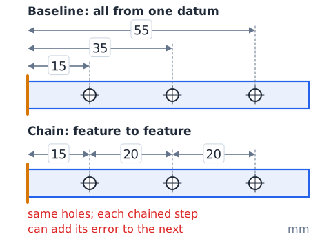
A datum is the selected reference surface, edge, plane or axis from which other dimensions are located. If each mark is measured from the previous mark rather than from one reliable datum, small errors may accumulate. For example, placing three holes 20 mm apart by repeatedly stepping a rule can introduce more cumulative error than measuring each center's location from a clean reference edge. Clamp the piece securely and confirm that the chosen edge is straight and suitable as a reference before committing permanent marks.
Units: inches, feet, millimeters and centimeters
A foot contains 12 inches; an inch is exactly 25.4 mm; and a centimeter contains 10 millimeters. Inches can appear as fractions or decimals, whereas shop metric readings commonly use mm and decimals of a mm. Always attach units to a reported number: '12' alone could mean 12 inches or 12 millimeters. Do not combine a 3/8-inch hole specification with a 3.8-mm bit because the numerals seem similar. For dimensional comparisons, convert before deciding which part is bigger.
Converting inches to millimeters
To convert inch length to millimeters, multiply by exactly 25.4. As a worked example, half an inch becomes
To reverse the calculation, divide millimeters by 25.4; 25.4 mm is one inch. The factor is an exact definition, but an actual tape measurement may have uncertainty; do not invent extra trustworthy digits merely because the conversion yields many decimals. Check that an inch-to-mm conversion grows numerically because millimeters are smaller units.
Ordinary steel rule
A steel rule is a rigid straightedge engraved with inch and/or metric graduations. It is useful for setting out short distances and checking approximate dimensions, especially where a flexible tape bends. Align the zero graduation or a known readable mark carefully with the starting datum, keep the rule parallel to the measured length, and view the tick marks without tilting the eye. A chipped or rounded rule end should not be used as an unquestioned zero; start at a sound graduation and subtract the starting reading.
Ruler fraction lines
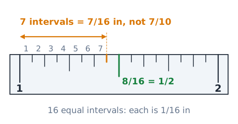
On a fractional-inch rule, longer marks usually designate major fractions and shorter marks subdivide them. If one inch is separated into sixteen equal intervals, each interval is 1/16 inch. A mark seven intervals beyond the whole-inch line reads 7/16 inch beyond that inch, not 7/10. Reducing fractions can help:
Never assume every ruler has identical subdivisions; inspect the actual scale or stated graduation before counting ticks.
Fractions to decimal inches
To convert an inch fraction to a decimal, divide its numerator by its denominator. For example,
Decimal form is convenient for comparing a nominal size with a caliper readout, but its precision is limited by the original measurement. A 3/8-inch nominal bolt should not be judged with a loose pocket ruler as though that rule directly resolves four decimal places. In exam arithmetic, reduce or convert fractions deliberately rather than comparing denominators alone.
Adding mixed fractional dimensions
Add whole inches separately from the fractional parts, then simplify. Suppose one piece measures 2 3/8 inches and another is 1 1/4 inches. Re-express 1/4 as 2/8:
For a subtraction problem, borrow a whole inch when necessary. Verify that the result is sensible by rounding each input. A layout built from accumulated measurements should still be referenced back to the original datum when accuracy matters.
Reading between marks and parallax
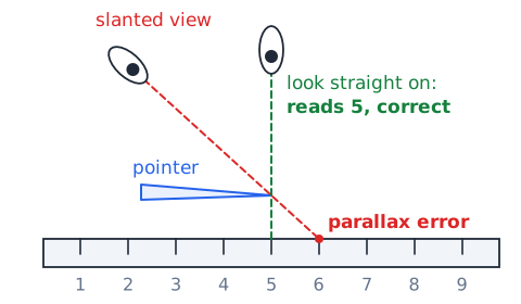
Reading an analog scale at a slanted viewing angle produces parallax: an indicator seems to line up with the wrong tick. Look perpendicular to the face of a rule or dial and use the smallest defensible increment, rather than claiming arbitrary extra digits. If a pointer lies between marks, an estimated fractional division may be appropriate depending on the instrument design. Clean lighting, correctly positioned eyes and an undamaged edge are essential. Repeating the wrong viewing angle can produce consistent but biased readings.
Tape measure parts and hook behavior
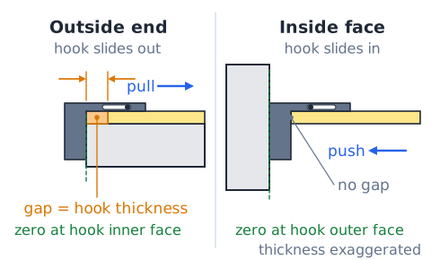
A retractable tape has a flexible graduated blade and often a sliding end hook. The controlled hook movement on a properly made tape compensates for hook thickness when pulling against an external end or pushing against an internal surface. A loose, bent or damaged hook can introduce substantial error. Keep the tape straight and under modest tension; do not read diagonally across the intended dimension. Tape measures excel at larger stock and rough layout, not small shaft diameters requiring precision instruments.
Inside versus outside tape measurement
For an outside length, the tape hook normally catches the far edge; for some inside measurements, the hook bears against an internal face. The mechanism must be sound and the manufacturer’s technique followed. Avoid substituting the case-body length unless the case actually lists and supports a known correction. Measuring the inside of a narrow slot with a flexible tape may introduce more uncertainty than using caliper inside jaws if the slot and tolerance permit. Choose a contact method that matches the geometry.
The try square
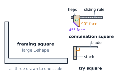
A try square has a stock and blade fixed at ninety degrees. It is used to check whether two edges are square or to transfer a perpendicular line from a reference edge across a face. Seat the stock firmly against the datum without burrs trapped underneath. A visible light gap may indicate out-of-square contact, but confirm clean surfaces and tool integrity before blaming the part. A square reports angular relationship; it does not directly prove two holes are separated by an exact linear distance.
The combination square
A common combination square includes a sliding graduated rule and a head with 90-degree and 45-degree reference faces; some versions include a level vial or scriber. Lock the head before marking, keep its reference face flush with a clean edge, and check that the ruler has not shifted. Its sliding rule can also support depth or height-related layout within the instrument’s capability. The combination square is versatile, but the sliding assembly should not be treated as a calibrated micrometer for tight fit measurements.
Framing square versus small precision square
A framing square is a large L-shaped square designed for longer woodworking or structural layouts; a small machinist's or try square is more suitable for checking a compact workpiece edge. Both represent nominal right-angle references but have different sizes, ruggedness and intended use. The correct exam choice depends on the task scale as well as the angle. A long framing square cannot make an inherently crooked board straight, and a damaged square can transfer an incorrect angle repeatedly.
Checking a square by reversal
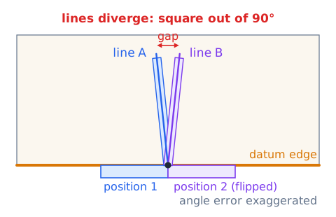
A practical comparative check is to draw a line with the square against a straight datum edge, flip the square to the opposite orientation against the same edge, and draw a second line from the same starting location. If the lines diverge, the reference edge, marking method or square may be inaccurate. Reversal reveals disagreement, but it does not replace formal verification where calibrated angular accuracy is required. Clean burrs and mark with a fine pencil or scribe to reduce line-width confusion.
Bevel gauge and protractor
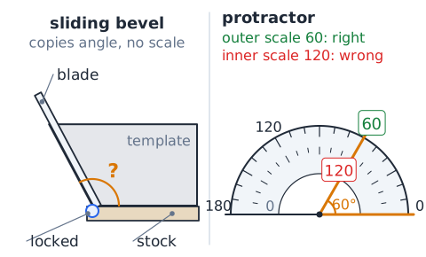
A sliding bevel gauge transfers or compares an angle after its blade is locked; it does not inherently display degrees. A protractor supplies an angular scale, often 0 to 180 degrees, for estimating or laying out angles. A combination of both may be used when a custom angle must be transferred from a drawing. Watch which baseline and direction the protractor numbers refer to: reading the wrong concentric scale can turn a 60-degree angle into a 120-degree answer.
Bubble level fundamentals
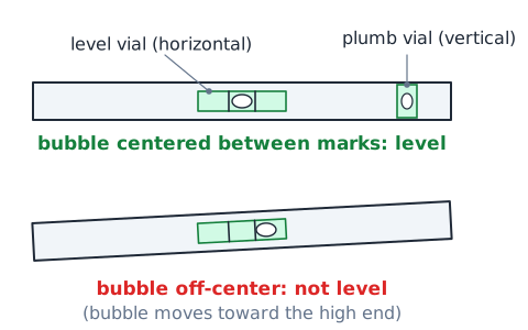
A spirit level has a vial containing liquid and an air bubble. When the vial is used as designed, centered between marks indicates its reference orientation is level or plumb, depending on the vial. Level refers to alignment with the horizontal reference; plumb refers to vertical. A level is not the same instrument as a square, which checks a right angle between two parts. Dirt under a level can give a false result, so clean both the tool and the contact surface.
Marking gauge and fence reference
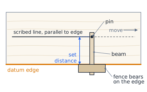
A marking gauge typically has an adjustable fence and point or wheel to scribe a line parallel to a workpiece edge. Set the distance using a rule, lock the fence, and draw it steadily along a trustworthy datum. A mortise gauge may carry two points for parallel lines with an adjustable separation. This tool transfers a spacing from the edge; it does not automatically verify the thickness of the finished cut. Ragged timber grain and a drifting fence can spoil an otherwise correct setting.
Dividers and compasses
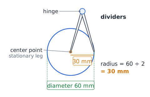
Dividers have two pointed legs and transfer a spacing or scribe circles and arcs on suitable materials. A pencil compass performs similar geometry using a pencil instead of two metal points. Keep the pivot stationary and use a secure radius setting; a loose pivot changes circle size. To construct a circle with diameter 60 mm, set the radius to half the diameter, 30 mm. Treat the pointed legs as cutting hazards and protect finished precision surfaces from unintended scratches.
Scriber, layout dye and visibility
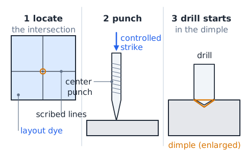
A scriber makes a narrow scratch line on metal; layout dye provides a contrasting colored background for the line. Compared with a thick pencil mark, a scribed line can make a drill center easier to locate, but it is permanent surface damage unless removed during later machining. Avoid scribing finished or safety-critical surfaces without a procedure that permits it. Clamp the part and keep the point away from hands. The scribe marks a location and cannot itself guarantee that a cut will follow the line.
Center punch and drill starting point
A center punch makes a small indentation at a selected hole location so a drill can start with less tendency to wander. Locate the intersection of layout lines, check all dimensions, then apply a controlled strike with an appropriate punch and hammer. A center punch is not a hole saw, drill bit or gauge. A punch mark that is misplaced cannot be erased by pressing harder; correct the layout before enlarging or machining the hole. Use appropriate eye protection and workpiece restraint.
Surface plate and height gauge
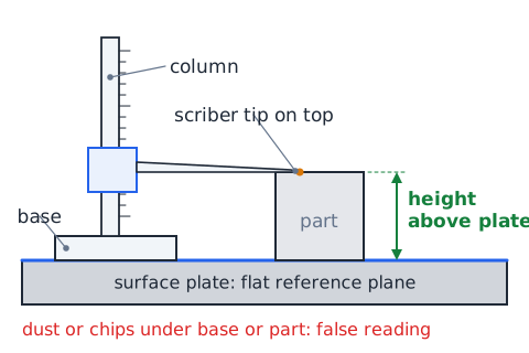
A surface plate provides a flat reference plane for comparative measurements and layout, commonly in precision shop practice. A height gauge references the plate and measures or scribes height above it. A rough wooden bench is not equivalent to a clean, verified surface plate. Dust, chips and a rocked workpiece corrupt readings. The height gauge shows height from its chosen base; when the job uses another datum, a conversion or setup is needed. Avoid overstating tenths of a millimeter from a crude setup.
Outside, inside and depth dimensions
An outside diameter spans external opposite surfaces, an inside diameter spans the interior of a hole, and depth is measured from a top datum down to a bottom feature. A caliper can have separate outside jaws, inside jaws and a depth blade or rod; each contact geometry has limitations. For an irregular part, the largest outside width may not be a true diameter. Before picking an instrument, decide whether the drawing asks for ID, OD, depth or overall length.
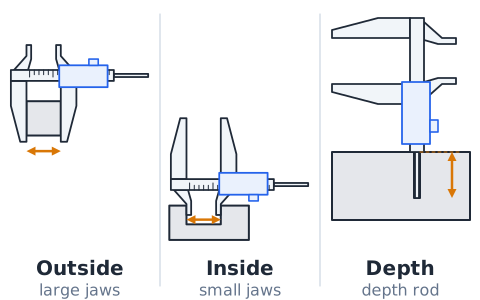
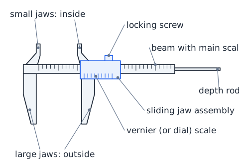
Caliper anatomy
A typical caliper has a beam, sliding jaw assembly, main scale, an indicator system (vernier, dial or digital), locking screw, and often a depth rod. Large jaws usually measure outside sizes and small upper jaws measure inside dimensions. A shoulder can make step measurements on suitable models. The caliper is more versatile than an ordinary rule but its measuring faces can be damaged by grit. Identify which surfaces actually contact the feature rather than pressing any protrusion into a hole.
Using outside caliper jaws
Clean the part and jaws, close the jaws gently to check zero, place the faces square to the external feature, and apply light repeatable contact force. If the jaws are tilted on a cylindrical shaft, the displayed width can be misleading; rock the caliper gently to find the correct diameter alignment without gouging the part. Do not squeeze soft plastic until the reading stops changing; you may be deforming it. Record units and avoid reporting accuracy greater than the instrument and setup support.
Using inside caliper jaws
The small inside jaws contact opposing interior surfaces such as a slot or bore. Open them gradually and align the measurement direction across the intended diameter, not along a chord that undershoots the widest distance. Burrs, jaw geometry and too little contact area can bias the result. For a tightly toleranced bore, an appropriate bore gauge or internal micrometer may be superior. Do not confuse the external length of the inside jaw tips with a reading of the actual opening.
Caliper depth rod
The depth rod extends from the end of many calipers as the slider moves. Rest the caliper base on the top reference surface, keep the beam perpendicular, and let the rod touch the bottom without excessive pressure. A recessed bottom with chips may cause a shallow reading, and a broad rod tip cannot always reach a tiny hole bottom. In a depth question, visualize the top reference surface before reading; an angled caliper can overstate depth relative to the true perpendicular distance.
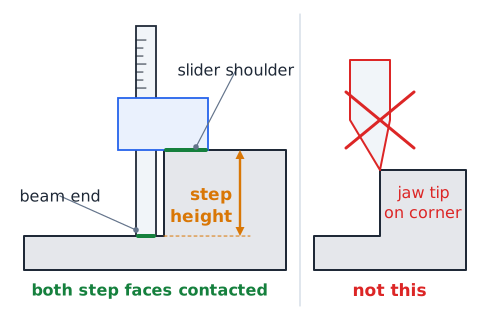
Step measurements
Some calipers can measure a step by using their opposed rear shoulders rather than the main jaws. Proper contact references both step faces. It is not sufficient simply to rest an outside jaw against a sharp corner and infer the step from the visible gap. Check the instrument's manufacturer instructions because step-measuring features differ by design. A square, a depth gauge and a caliper are alternative choices depending on the target feature and expected tolerance.
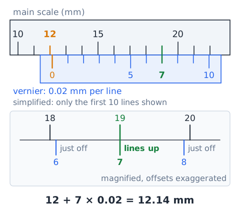
Vernier scale concept
A vernier caliper has a main scale and a short auxiliary scale whose divisions are spaced to create alignments at fine increments. Read the main-scale value just before the vernier zero, then find the matching vernier line and add its indicated increment. The incremental value depends on that particular instrument’s markings; never assume all verniers use 0.02 mm or 0.001 inch. The visual overlap is a reading method, not proof the jaws are correctly aligned with the part.
Worked vernier reading
Suppose a hypothetical metric vernier has 0.02-mm graduations. Its zero lies just after 12 mm on the main scale, and the vernier's seventh division aligns. The reading is
The 0.02-mm number is specified for this example, not a universal property. If the vernier zero lies between whole-millimeter marks, reading 13.14 mm would incorrectly add a full millimeter. Check zero offset and jaw seating separately from the scale arithmetic.
Dial caliper fundamentals
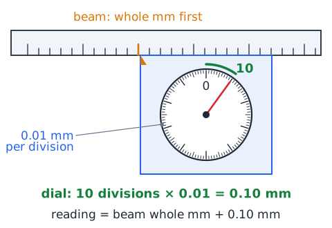
A dial caliper combines beam graduations with a circular needle that represents a smaller increment, usually stated on the instrument face. Read the whole beam units first, then add the dial’s indicated contribution. If a dial indicates 0.01 mm per division, ten divisions represent 0.10 mm; another design may have a different scale. A dial's apparent zero is not sufficient if the closed jaws do not return to zero repeatably. Inspect the scale legend before calculating.
Digital caliper fundamentals
A digital caliper displays a numerical value and often allows switching between inch and millimeter modes. Confirm the unit icon, clean and close the jaws, and verify the zero before measuring. Pressing zero at an arbitrary jaw opening can produce relative differences rather than absolute dimensions; know which measurement mode is active. A display showing 12.345 mm is not automatically accurate to 0.001 mm. Resolution is the displayed increment, while accuracy requires calibration and a controlled technique.
Zero error and correction
A zero error occurs when an instrument indicates a nonzero reading at its intended zero condition. If a caliper reads +0.04 mm with clean closed jaws, an uncorrected 10.40-mm display would imply a 10.36-mm dimension under a simple additive-offset model:
Do not assume all errors are constant offsets; damaged jaws, contamination, cosine misalignment and temperature can make a simple correction invalid. Follow the instrument's verification procedure before using corrected values for acceptance decisions.
Micrometer purpose and construction
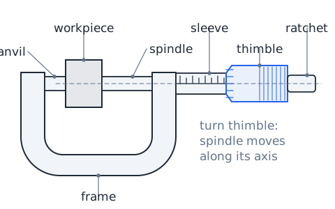
An outside micrometer typically has a frame, fixed anvil, moving spindle, sleeve scale and rotating thimble, often with a ratchet or friction thimble for repeatable measuring force. It is optimized for certain outside measurements where precision matters. A standard 0-to-25-mm outside micrometer does not measure an internal hole diameter without specialized attachments. Be careful not to confuse the thimble rotation with direct linear distance; the internal screw converts rotation to spindle travel according to its pitch.
Using a micrometer correctly
Clean both anvil and spindle, check the instrument's zero or reference standard, place the work perpendicular to the spindle axis, and use the ratchet or specified force mechanism gently. Tightening the thimble forcefully can distort soft work or the tool. Allow a temperature-stabilized workpiece when a tight tolerance matters; a hot part can expand. Avoid measuring over a chip or burr. The ratchet improves force consistency, but it does not eliminate tool wear or the need for calibration.
Reading a metric micrometer
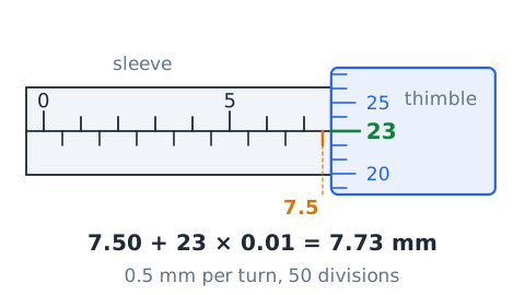
A common metric micrometer advances its spindle 0.5 mm per revolution and has 50 thimble divisions, giving 0.01 mm per division. If the sleeve shows 7.5 mm and thimble mark 23 is aligned, then
This is a worked example for that pitch/division combination; check the actual model before copying the method. Do not miss the half-millimeter line on the sleeve, a frequent source of exactly 0.50 mm error.
Micrometer pitch is instrument-specific
The spindle’s screw pitch determines travel per full revolution:
where p is distance per turn and N the number of turns. If a hypothetical micrometer moves 0.5 mm per turn, three turns produce 1.5 mm of travel. One should not infer the pitch from another manufacturer’s markings. A micrometer can be highly repeatable and still systematically wrong if its anvil is dirty. In the exam, use given pitch and graduation data rather than memory when a reading diagram specifies its divisions.
Telescoping and bore gauges
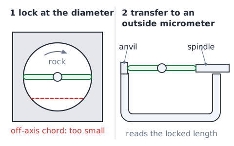
Telescoping gauges transfer an internal bore dimension to an outside micrometer; dial bore gauges compare internal diameter against a pre-set reference. They are not just oversized caliper jaws. They demand correct alignment and careful rocking to locate a diameter rather than an off-axis chord. A go/no-go plug gauge, by contrast, quickly checks whether a hole falls within specified limits and may provide no continuous numeric dimension. Match the question's verb: measure, transfer or accept/reject.
Feelers and gap measurements
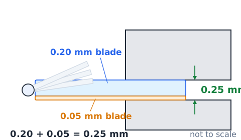
A feeler gauge uses thin blades of known thickness to test narrow gaps, such as a specified clearance. Choose a clean, undamaged blade or a documented combination, insert it without excessive force, and interpret drag according to the relevant procedure. Adding a 0.20-mm and 0.05-mm blade nominally gives 0.25 mm; dirt between blades alters the result. A feeler gauge measures a gap, not a hole diameter or a shaft's roundness. Treat printed sizes as nominal and use a verified gauge for critical work.
Thread pitch gauge
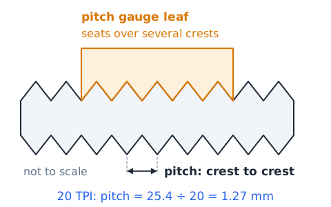
A thread pitch gauge has shaped leaves that match a screw's thread spacing. For metric threads, pitch is usually distance between adjacent crests in millimeters; in inch series, threads per inch (TPI) is common. A leaf that seats over several crests can help identify pitch, but it does not prove that the fastener has the correct diameter or that the thread form is undamaged. Do not mix pitch and TPI: a 20-TPI thread has pitch
not 20 mm.
Wire gauge and drill-size references
Numbered drill sizes and wire gauges use systems in which the printed number is not directly the diameter in inches or millimeters. Consult the applicable size chart; a 'No. 10' label cannot be assumed to mean 10 mm. Drill bits can be checked with a drill index, while a gauge plate has holes or slots of designated sizes. A gauge that identifies an approximate nominal size differs from a calibrated micrometer reporting a measured dimension. Read the scale specification before making numeric comparisons.
Dial indicator: changes, not absolute length by default
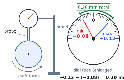
A dial indicator tracks small movement of a probe relative to a starting reference. It is commonly used to check runout, alignment variation, or flatness variation with a suitable fixture. A needle that swings 0.20 mm peak-to-peak has recorded a total indicated variation of 0.20 mm; that number is not automatically the shaft's outside diameter. With a round rotating part, the interpretation as runout depends on setup and alignment. Secure the indicator stand so the base does not wander during the test.
Total indicated runout basics
Suppose a dial indicator reads a minimum of -0.08 mm and maximum +0.12 mm during one turn in a particular setup. The total indicated variation is
This peak-to-peak value does not tell you which component caused the variation without a controlled reference. Keep probe contact consistent, rotate slowly where safe and follow the inspection procedure. Misinterpreting the negative value as an extra error to subtract twice produces the wrong arithmetic.
Gauge blocks and standards
Gauge blocks are precision length artifacts used to establish or verify dimensions in appropriate metrology settings. They help compare an instrument with a known length; they are not general-purpose clamps or scraping blocks. Handling temperature, cleanliness, surface damage and traceability matter. A precise-looking block that lacks trustworthy verification may not support a high-stakes acceptance decision. For ASVAB-level recognition, remember the functional relationship: reference standard supports checking a measuring instrument, while the caliper or micrometer measures the workpiece.
Accuracy, precision and resolution
Accuracy concerns closeness to an accepted reference; precision concerns repeatability or agreement among repeated readings; resolution concerns the smallest displayed increment. A digital device repeatedly displaying 10.25 mm can be precise but inaccurate if a known 10.00-mm standard actually reads 10.25 mm. Five decimal digits on a display do not create calibration. Questions may deliberately swap these terms; ask whether the stem describes closeness to the reference, consistency of repeated readings, or display spacing.
Tolerance and nominal dimension
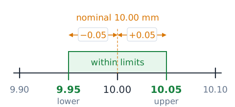
A nominal dimension is the named target size; a tolerance states permitted variation. If a pin is specified as , dimensions from 9.95 through 10.05 mm are within those stated inclusive limits. This is a drawing interpretation example, not a standard fit for any real part. A measuring instrument should be capable of making a meaningful decision relative to that band. Always inspect whether limits are symmetric or separately specified above and below nominal.
Calculating upper and lower limits
For a 25.00-mm target with +0.10/-0.05-mm deviations, upper limit is
and lower limit is
An observed 24.94 mm is below the allowed band, assuming adequate measurement assurance. The tolerance describes acceptable part variation, not the accuracy of the measurement instrument. Keep plus and minus directions tied to the dimension rather than assuming all drawings use a symmetric plus/minus tolerance. If a reading lands exactly on one boundary, this simplified example includes it; real inspection decisions also consider measurement uncertainty and a documented acceptance rule.
Clearance and interference
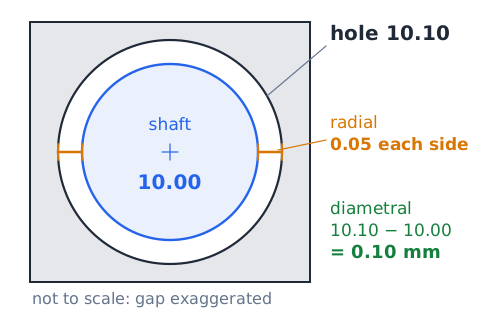
Clearance describes positive space between mating features. A simple nominal clearance calculation is
A 10.10-mm hole and 10.00-mm shaft give 0.10 mm diametral clearance, while a hole smaller than the shaft yields a negative mathematical difference and suggests interference. The result is not automatically the radial clearance: when centered, radial clearance is half the diametral clearance. A real fit analysis also needs tolerances, shape and operating conditions.
Absolute error and percent error
For an educational comparison against a reference of 50.00 mm, a measurement of 49.50 mm has an absolute error magnitude of 0.50 mm. Relative percent error is
This illustrates arithmetic, not a substitute for the more rigorous uncertainty analysis used in calibration. Do not divide by the indicated value when the problem asks for error relative to the accepted reference. A percent error has no dimensional unit.
Repeated readings and averaging
Taking several measurements can reveal scatter and occasional gross mistakes. For readings 10.0, 10.1 and 9.9 mm, the mean is
The average does not eliminate systematic bias; if every reading is shifted by a damaged zero, the mean is biased too. Record conditions and compare the spread with the required tolerance. Averaging should not be used to conceal a part that varies significantly across different locations when that shape variation matters.
Temperature, expansion and handling
Metal dimensions change with temperature, and warm hands can influence small, highly precise parts or tools. In ordinary hand-tool tasks the effect may be minor, but it matters as tolerance requirements tighten. Allow the part and instrument to stabilize at an appropriate shop reference temperature when the procedure demands it. Do not grip a micrometer frame excessively or leave a precision gauge on a hot machine. Recognize that a perfect scale reading taken on a heated component might not represent its intended inspection condition.
Cleanliness, burrs and measuring pressure
Chips and burrs trap a measuring face away from the true surface. Wipe the part and contact faces, avoid abrasive cleaning that changes dimensions, and use consistent gentle pressure. Soft stock can compress under caliper jaws or a micrometer spindle. Different operators may obtain different values if each squeezes differently. When a reading is surprising, first inspect contact conditions, instrument zero, units and alignment before concluding the manufacturing process made a bad part.
Parallelism, perpendicularity and squareness
Parallel surfaces remain the same distance apart ideally; perpendicular surfaces meet at 90 degrees. A square may check local angular relationship and an indicator may reveal variation, but one reading at one location cannot prove global geometry. To lay out a line parallel to a board edge, a marking gauge is generally more direct than a try square. To lay out a perpendicular line, seat the square's stock against the datum edge. Distinguish the geometry word from the measurement magnitude before choosing an instrument.
Laying out hole centers from an edge
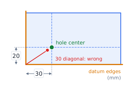
A simple shop layout often specifies a hole-center offset from a left edge and from a bottom edge. Start from verified square datum edges, measure each coordinate, and scribe light crossing lines. Then check dimensions before center-punching at the intersection. For example, a center specified 30 mm from the left and 20 mm from the bottom must satisfy both coordinates independently. Measuring 30 mm diagonally from the corner does not establish the required horizontal offset.
Layout from a baseline versus chaining
Baseline dimensioning locates multiple features from one datum; chain dimensioning specifies distances sequentially from feature to feature. Both may appear on a drawing, but careless manual chaining can accumulate setup errors. For three hole centers at 15, 35 and 55 mm from an edge, make marks from the same verified zero whenever the drawing calls for baseline positions. If a print uses chain dimensions, sum the segments correctly and cross-check the total against an overall dimension if provided.
Scale drawings and scale ratios
A scale drawing reduces or enlarges represented dimensions by a defined factor. At a drawing scale 1:2, a 50-mm line on paper represents 100 mm on the actual workpiece if the drawing is printed at true size. Never measure a screen screenshot and treat the pixel length as real without a reliable scale. Written dimensions on an engineering drawing take priority over casual ruler measurements of a displayed image. The ASVAB may test proportional reasoning; write the ratio direction explicitly before multiplying.
Pythagorean check for a right angle
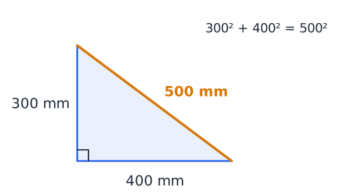
A 3-4-5 triangle is a familiar way to check a right angle in layout. If two perpendicular legs are 300 mm and 400 mm, the diagonal should be
Scaled multiples such as 6-8-10 also work. This method assumes straight reference edges and properly located endpoints. Measuring a diagonal alone does not prove that both sides have the required lengths; use all three measurements. A square is usually quicker for small stock, while diagonal checks help on larger frames.
Circumference and diameter in round layouts
A circle's circumference is
where d is diameter and r is radius. For a 40-mm diameter circle, circumference is approximately 125.66 mm. A compass is set to radius 20 mm, not diameter 40 mm. Marking circumference with a tape around a round object can be practical for rough sizing, but calculated diameter depends on accurate circumference and circular shape. Do not confuse curved surface distance with a straight outside caliper reading across the diameter.
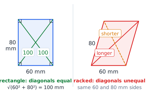
Checking diagonal equality in a rectangle
A rectangle with width 60 mm and height 80 mm has diagonal
Opposite diagonals should agree in a properly rectangular layout with correct side lengths, but equal diagonals alone do not prove every corner is square without additional conditions. Cross-check the side dimensions and the chosen reference edges. For a small box, use a suitable square; for a larger layout, diagonal comparisons can expose racking. Avoid rounding intermediate squares carelessly in exam calculations.
Choosing the instrument by tolerance
A tool's measuring capability should be sufficient relative to the allowable variation. A tape with millimeter marks is inappropriate for accepting a shaft tolerance of ±0.01 mm; a verified micrometer may be appropriate. Likewise, using an expensive micrometer to rough-mark a six-foot board may slow work without improving the needed result. Do not equate finer resolution with guaranteed accuracy. Choose based on dimension type, required tolerance, range, access, material and safe application.
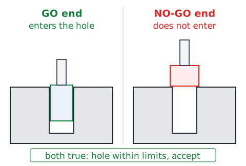
Go/no-go logic
A go/no-go gauge uses two functional limits rather than returning a detailed numeric size. Under the appropriate gauge plan, one end should enter or fit and the other should not. The meanings of GO and NO-GO depend on whether the gauge checks a hole or shaft and on the specific gauge design, so follow the stated inspection setup. A go/no-go result can efficiently establish conformity within a tolerance range without telling you the exact diameter. Do not describe it as a caliper substitute when numeric data are needed.
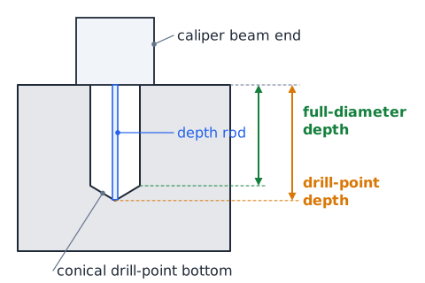
Measuring a blind recess
A blind hole ends inside material rather than passing all the way through. A depth gauge or caliper depth rod may help find the depth if the bottom is reachable. A caliper's inside jaws measure an opening width, not the depth to the blind bottom. Chips or a conical drill-point bottom can change what 'depth' means; some drawings distinguish full-diameter depth from total drill-point depth. Identify the correct reference plane and contact surface before reading.
Step-by-step layout of a simple bracket
Consider a rectangular bracket requiring two holes at equal heights and different offsets from one end. Confirm the drawing units and required datum edges; clean and clamp the bracket; mark the common height using a square or height gauge; measure each longitudinal center position from the datum; then inspect the intersection marks. Only after rechecking do you center-punch. Measure both finished hole spacing and edge distances after drilling if the job calls for inspection. This systematic sequence reduces costly errors from premature irreversible marks.
Common exam trap: inside jaws versus outside jaws
When a question asks for a hole's diameter, select inside measuring contacts or an appropriate bore gauge, not the outside jaw faces merely because the caliper is named. Conversely, measuring a shaft diameter requires outside jaws or an outside micrometer. Some drawings describe diameter using the symbol Ø, while distance between straight sides may be labeled width. Select the contact surfaces first and the scale-reading method second. Very small holes may exceed the practical capability of ordinary caliper inside tips.
Common exam trap: accuracy versus detail
A digital display reading to 0.01 mm is not proof that a dusty, uncalibrated caliper can inspect a ±0.01-mm tolerance. The instrument's published accuracy, wear, zero, repeatability and setup all matter. A measurement can be repeatable yet wrong and a coarse rule can still be adequate for a rough lumber cut. On multiple-choice questions, reject answers that promote a tool based only on its number of screen digits without considering contact geometry and required tolerance.
Common exam trap: metric versus customary
A 1/4-inch dimension is 6.35 mm, not 0.25 mm. A 12-mm socket will not fit a 1/2-inch hex despite numerical proximity because a half inch is 12.7 mm, larger than the socket opening. When a question mixes unit families, convert explicitly using
before selecting an option. Watch for decimal punctuation, omitted unit symbols, and deceptive 'same number' assumptions. Tool markings must correspond to the actual specification.
Common exam trap: the line versus the finished part
A scriber makes a layout mark, but cutting, sawing or drilling introduces tool width and material removal. A thick pencil line has a width, and choosing its wrong edge can shift the finished part. When accuracy matters, the work instruction must define the reference side of a line or use center marks and proper machining offsets. A square checks a marked line's direction; it does not prevent a drill from wandering or guarantee finished-hole tolerance.
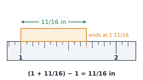
Worked problem: fractional ruler reading
A ruled scale has sixteen equal ticks per inch. A workpiece begins exactly at the 1-inch line and ends at the 1-and-11/16-inch line. The measured length is
not 1 11/16 inches. If the left endpoint is not at zero, subtract its coordinate from the right endpoint. A frequent distractor reports the endpoint reading itself as the workpiece's length. Look for two endpoints before doing the subtraction.
Worked problem: offset reading on a steel rule
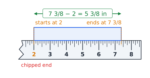
The first usable mark on a damaged rule is the 2-inch line. A part begins there and ends at 7 3/8 inches. Its length is
The arithmetic is valid only if the graduations remain accurate and aligned. Starting at a nonzero mark is a practical workaround for a chipped zero end, but it does not repair a bent or stretched measuring instrument. Read and subtract both positions rather than blindly trusting the rule end.
Worked problem: caliper and specification
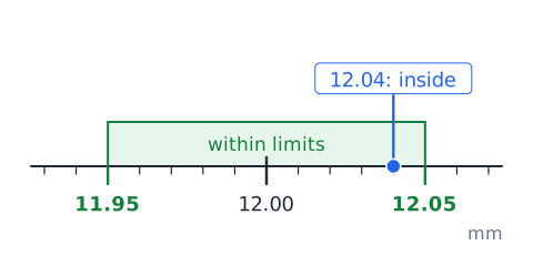
A sample shaft reads 12.04 mm on a properly checked instrument. The drawing specifies 12.00 ± 0.05 mm. The allowable range is 11.95–12.05 mm, so 12.04 is inside the stated interval, assuming adequate measurement assurance. The answer changes if the instrument is known to have a +0.10-mm systematic error. A multiple-choice item may test either tolerance arithmetic or quality of the measurement setup; read every condition rather than automatically accepting a number within limits.
Worked problem: hole and shaft clearance
A nominal bore is 15.20 mm and a nominal shaft is 15.05 mm. Diametral clearance is
If both parts are perfectly concentric and circular, nominal radial clearance is 0.075 mm. Real tolerance ranges could allow a smaller or larger gap, so do not present the nominal difference as a worst-case guarantee. The sign tells you whether the simple arithmetic indicates clearance or potential interference.
Worked problem: a symmetric hole layout
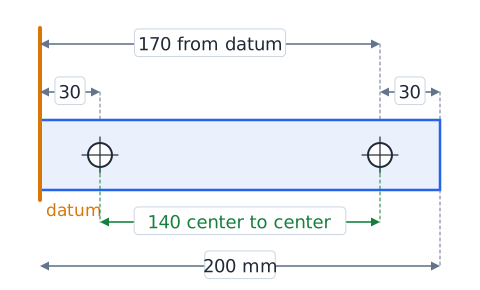
A 200-mm-wide plate requires two holes with centers 30 mm from their nearest side edges. From the left datum, the first center is at 30 mm and the second is at
Center-to-center spacing is
Confusing edge-to-center distances with center-to-center spacing yields 170 mm, a frequent distractor. Draw a quick one-dimensional baseline and check the distances sum to the full 200 mm.
Worked problem: metric tolerance subtraction
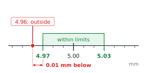
A measured groove width of 4.96 mm is compared with an allowable band of 5.00 ± 0.03 mm. Its lower boundary is 4.97 mm, so 4.96 mm is 0.01 mm below the specified range. This determination assumes a trustworthy instrument and a measurement uncertainty that is small relative to that difference. A go/no-go gauge or an accurate measuring instrument can be used under the proper procedure; a ruler divided in millimeters is unsuitable for resolving this decision.
Worked problem: measuring a drill pattern
Hole centers on a drawing are 1.25 inches, 2.50 inches and 3.75 inches from the same edge. The equal spacing between successive holes is 1.25 inches. The span from first to third is
not 3.75 inches. Dimension strings should be interpreted as coordinates when they share one datum, rather than added as if each were a chained offset. Lay out from the same edge to reduce cumulative marking errors.
Reading strategy for Shop Information
First decide what property is needed: length, width, depth, diameter, angle, alignment or acceptance within tolerance. Next identify the tool geometry: rule, square, protractor, caliper, micrometer, gauge or indicator. Finally perform arithmetic only if the stem supplies graduations or dimensions. On computer-adaptive testing, respond to the item presented without assuming you can skip backward or change it later; follow the actual administration’s on-screen instructions. Avoid memorizing imagined official question wording; master the relationships between tools and tasks.
Exam scenario: damaged instrument
A shop rule has a chipped zero end, a caliper will not return to zero, and a square has a visible bent blade. Their defects are not equivalent. A sound interior rule graduation might be usable after subtracting readings for rough measurement; a caliper with unexplained zero drift should be checked and corrected before use; a bent square must not be trusted to lay out a right angle. OSHA's general safe-tool principle applies independently of any calculation: do not use defective equipment in a way that could be unsafe.
Exam scenario: blind hole and thread pitch
A blind tapped hole has a nominal opening diameter, an internal depth and a thread pitch. These are three different properties. A caliper may estimate opening size when its tips fit; a depth rod may locate a reachable bottom; and a matching thread pitch gauge may help identify pitch at an accessible thread, though it does not measure blind-hole depth. If a question asks for pitch, do not choose the depth gauge because the word 'hole' appears. Match the property to the mechanism.
Exam scenario: repeated readings differ
Three readings on a soft rubber spacer differ because the operator squeezes the caliper with changing force. The main issue is inconsistent contact and material deformation, not a failure to convert inches. Use a procedure that controls force and suits the soft workpiece. Check cleanliness and zero, then repeat with a consistent method. If measurements remain scattered beyond the decision tolerance, report the uncertainty instead of choosing whichever number makes the part pass. Good shop practice avoids arbitrary selection of favorable readings.
Exam scenario: choose an angle tool
A worker must transfer an existing odd angle from a template onto a board without knowing the angle in degrees. A sliding bevel gauge can capture and transfer the angle after being locked. If the question instead requires setting a known 37-degree angle from numerical instructions, an appropriate protractor or angle gauge is needed. A try square by itself sets 90 degrees and a combination square commonly provides 45 and 90 degrees. Similar tool shapes do not override their intended functions.
Final shop checklist
Read the requirement and unit; choose a sound datum; select a tool with suitable geometry, range and capability; clean contacts; zero or verify the scale; hold the tool squarely using gentle repeatable force; avoid parallax; record the correct units; compare with tolerance; and recheck an unexpected result before marking or machining. For layout, check positions from their specified references before a permanent center-punch mark. For an exam, eliminate tools that measure a different property, even if their names sound familiar. Accuracy begins before you read the scale.
 English ▾