 ASVAB Camp
Lesson mission and exam expectations
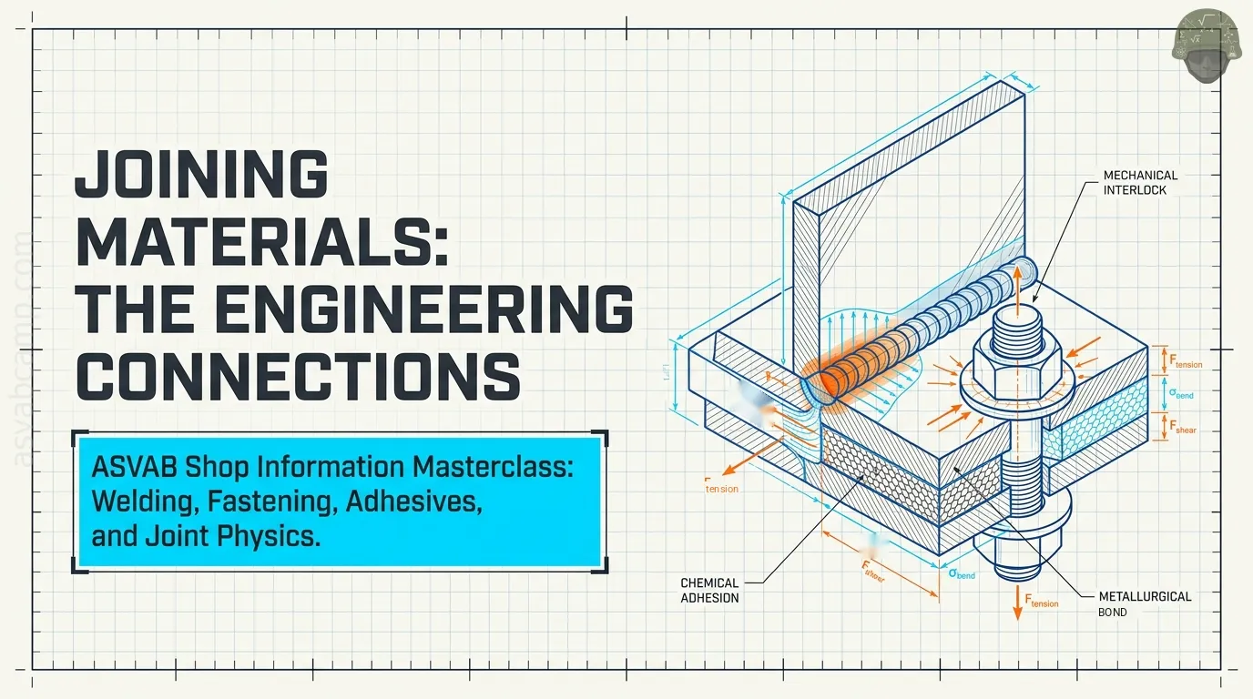
This Shop Information lesson introduces choices for joining materials: welding, brazing, soldering, adhesive bonding, bolts, screws, rivets and specialized joints. ASVAB questions may describe a shop situation and ask which process or tool fits. Recognize what is melted, how load transfers, whether disassembly is possible and what hazards accompany the operation. The examples are original educational material, not secure ASVAB questions or instructions to perform hazardous work without training.
Four basic ways to make a joint
A joint holds separate pieces together by mechanical interlocking, metallurgical bonding, chemical adhesion or a combination. A bolt and nut clamp pieces; a rivet is deformed to retain them; a weld creates a material union; a cured adhesive distributes force through a bonded surface. Each can work well when selected for the specified materials and loads. No technique is universally strongest, cheapest, safest or easiest to remove.
Permanent versus removable connections
A removable joint can normally be taken apart without destroying its main members: an accessible bolted assembly is the classic example. Most welds, cured structural adhesives and set rivets require cutting, drilling or other damage-producing steps to separate. A joint's service requirements matter: a machine guard requiring periodic access may call for fasteners, while sealed fabricated pipework may require a qualified permanent process. Removable does not mean it will never loosen.
What is a fusion weld?
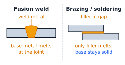
In common fusion welding, the contacting base material melts locally and solidifies into a continuous joint; filler metal may or may not be added. The heat source may be an electric arc or a suitable gas flame. This differs from ordinary brazing and soldering, where the base pieces remain solid and a lower-melting filler joins them. Remember the distinction when the question asks what actually melts.
Not all welding requires melting
The broad family of welding also includes solid-state processes such as friction welding: heat and pressure allow a bond while bulk base metal need not melt. Therefore 'welding always melts both workpieces' is too broad, even though base-metal melting characterizes typical fusion welding. For introductory ASVAB questions, look for whether the item names an ordinary arc weld, resistance weld or a solid-state process.
Basic arc-welding circuit
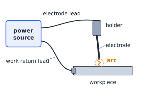
An arc welding power source supplies electrical energy through conductors and the electrode/work arrangement; an arc generates concentrated heat near the joint. Depending on the process, the electrode can itself provide filler or it can be nonconsumable. The work return lead is part of the circuit and is not a substitute for equipment protective grounding. Arc light, electric shock, heat, fumes and fire are serious hazards requiring qualified shop procedures.
Stick welding (SMAW)
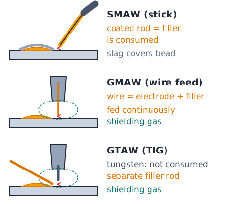
Shielded metal arc welding uses a consumable coated electrode that provides filler; the coating creates shielding products and slag that help protect the hot weld. It is distinct from processes that continuously feed bare wire with external shielding gas. The deposited weld may require slag removal and examination. In identification questions, terms such as coated rod, electrode holder and slag strongly suggest stick welding.
Wire-feed arc welding (GMAW)
Gas metal arc welding, often called MIG in basic shop language, generally feeds a continuous consumable wire electrode while a shielding gas protects the weld region. The wire serves as an electrode and filler. Unlike stick welding, there is no long coated rod changed as it is consumed. Shielding-gas suitability and work conditions influence process selection; a familiar name alone does not guarantee every alloy can be welded this way.
Tungsten arc welding (GTAW)
Gas tungsten arc welding, often called TIG, uses a nonconsumable tungsten electrode and shielding gas; separate filler may be added when required. The arc is not created by a wire that continually becomes weld metal. TIG is valued for controlled work but requires suitable skill, equipment and procedures. Distinguish the electrode's role from the filler rod's role when comparing TIG with wire-feed processes.
Resistance spot welding
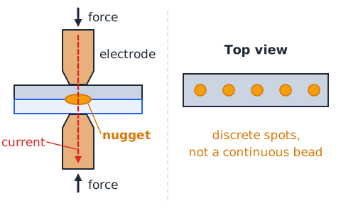
Resistance spot welding joins overlapping conductive sheets by pressing electrodes onto the stack and passing current through a localized contact region. Electrical resistance creates heating at the joint, and pressure assists the bond. It is common in sheet-metal production. Unlike a long fillet weld bead, the joint is formed at discrete spots. Proper electrode force, current and time depend on material and thickness.
Oxy-fuel welding versus cutting
A fuel-gas flame can provide heat to weld or braze certain metals; oxy-fuel cutting relies on a different reaction and oxygen jet to sever suitable material. A torch is not a single-purpose tool: the tip, gases and procedure determine the operation. A bright flame alone does not tell you whether a worker is welding, brazing or cutting. Oxygen systems present fire and pressure hazards that demand specialized handling.
Shielding and contamination
Molten weld metal can react with oxygen, nitrogen and other contaminants, producing weak or defective joints. Process shielding may come from flux coating, gases or other protective media. Paint, oil, moisture and rust can also impair weld quality or introduce hazardous emissions. Surface preparation and suitable shielding matter; simply increasing heat does not reliably correct contamination-related porosity or inclusions.
Joint forms: butt, lap and T
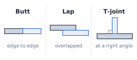
A butt joint places pieces edge to edge, a lap joint overlaps them, and a T-joint joins one part approximately at right angles to another. Corner and edge joints are other recognizable forms. The term describes geometry, not the joining method: a lap joint can be welded, riveted or adhesive-bonded. First picture the part arrangement, then identify the specific tool or bond in an exam question.
Fillet weld and groove weld
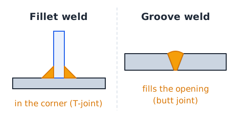
A fillet weld commonly occupies the intersection of surfaces meeting at an angle, often in a T-joint or lap configuration. A groove weld fills a prepared opening between members, often in a butt joint. The triangular cross-section used to illustrate a fillet is only a schematic. Real weld sizing, throat and acceptance are engineering tasks, not something to guess from one picture.
Tack welds and alignment
A tack weld is a small temporary positioning weld used to hold pieces during fit-up before the intended weld sequence. It does not automatically substitute for the specified final joint. Clamps, alignment checks and gap control matter because heat can distort thin metal. A few neat tack welds may make assembly easier, but they do not prove the completed structure meets its design or inspection requirements.
Heat-affected zone and distortion
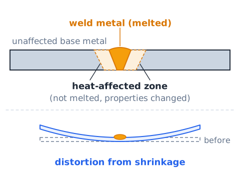
Adjacent base metal may get hot enough to change its properties without melting. This heat-affected zone is not the molten weld pool. Local heating and shrinkage can bow or twist workpieces, especially thin material. Distortion can be reduced by qualified procedure design and fixturing, but not by assuming all heat disappears harmlessly. The ASVAB-level takeaway is that welding alters both the join region and nearby material.
Common visible weld problems
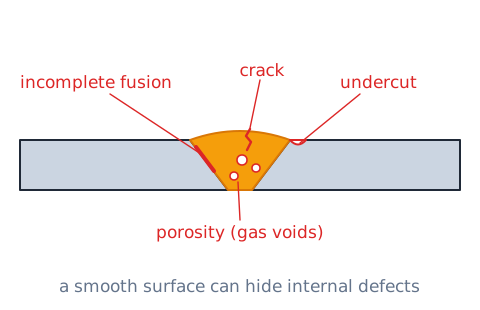
Porosity refers to trapped gas voids, undercut to a groove along a weld toe, and incomplete fusion to regions that did not bond adequately. Cracking is another serious discontinuity. Visual inspection can flag some surface indications; hidden defects may require additional appropriate inspection. A smooth-looking bead is not proof of a strong joint. Avoid diagnosing exact root causes without sufficient material and process information.
Why brazing is different
Brazing heats solid base members and melts a suitable filler metal, which flows through a joint—often with capillary action—without melting the base members. In standard U.S. process terminology, brazing filler has a liquidus above 840 °F (450 °C) yet below the melting point of the base materials. Brazing can be useful for certain dissimilar metals or thin parts. The temperature criterion refers to filler, not to a universal torch setting.
Capillary action in brazing
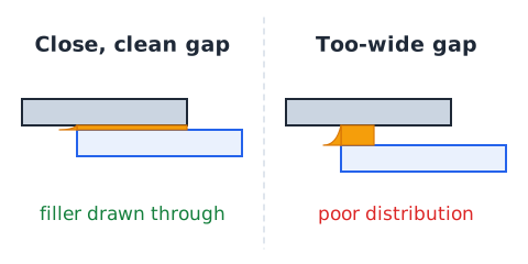
Capillary action helps molten filler enter a suitably close, clean gap by wetting the base surfaces. A gap that is too wide or contaminated may prevent effective distribution; a gap that is too tight for the process may also cause trouble. Correct clearance depends on alloy and method, not one universal value. A braze joint is not formed by simply laying a decorative glob of filler outside a poorly prepared interface.
Why soldering is different
Soldering also bonds solid base members with a lower-melting filler, traditionally with a filler liquidus at or below 840 °F (450 °C). Electronic connections are a familiar example, but solders and techniques vary. In normal soldering, the parent copper conductor or component lead is not melted. Thermal damage and flux residue can still affect reliability, so 'low temperature' does not mean that the operation is risk-free.
Flux and oxide control
Flux can help remove existing oxides and reduce further oxidation at surfaces so that molten solder or brazing filler wets the joint. Different fluxes are designed for different metals and operating temperatures. Incorrect flux, dirty metal and improper heat can cause poor bonding. Flux is not a substitute for preparation, and residues may require proper cleaning according to the material and process.
Wetting and cold solder joints
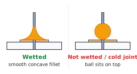
Wetting means the molten filler spreads and adheres to the correctly heated, prepared surfaces rather than sitting as a bead. A disturbed or insufficiently heated solder joint may be weak or unreliable, but appearance alone is not a complete electrical test. For electronic work, equipment qualification and manufacturer rules determine suitable inspections. The exam often contrasts a properly wetted connection with solder merely stuck on top.
Electrical soldering and conductivity
Solder mechanically holds and electrically connects conductors when a sound joint is formed. A joint should not rely only on a large blob of filler; proper conductor support and layout matter. Solder is conductive, but its resistance is not necessarily identical to copper, and a poor joint may have intermittent contact. Unlike a crimped connector, a soldered termination uses molten filler.
Crimping as a joining process
A crimp connection permanently deforms a compatible terminal around a conductor using a properly matched crimping tool. A good crimp is a mechanical connection and may also carry current; it does not require solder. The tool, terminal and conductor size must match. Simply squeezing a random connector with ordinary pliers does not establish correct retention or resistance. This is a classic recognition question for hand tools and terminations.
Mechanical fastening fundamentals
Bolts, screws, nuts, pins and rivets hold parts by a designed mechanical interface. Threads commonly generate clamping force; pins may locate parts or carry shear; a rivet is mechanically deformed to lock materials together. Selection depends on service loads, access and material compatibility. A fastener's visible size alone does not reveal its grade, proper torque or permissible load.
Bolt and nut function
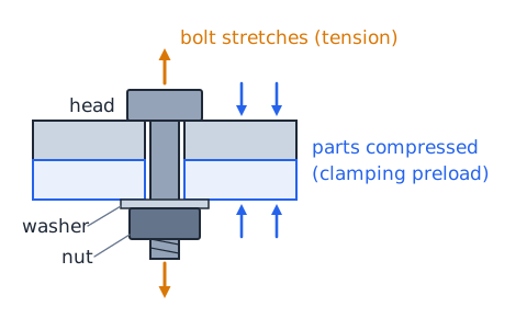
A bolt generally passes through clearance holes and engages a nut or threaded component. Turning the nut or bolt stretches the fastener slightly and compresses the clamped parts. This clamping preload is a key reason the joint resists slipping and separation. An under-tightened fastener may loosen; excessive tightening may damage threads or stretch the bolt beyond its intended range.
Machine screws versus wood screws
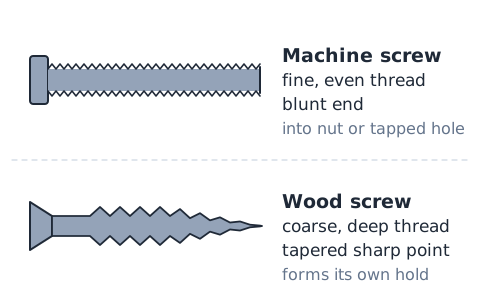
A machine screw normally engages a pre-existing mating machine thread or nut; many wood screws cut or form their own holding interface in wood. Thread form, point shape and application help distinguish them, although industry uses many specialized fasteners. Choosing by length alone is unreliable. A fine-thread machine screw forced into wood without suitable design does not become the same thing as a wood screw.
Rivets and setting
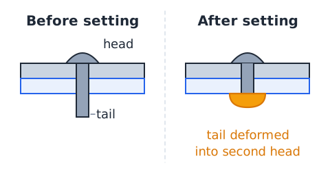
A rivet is placed through aligned holes, then its tail is expanded or otherwise deformed to form a retaining head. Blind rivets allow installation when only one side of the assembly is readily accessible. Most standard rivets are not intended for easy disassembly and often must be drilled out. Riveting joins by mechanical deformation, not by melting the joined sheets.
Pins, cotter pins and retaining rings
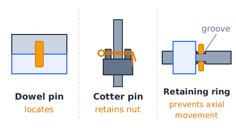
A dowel pin often aligns components, while a cotter pin can retain a castle nut or other assembly against unintended movement. Retaining rings snap into a groove to keep parts from shifting axially. These pieces are not interchangeable with structural bolts simply because they are made of metal. The ASVAB may ask whether a component locates, clamps or prevents axial escape.
Locking and vibration
Vibration can contribute to joint loosening, but no single washer or adhesive guarantees prevention in every assembly. Self-locking nuts, suitable thread-locking compounds and engineered lock features address specified conditions. A plain flat washer mainly distributes bearing pressure and provides a bearing surface; it is not necessarily a positive locking device. Always distinguish actual locking features from general hardware appearance.
Adhesives: how they work
An adhesive joins surfaces after a suitable bonding material wets the substrates and cures or solidifies. It can spread load over a wider area than a small screw or rivet. Adhesion to the surface and cohesion within the adhesive layer both matter. Joint design, exposure to heat, moisture and chemicals, surface cleanliness and cure instructions can be more important than the brand of glue alone.
Epoxy adhesives
Many epoxies are two-part systems that chemically cure after resin and hardener are mixed in specified proportions. The resulting material may offer useful structural properties, but cure time, temperature, bond preparation and material compatibility must be respected. Adding extra hardener does not automatically make the joint stronger. 'Epoxy' describes a broad family rather than one universal strength or cure schedule.
Cyanoacrylate and other glues
Cyanoacrylate adhesive often bonds small, close-fitting surfaces quickly but may be unsuitable for some impact, peel, temperature or environmental conditions. Contact cement, hot-melt adhesive and wood glue are other categories with different application methods. The exam concept is to match the adhesive to the substrate and service requirement rather than treating every glue as identical.
Surface preparation for adhesion
An adhesive works poorly when it contacts loose paint, grease, dust or an incompatible surface. Preparation may involve cleaning and approved abrasion or treatment. Some surface treatments affect special composites, polymers or coatings, so a general 'rougher is always better' rule is false. The adhesive maker's instructions govern preparation. Never sand or heat unknown coatings without assessing dust and chemical hazards.
Lap joints for adhesive bonding
A lap joint overlaps two pieces, creating an area that can carry shear across a bondline. A direct end-to-end butt joint may expose the adhesive to unfavorable stresses in some applications. More overlap can increase nominal area, but real strength may stop scaling proportionally because stress concentrates near edges. NASA adhesive joint research highlights why geometry and load path matter. Treat average stress equations as simplified study models.
Peel versus shear loading
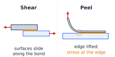
In simple shear, two bonded surfaces try to slide parallel to one another; in peel, a force lifts one edge away and concentrates stress. Many structural adhesives perform differently under these modes. A thin flexible strip peeled from a rigid plate is not equivalent to two rigid plates pulled in uniform shear. An exam question showing the direction of applied force can reveal which failure mode deserves attention.
Wood glue and woodworking joints
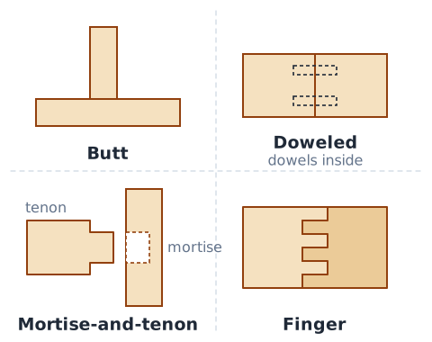
Wood glue can bond properly prepared wood surfaces; the grain direction, joint fit, moisture and clamping procedure influence performance. Butt joints, doweled joints, mortise-and-tenon joints and finger joints offer different geometry and mechanical interlocking. A clamp holds pieces in position during the specified curing interval; it does not chemically replace the adhesive. For outdoor service, confirm that the adhesive is suitable for exposure.
Mechanical plus adhesive hybrid joints
A hybrid joint may combine adhesive with bolts, rivets or another mechanical feature to achieve alignment or improve certain performance requirements. The components do not automatically split load evenly: stiffness, clearance, preload and sequence matter. A hybrid approach can also add manufacturing complexity. The useful principle is that designers sometimes combine methods; it is not a guarantee of double strength.
Material compatibility and galvanic corrosion
Joining unlike metals can create galvanic corrosion when an electrolyte and an electrical path are present. Metal selection, isolation, coatings and drainage can reduce risk. This is separate from simple thermal expansion differences, which can also stress a joint. A steel fastener in an aluminum member may require an application-specific corrosion strategy; the mere presence of dissimilar metals does not guarantee immediate damage.
Joint movement and thermal expansion
Two joined materials may expand differently as temperature changes. A large rigid joint can build stress when restrained parts have dissimilar thermal expansion. Flexible sealants, slots or properly designed joints can sometimes accommodate movement. The basic linear model uses length, expansion coefficient and temperature change; it is an approximation, not an all-purpose structural rating.
Choosing between processes
Ask five questions: what materials are being joined, what load directions act, whether disassembly is required, what temperature/environment occurs and what access/tools exist? For example, a removable motor cover often uses screws, a sheet-metal body may use spot welds, and a small electronic connection may use solder. Many alternatives remain possible; use all details in the question rather than relying on one noun.
Inspection of threaded joints
Look for missing fasteners, incorrect hardware, damaged threads, separation or evidence of movement. A torque mark can indicate relative motion in some applications, but it does not by itself prove correct preload. Follow qualified torque procedures for critical work. Replacing an unknown bolt with a similar-looking one can change material grade and joint performance.
Inspection of adhesive joints
Visible gaps, contamination or premature separation are warning signs; internal bond defects may not be visible. A joint that cured hard is not necessarily strong or compatible with its environment. Check specified bondline, preparation records, cure conditions and relevant tests. Do not assume every adhesive connection can be verified by pulling on it by hand.
Inspection of brazed or soldered joints
Look for proper wetting, continuity and joint coverage consistent with the process requirements. Excess filler piled outside a gap does not guarantee a sound internal bond. For electrical joints, appropriate continuity and functional measurements may help identify problems. Brazed pressure joints may demand formal testing beyond visual inspection. The correct test depends on use; never claim that bright, shiny metal proves safe service.
Hot-work fire prevention
Welding, cutting and related hot work can scatter sparks or transfer heat through a structure. OSHA's general-industry rules call for suitable precautions to protect combustible surroundings and may require fire watches based on conditions. Do not treat the 35-foot distance often cited in OSHA hot-work rules as an unconditional 'all work is safe past this line' rule. Permits, housekeeping and site procedures matter. Never conduct unapproved hot work on a container that may hold flammable residues.
Arc radiation and eye protection
An exposed welding arc emits intense optical radiation that can injure eyes and skin. Suitable welding helmets, filter shade, protective clothing and screens protect the operator and bystanders. Ordinary safety glasses alone do not provide the same filter protection as an appropriate welding helmet. Shade choice depends on operation and procedure; selecting the highest number without considering visibility is not a complete rule.
Fume and ventilation hazards
Welding, brazing and soldering can release fumes and gases, with hazards determined by metals, coatings, fluxes, process and airflow. Local exhaust or other engineering controls may be necessary; an open door alone does not prove exposures are safe. Never heat unknown galvanized, lead-painted or coated materials without risk assessment. OSHA identifies ventilation and hazardous fume controls as important protections.
Compressed gas handling
Oxygen and fuel-gas systems need compatible regulators, fittings and safe storage practices. Oil or grease on oxygen equipment is especially dangerous. Cylinders must be secured and inspected in accordance with the applicable rules, and only qualified workers should assemble or use torch systems. An oxygen cylinder is not simply another shop air cylinder; oxidizing conditions can greatly intensify combustion.
Electrical isolation and safe setup
Arc-welding circuits, powered fastening tools and other equipment bring shock and moving-part hazards. Inspect cables and guards, secure the work and follow prescribed isolation before maintenance. The work return cable carries welding current while protective equipment grounding serves a different safety function. Unsafe wiring should not be improvised during troubleshooting. This lesson explains concepts, not a live-equipment operating procedure.
PPE and shop housekeeping
Eye protection, appropriate clothing, shielding screens, gloves selected for the process and proper ventilation are parts of a hazard-control system. Loose clothing around rotating machinery is dangerous; gloves may be unsuitable near some rotating tools despite being useful for hot materials elsewhere. Keep floors clear and remove unnecessary combustibles. PPE supplements safe processes rather than replacing guards and ventilation.
Reading drawings and weld symbols
A drawing may identify a butt, lap or T arrangement as well as a specified joining process. Common welding symbols can convey whether a fillet or groove weld is required and where it is located. At ASVAB level, recognize geometry and the difference between a continuous line of weld and discrete spots; specialized fabrication still requires formal symbol training and approved drawings.
Basic area and load vocabulary
Force is expressed in newtons or pounds-force; area is in square millimeters or square inches; nominal stress is force divided by area. The same total force spread over a larger effective area gives a lower average stress in a simplified model. Actual welded, fastened or adhesive joints may have nonuniform stresses, and design limits must not be inferred from nominal averages alone.
Mean shear stress in a simple bonded overlap
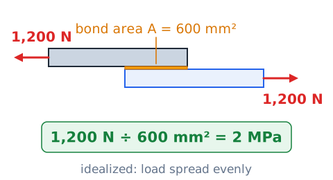
For a textbook overlap carrying a direct load of 1,200 N over a uniform effective bond area of 600 mm², the nominal average shear stress is 2 N/mm², or 2 MPa. This only illustrates force per area and assumes ideal load distribution. Adhesive strength, peel effects, material thickness and fatigue are not established by this calculation; engineers must use validated design methods.
A simple rivet shear model
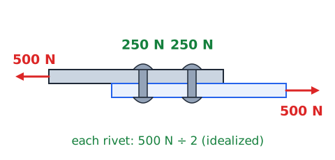
In a deliberately idealized single-shear example, a 500 N load carried equally by two identical rivets would give 250 N per rivet. This does not mean each rivet is automatically safe. Bearing stress, net-section tearing, edge distance, preload, unequal distribution and fatigue may control. The exam often tests correct load division; engineering capacity requires the actual rivet material and joint configuration.
Bolt spacing and edge distance
Fasteners near an edge may tear out the material around the hole; very close spacing can weaken the joint net section. Manufacturers and engineering standards determine appropriate spacing. Students should recognize that hole position affects strength, not merely appearance. Simply doubling bolt count in a thin strip without increasing width can reduce the remaining metal and fail to double capacity.
Simple torque and leverage
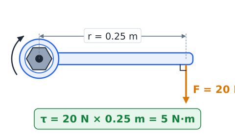
Torque is the perpendicular applied force multiplied by moment arm length. A 20 N force at a perpendicular 0.25 m wrench handle produces 5 N·m. This does not say the resulting bolt preload is 5 N or any other fixed number. Thread friction and lubrication affect tightening; manufacturer torque instructions govern actual service. Study the units and geometry, not a misleading equality between torque and force.
Threads and assembly fit
A bolt must match the mating thread's diameter and pitch; a nut should turn by hand initially when assembled correctly. Metric pitch is a distance per thread, whereas threads per inch is a count per inch. Similar-looking mismatches can damage threads. If resistance appears immediately, stop and check the parts instead of forcing the connection with a longer wrench.
Calculating simple adhesive overlap area
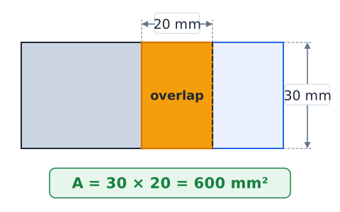
For a rectangular overlap 30 mm wide and 20 mm long, the nominal overlap area is 600 mm². This area is not automatically the true well-bonded area if voids, fillets or contamination exist. A question may ask only for area; answer that arithmetic without asserting a safe working load or warranty of strength.
Temperature conversion for process categories
The conventional soldering/brazing boundary is 450 °C, approximately 840 °F. Fahrenheit is converted using
C + 32; inserting 450 yields 842 °F, often rounded to 840 °F in process descriptions. Do not confuse filler metal's liquidus classification with the equipment thermostat setting or parent metal melting temperature. Exam items should use the stated approximation consistently.
Heat input is not an exact weld-quality score
A basic electrical energy calculation uses energy equal to power multiplied by time. For example, a nominal 1,000 W source operating 10 s delivers 10,000 J electrically. That does not mean exactly 10,000 J enters the metal or determines weld penetration; efficiencies and losses intervene. This distinction discourages converting a classroom expression directly into a procedure specification.
Joint design scenario: thin sheet
Suppose two thin steel sheets are overlapped for high-volume production. Resistance spot welding may be suitable because it produces discrete bonds under electrode force and current. A butt-edge pipe connection may require a very different qualified weld. The material, overlap, production access and quality requirements all change the selection. Never assume that 'spot weld' simply means a short arc weld.
Joint design scenario: electronics
A copper conductor meeting a circuit-pad terminal is commonly soldered with a suitable process. A compatible crimp connector is another possibility for wire termination; a high-temperature arc weld is not a routine substitute. Recognize the size, heat sensitivity and conductivity requirements. A mechanical terminal can also be electrically sound without being soldered, provided it is properly selected and installed.
Joint design scenario: serviceable bracket
A guard or access bracket that must be removed for inspection will often use a designed screw or bolt connection. Welding every connection shut can make service difficult and may introduce heat effects. This scenario emphasizes disassembly as a decisive requirement. Fastener strength and retaining features must still be selected for the load and vibration; ease of disassembly alone is not enough.
Joint design scenario: dissimilar thin metals
A brazed joint can be an option for some dissimilar thin metals because the base members ordinarily do not melt during filler flow. That does not mean every metal combination is braze-compatible. Oxide behavior, wetting, filler compatibility, thermal expansion, corrosion and service temperature must be assessed. The exam principle concerns process classification rather than promising a universal repair method.
Joint design scenario: lightweight bonded panel
For a broad, thin overlap with carefully prepared surfaces, a qualified adhesive joint may spread load across an area and avoid drilling holes. However, edges can experience peel and stress concentrations, so an overlapping rectangle is not automatically safe. If the service involves heat or chemicals, adhesive compatibility becomes important. Mechanical fastening could be preferable when quick disassembly is required.
Quick recognition: heat versus deformation
A riveter changes fastener geometry; a soldering iron melts a filler; a brazing torch heats a joint so a filler that melts above solder temperatures but below the base metal can flow; an arc welder supplies concentrated heat for welding. Adhesive bonding relies on material chemistry or solidification rather than intentionally melting metal at the workpieces. The question may describe the tool without naming the process, so identify the mechanism.
Common trap: stronger by temperature alone
Higher temperature does not automatically give a stronger joint. A properly designed solder joint can be appropriate electrically, while an unsuitable arc weld can damage heat-sensitive components. Brazing and welding are categorized by process behavior, not by one ranked ladder of strength. Base materials, filler compatibility, geometry, workmanship and conditions govern suitability.
Common trap: bigger bead equals better bond
Adding excess solder, braze filler, adhesive or weld material does not guarantee improved joint quality. Large external fillets can mask poor wetting or hidden discontinuities, and adhesive thickness has specification-dependent effects. The key is whether the intended surfaces are bonded according to the process and design. When a question asks about a defect, choose cleaning, fit or qualified process control rather than simply adding more material.
Common trap: appearance proves strength
A rivet that looks neatly headed, a bright solder joint or a smooth weld bead could still have hidden defects or unsuitable material properties. Visual inspection is valuable but limited. A better answer recognizes inspection appropriate to the intended load and use. Resist absolute words such as 'always', 'completely' and 'guaranteed' when judging a join from its surface.
ASVAB comparison checklist
First identify the materials. Next identify whether the parent metal melts, whether filler melts, and whether fastening or curing is involved. Then inspect the geometry and ask if removal, electrical conductivity or heat sensitivity matters. Eliminate answer options inconsistent with those facts. Many Shop Information questions are solved by classifying a familiar tool correctly before any calculation is needed.
Worked review: material and load
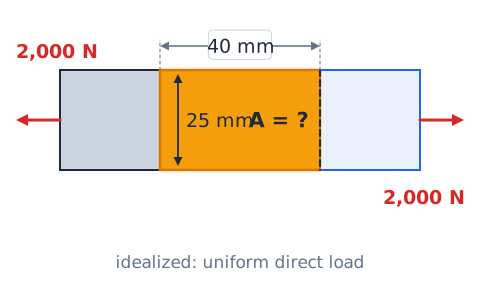
A rectangular adhesive bond 25 mm wide and 40 mm long has nominal area 1,000 mm². A simplified uniform direct load of 2,000 N corresponds to 2 N/mm² average stress. In a real eccentric lap joint, peel and edge stresses may govern. The useful test skill is multiplying dimensions and dividing force by area while explicitly stating the simplification.
Worked review: joint quantity
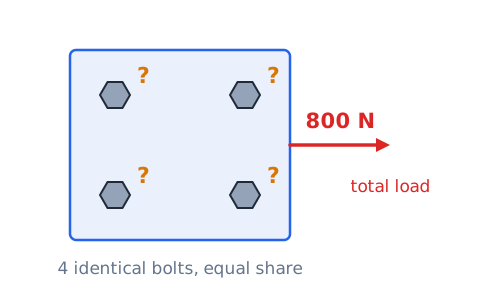
A drawing shows four nominally identical bolts sharing an idealized direct 800 N load equally. The arithmetic share is 200 N per bolt. If one bolt loosens, you cannot assume the three remaining bolts automatically receive precisely 266.7 N each under real conditions. Stiffness, fit, location and preload influence distribution. Use equal sharing only where the problem explicitly permits it.
Mini drill: identify a method
For each phrase, name the process: 'a coated rod supplies filler and slag' indicates SMAW; 'a tungsten electrode that is not consumed' indicates GTAW; 'molten low-temperature filler wets a circuit pad' indicates soldering; 'a tail is deformed into a second head' indicates riveting. Explain the clue, not just the answer. Words about heat or metal alone are not sufficiently diagnostic.
Mini drill: choose a safer response
If a work area contains nearby combustibles and lacks required hot-work controls, the appropriate response is to stop and establish approved fire precautions before welding. If a conductor's insulation melts under soldering heat, correct process controls rather than continuing unchanged. If an adhesive's specified cure has not completed, avoid loading it as if at full rated condition. Safety and workmanship are joined decisions.
Summary: the five key contrasts
Fusion welding ordinarily melts base material; brazing and soldering melt a compatible filler while the base remains solid; adhesives bond prepared surfaces after cure or solidification; and mechanical fasteners clamp or mechanically interlock parts. Geometry, environment, load direction, access and disassembly requirements determine the choice. Keep distinct the words weld pool, filler liquidus, capillary wetting, shear/peel, preload and rivet setting. These distinctions are the foundation for the accompanying original practice test.
 English ▾