 ASVAB Camp
Learning objectives and exam scope
By the end of this lesson, identify the roles of technical drawing views, line types, dimension symbols, tolerance annotations, shop abbreviations and safety labels. Work from provided geometry and dimensional notes rather than estimating from pictures. These concepts support the ASVAB Shop Information domain and broader workplace literacy; these educational examples are original, not official or secure ASVAB test items. A drawing should guide safe questioning and interpretation rather than encourage unqualified manufacturing.
Why shops use drawings — Fundamentals
A shop drawing conveys a part’s intended geometry, size, and manufacturing requirements through standardized visual language. Unlike a photograph, it can communicate features hidden from sight and dimensions that a picture cannot reliably establish. The title block, notes, dimensions, and specified units are part of the instruction, not decoration. A shop worker checks these items before selecting tools or material.
Why shops use drawings — Worked interpretation
A bracket may look roughly square in a perspective sketch yet specify a 42 mm mounting-hole spacing. The written dimension controls the required spacing; the visual proportions merely help locate the feature. Begin by identifying the part, revision, material if specified, and the views that reveal the feature.
Why shops use drawings — Misreading to avoid
Do not measure a printed illustration with a ruler unless the drawing explicitly authorizes that method. Printing, zooming, and reproduction can change graphic size. Use marked values and dimensions rather than estimates from how large an object appears. When checking a shop question, ask whether the answer conveys actual manufacturing intent or only the visual appearance. A written dimension supplies intentional information that an uncalibrated illustration does not.
Title blocks and revisions — Fundamentals
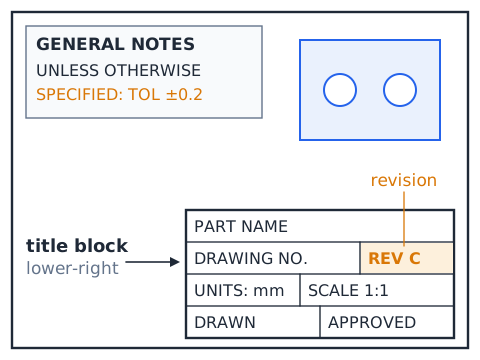
The title block commonly identifies the part name or number, drawing number, units or governing notes, scale, authorizing details, and revision. Conventions vary among organizations, so the learner must read the actual labels. Revisions distinguish superseded instructions from current ones. A notes panel may override a general convention or provide a general tolerance for dimensions that lack their own.
Title blocks and revisions — Worked interpretation
If a drawing is labeled revision C and the work order calls for revision D, the shop must obtain and review the correct revision rather than assume the previous geometry is still acceptable. Checking the drawing number is particularly important where similar parts differ by one hole.
Title blocks and revisions — Misreading to avoid
Do not treat a drawing date as proof that a sheet is current. A controlled work order or approved document system determines the authorized revision. Likewise, a general tolerance note may apply only where an individual dimension lacks its own tolerance. If a revision changes, details that look familiar can still differ in size, material or process. Verify the current title block and notes on every sheet used for the same job.
Reading a scale — Fundamentals
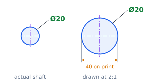
A stated scale relates the depiction to actual geometry. At 2:1, the drawing image is twice the actual linear size; at 1:2 it is half the actual size. Scale changes how geometry is pictured, not the numerical dimension written beside it. Dimensions remain authoritative unless an explicitly specified drafting procedure says otherwise.
Reading a scale — Worked interpretation
A 20 mm shaft represented at a 2:1 scale might span 40 mm on an undistorted print. The design diameter remains 20 mm. In a digital viewer, zoom factor adds another enlargement, so estimating an actual dimension from screen pixels is unreliable.
Reading a scale — Misreading to avoid
Avoid confusing 1:4 and 4:1: the former reduces the illustrated size to one quarter; the latter enlarges it fourfold. A dimension label saying 20 mm does not become 80 mm because the graphic uses 4:1. Even a drawing printed at a stated reduction can be distorted by a copier. Treat actual scale measurements as provisional unless expressly authorized, and prefer numeric specifications.
Orthographic views — Fundamentals
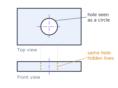
Orthographic projection represents a three-dimensional part using two-dimensional views projected in directions perpendicular to the viewing plane. Front, top, and right-side views reveal different width, height, and depth relationships. A feature may appear as a circle from one direction and a rectangular outline from another. View alignment conventions depend on projection method.
Orthographic views — Worked interpretation
Imagine a through-hole drilled vertically through a flat plate. From above, the hole appears circular; from the side, a view might depict its edges using hidden lines. Matching the same feature between views gives more reliable interpretation than treating each view as a separate part.
Orthographic views — Misreading to avoid
A single rectangular front view does not prove that the object has a rectangular cross-section throughout. Use adjacent views and notes, and verify whether first-angle or third-angle projection is specified before inferring exact view placement. Trace a single feature through views using its center, profile and location. If a feature disappears in another view, determine whether it becomes hidden instead of inventing a new shape.
Third-angle and first-angle conventions — Fundamentals
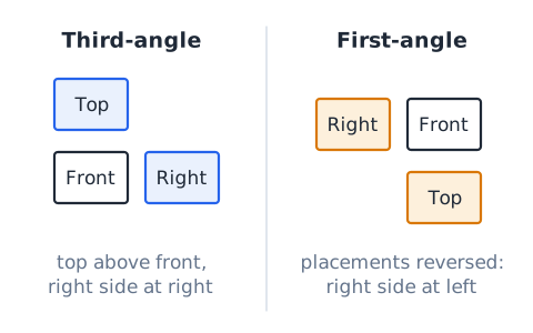
In third-angle projection, commonly used in US manufacturing drawings, a top view is generally placed above the front view and a right-side view to its right. In first-angle projection, relative placements are reversed. The projection-symbol convention and the stated drafting standard resolve ambiguity. The essential test skill is recognizing that placement depends on a declared system.
Third-angle and first-angle conventions — Worked interpretation
If a right-side view sits to the left of the front view on a properly designated first-angle sheet, it can still be correct. Read the method marker rather than labeling the sheet erroneous simply because its layout differs from another example.
Third-angle and first-angle conventions — Misreading to avoid
Never assume every American-language drawing uses third-angle projection. Imported parts, suppliers, and training materials may follow other conventions. Match the icon or explicit note to the sheet before translating view positions. View arrangement is a communications convention rather than a physical property of the object. Confirm projection before comparing top, left and right placements on suppliers’ sheets.
Isometric and pictorial views — Fundamentals
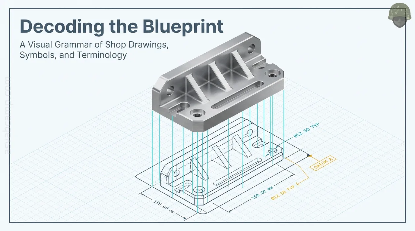
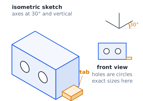
An isometric sketch gives a visually intuitive depiction of length, width, and height, typically using three principal axes. It can help identify the part and see how features interact, but it is not necessarily the source for precise manufacture. Orthographic views and actual dimensions provide the controlled shape information.
Isometric and pictorial views — Worked interpretation
A box-like housing illustrated at an angle may show two holes on the front face and one tab on the side. Use the pictorial sketch to find those features, then use plan and elevation views for exact locations and diameters.
Isometric and pictorial views — Misreading to avoid
Do not infer hidden depth or angle from pictorial appearance unless dimensioned. An attractive three-dimensional rendering can simplify an internal feature that a proper section view would show more precisely. A pictorial representation is excellent for assembly orientation, but it can conceal the underside of a hole or the wall behind a bracket. Read the dimensional views for manufacturing.
Visible, hidden and center lines — Fundamentals
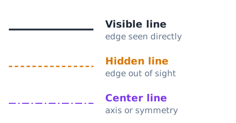
A continuous thick visible line commonly outlines an edge seen directly in that view. Short dashed hidden lines indicate edges obscured from that viewing direction. A centerline usually uses a patterned long-and-short dash to indicate an axis or symmetry line. Exact line conventions should be interpreted in their drawing context.
Visible, hidden and center lines — Worked interpretation
A rectangular side view with two parallel short-dashed vertical strokes may indicate the unseen sides of a round through-hole. A patterned line along the center of the hole establishes the axis for locating or dimensioning it.
Visible, hidden and center lines — Misreading to avoid
A dashed hidden edge is not a cut or crack on the visible face. A centerline represents location or symmetry, not solid material. Look for line weight and pattern instead of treating all dashed marks alike. Line patterns describe visibility or geometric references within the chosen view. None independently communicates a finished diameter, permissible tolerance or cut depth without supporting annotations.
Dimension lines and extension lines — Fundamentals
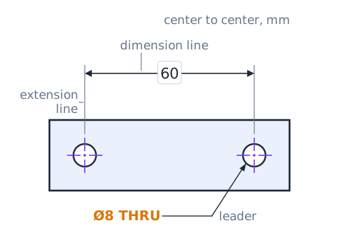
A dimension line carries a numerical value and commonly has arrowheads that delimit the measured distance. Extension lines project from the measured feature to indicate exactly which two points or surfaces the dimension describes. A leader usually connects a note or callout to a feature. Distinguishing these line roles prevents reading a note as a size.
Dimension lines and extension lines — Worked interpretation
If extension lines rise from the centers of two holes to a dimension line marked 60 mm, that number describes center-to-center spacing, not edge-to-edge distance. A leader marked Ø8 THRU identifies an individual hole instead.
Dimension lines and extension lines — Misreading to avoid
Do not measure between arrowheads without reading the attached number or endpoints. An arrow to a curved edge can identify a radius note, whereas arrowheads on a line between extensions usually identify the span being dimensioned. Pay attention to the endpoints of each extension line: a dimension may locate the center of a bore rather than its outside edge. Location and size are separate specifications.
Units and conversions — Fundamentals
Dimensions must be interpreted with the units indicated on the sheet or notes. Millimeters and inches are not interchangeable; the inch is defined exactly as 25.4 millimeters. An unlabeled number can be ambiguous without the title-block or general-notes unit convention. Carry units through every calculation.
Units and conversions — Worked interpretation
For a 2.50 in length, multiply by 25.4 mm/in to obtain 63.5 mm. For 50.8 mm, divide by 25.4 to obtain 2.00 in. Checking magnitude helps catch a conversion made backwards.
Units and conversions — Misreading to avoid
Never mix a 1/4-inch bit and a 6 mm dimension as though identical: 1/4 in equals 6.35 mm. The difference can matter for fits, so use the specified bit, drill chart, and process instructions. A numerical conversion can be exactly correct while the selected tool is still wrong. Check fit or nominal designation and verify the required precision after converting units.
Diameter and radius — Fundamentals
The diameter symbol Ø identifies a full distance across a circle through its center. The symbol R commonly identifies a radius from a center to an arc. For the same circle, diameter equals twice radius. Both usually denote finished geometric features, not tool selection, unless the instruction explicitly specifies a tool.
Diameter and radius — Worked interpretation
A plate drawing calls out Ø18 mm for a hole: its radius is 9 mm. A rounded outside corner labeled R6 mm has a 6 mm radius and an associated full-circle diameter of 12 mm if extended to a complete circle.
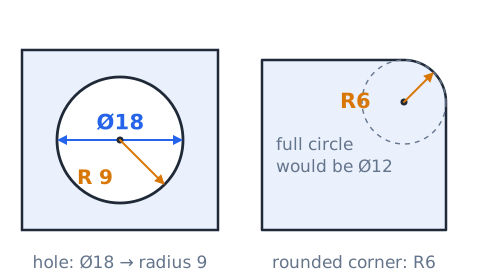
Diameter and radius — Misreading to avoid
Do not confuse Ø18 and R18. They imply very different curvatures. A radius applied to a fillet should not be treated as the diameter of an imaginary drilled hole. Circle size and edge-round size can involve the same arithmetic but different physical features. Confirm whether a radius belongs to a fillet, a curved slot or a round hole.
Hole callouts and repetitions — Fundamentals
A hole note may give quantity, diameter, and depth or through-condition. Common abbreviations include THRU for a through-hole and DEPTH for a blind hole. The mark 4X means the described feature occurs four times; it does not multiply the diameter. The drawing may use a bolt circle to locate repeated holes.
Hole callouts and repetitions — Worked interpretation
Read 4X Ø6 THRU as four separate through-holes each 6 mm in diameter. On a bolt-circle layout, a separate circle-size or coordinate dimension locates their centers. The location and hole size answer different shop questions.
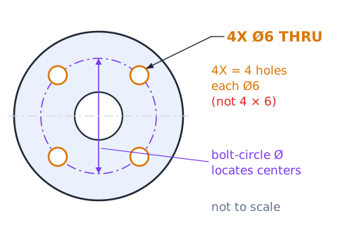
Hole callouts and repetitions — Misreading to avoid
Avoid assuming a deep cylindrical recess is a through-hole because it appears circular from above. A blind hole ends inside the material. Follow the THRU/depth designation and section details. Repetition notation can apply to holes, slots, fillets or other recurring features. Quantity by itself does not determine the pattern; a location sketch or coordinate dimensions must do that.
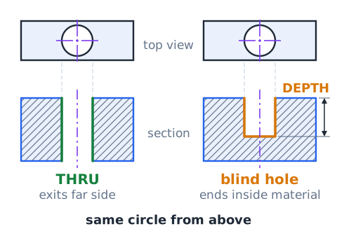
Counterbore, countersink and spotface — Fundamentals
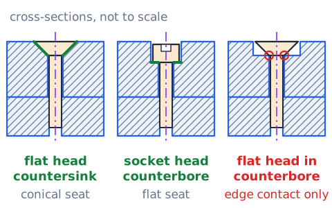
A counterbore is a cylindrical larger-diameter recess around a smaller hole, often for a socket-head screw. A countersink is a conical entry, commonly allowing a flat-head fastener to sit flush. A spotface is a shallow machined seating surface. Their callout symbols differ; explanation of the feature shape matters more than memorizing a single font glyph.
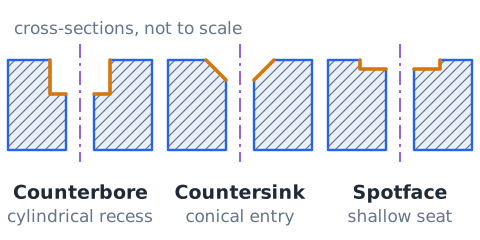
Counterbore, countersink and spotface — Worked interpretation
A flat-head screw requires a conical seat matching its head angle; a cylindrical socket-head recess would not provide the same intended seating. The shop should identify the fastener geometry from the drawing and use the specified cutter.
Counterbore, countersink and spotface — Misreading to avoid
Do not substitute a counterbore for a countersink. Both enlarge a hole entrance, but the recess cross-sections differ substantially, changing head contact and final fit. Fastener head shape influences seating style and required cutter. A wrong recess can compromise bearing contact even when the through-hole diameter is otherwise correct.
Section views and cutting planes — Fundamentals
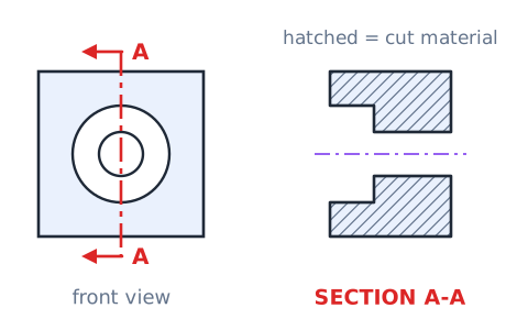
A section view depicts the exposed interior after an imagined cut along a cutting plane. Hatch marks identify material intersected by the plane, while empty areas usually represent voids. Cutting-plane arrows tell the viewing direction, and labels such as SECTION A-A identify the corresponding view. Sectioning often clarifies nested holes and wall thickness.
Section views and cutting planes — Worked interpretation
A housing section may show a thin wall and two concentric bore diameters where a normal front view would show overlapping hidden lines. Read the hatch pattern as cut material, not as surface decoration.
Section views and cutting planes — Misreading to avoid
Do not mistake hatch lines for actual grooves or scratches in a finished part. Hatch direction and spacing are conventional graphic indicators and do not generally specify machining tool paths. On sectioned assemblies, different hatch directions or patterns can help distinguish neighboring components. Use the section label and cut direction to determine what is physically exposed.
Exploded and assembly drawings — Fundamentals
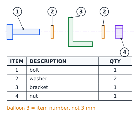
An assembly drawing shows how components fit and relate to one another. An exploded view spaces the parts to expose order and orientation; the gaps are for readability and need not represent operating clearances. A parts list or bill of materials (BOM) links item callouts with part numbers, descriptions, and quantities.
Exploded and assembly drawings — Worked interpretation
An exploded assembly may show two washers, a bracket, one bolt and one nut aligned along a common axis. Confirm the sequence using fastener callouts and the assembly notes, rather than treating pictorial spacing as a dimension.
Exploded and assembly drawings — Misreading to avoid
Item balloon 3 normally identifies a parts-list entry, not a three-millimeter measure. Always distinguish part identifiers from geometric dimensions and from process sequence labels. Exploded arrangements usually exaggerate separation to make assembly order visible. Confirm actual fastening, torque and orientation requirements using notes or process instructions, not exploded spacing.
Basic fit and clearance vocabulary — Fundamentals
Clearance is the positive difference when an internal feature is larger than a mating external feature. Interference occurs when the shaft or inserted feature is larger than the opening under specified conditions. A transition fit may exhibit either small clearance or interference depending on actual sizes. Tolerances define the range of possible conditions.
Basic fit and clearance vocabulary — Worked interpretation
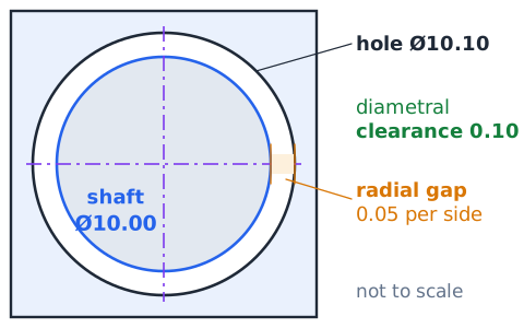
For a 10.10 mm hole and 10.00 mm shaft, the nominal diameter clearance is 0.10 mm. That is diametral clearance; radial clearance in a centered ideal model is half as large. Actual fit also depends on allowed variations.
Basic fit and clearance vocabulary — Misreading to avoid
Do not call a part “guaranteed clearance” from nominal sizes alone when tolerances overlap. Compare worst-case hole minimum and shaft maximum to decide whether clearance is assured. A positive diametral clearance does not by itself establish acceptable operating fit. The full tolerance range, thermal environment and mating geometry may change practical function.
Unilateral and bilateral tolerances — Fundamentals
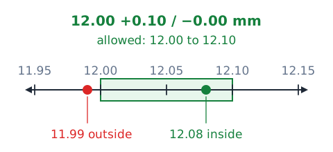
A bilateral tolerance allows variation on both sides of nominal; 20.0 ± 0.2 mm permits values from 19.8 to 20.2 mm. A unilateral tolerance allows permitted variation on one side, such as 20.0 +0.2/−0.0 mm. Unless otherwise stated, limits at endpoints are generally included in size acceptance.
Unilateral and bilateral tolerances — Worked interpretation
If a hole is specified 12.00 +0.10/−0.00 mm, 12.08 mm is inside the size limits and 11.99 mm is outside. The notation says nothing by itself about position, roundness, or surface condition.
Unilateral and bilateral tolerances — Misreading to avoid
Avoid assuming “within size tolerance” means the whole part passes inspection. Geometric controls, surface finish, material, and position may have separate specifications. When a dimension has asymmetric deviations, calculate the upper and lower limit separately. Do not invent a symmetric ± value because it looks simpler than the specified notation.
Limit dimensions and stack-up — Fundamentals
Limit dimensioning supplies a largest and smallest acceptable size, while stack-up analysis considers how individual allowed variations combine in an assembly. For the simplest linear chain, worst-case overall minimum adds all segment minima and worst-case overall maximum adds all maxima. Correlations and geometric requirements may require more advanced treatment.
Limit dimensions and stack-up — Worked interpretation
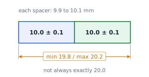
Two spacers each 10.0 ± 0.1 mm create a simple ideal stack from 19.8 to 20.2 mm. A designer cannot claim the total is always exactly 20.0 mm merely because the nominal sizes add to that value.
Limit dimensions and stack-up — Misreading to avoid
Do not replace an actual drawing’s plus/minus tolerance with an invented “typical” shop tolerance. Also do not treat this simple length-chain exercise as a complete precision fit or statistical tolerance analysis. A worst-case tolerance chain adds upper or lower segment limits, not nominal sizes only. This arithmetic applies to a simplified linear chain, not every three-dimensional assembly.
Datum and baseline measurements — Fundamentals
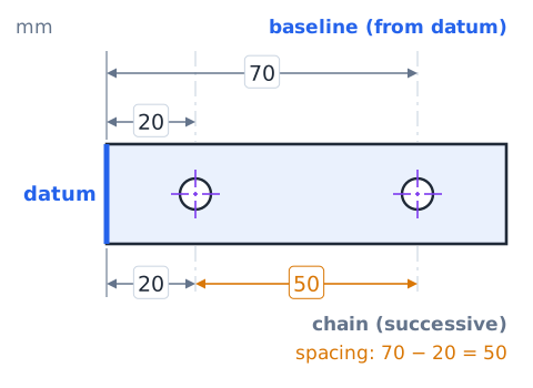
A datum is a theoretically exact reference such as a plane, axis, or point used to establish the reference framework for inspection or definition. In everyday shop tasks, a common baseline edge helps locate several features consistently. Basic coordinate dimensions from one origin reduce the accumulation of sequential measuring errors.
Datum and baseline measurements — Worked interpretation
Two hole centers lie at X=20 mm and X=70 mm from the same left-hand datum. Their nominal center separation is 50 mm. This is different from making separate 20 mm and then 50 mm measurements successively along the work.
Datum and baseline measurements — Misreading to avoid
Do not equate a scratched pencil line with a qualified datum simulator on a precision machine. Beginner drawings may use baseline concepts informally; formal GD&T datums have a more rigorous definition. A datum reference must be repeatable during measurement. Moving the origin between individual feature checks can conceal errors, even where every local ruler reading looks reasonable.
Geometric dimensioning basics — Fundamentals
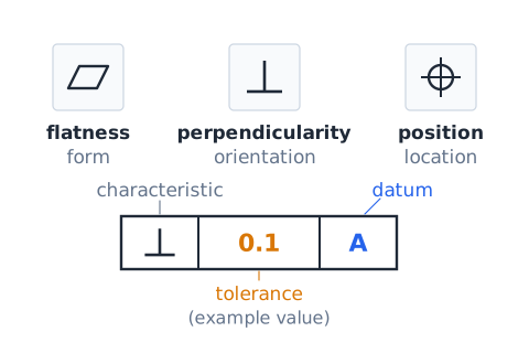
Geometric dimensioning and tolerancing, or GD&T, communicates allowable variation in form, orientation, location, or runout relative to specified references. Symbols for flatness, perpendicularity, and position represent different geometric requirements. For ASVAB-level study, recognize the purpose: controlling shape or location, not substituting for every size dimension.
Geometric dimensioning basics — Worked interpretation
A flatness requirement constrains the surface geometry; a perpendicularity requirement concerns orientation relative to a stated datum. A nominal 90-degree visual corner does not automatically specify either control unless stated.
Geometric dimensioning basics — Misreading to avoid
Do not invent a full GD&T acceptance rule without the feature control frame and referenced standard. Actual inspection may depend on datum setup and material modifiers beyond basic shop-vocabulary coverage. GD&T symbols convey specific constraints that ordinary plus-or-minus size limits may not control. Basic learners should recognize the question being asked without guessing absent feature frames.
Surface finish, roughness and process notes — Fundamentals
A surface finish or texture specification describes required surface characteristics and may carry a roughness value. A machining note can direct process or treatment, while deburr means remove sharp edges or burrs left by cutting. These requirements are separate from the overall dimensions: a correctly sized part can still be unsafe or functionally unsuitable when the finishing requirement is ignored.
Surface finish, roughness and process notes — Worked interpretation
A sliding bearing seat could require specified surface texture even when its diameter is within tolerance. A note “REMOVE BURRS” signals that stray sharp metal remnants should not remain on affected edges after machining.
Surface finish, roughness and process notes — Misreading to avoid
Do not assume a mirror-like appearance proves a surface meets measured roughness requirements. Also, never interpret a texture symbol as a general permission to grind away dimensioned material. A roughness or finish requirement can affect sliding, sealing and fatigue performance. Visual smoothness alone is not proof that the measured finish, processing or deburring requirements are satisfied.
Thread callouts and pitch — Fundamentals
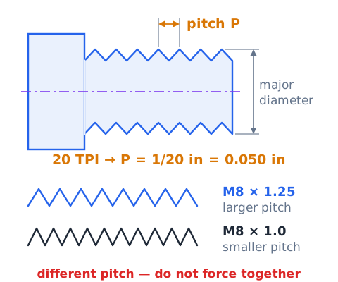
A thread callout commonly identifies nominal size and a pitch or threads-per-inch, plus series, class or other fit details. In metric terminology, M8 × 1.25 indicates a nominal 8 mm major diameter and a pitch of 1.25 mm. In US thread terminology, 1/4-20 identifies a nominal quarter-inch major diameter with 20 threads per inch.
Thread callouts and pitch — Worked interpretation
For a simple single-start screw with 20 TPI, adjacent-thread axial pitch is 1/20 in = 0.050 in. A screw marked M8 × 1.25 has a larger pitch than M8 × 1.0; these threads should not be forced together.
Thread callouts and pitch — Misreading to avoid
A matching nominal diameter does not guarantee interchangeable fasteners. Pitch, thread system, class and direction must be checked against the callout. “M” is not automatically a tool or material grade label. Thread shape, pitch and system must all agree before assembly. Forcing unmatched metric and inch fasteners can strip material and make a visually minor dimension error expensive.
Angles, chamfers and tapers — Fundamentals
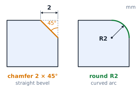
An angle callout describes the relationship between directions or surfaces; a chamfer is a beveled edge, often described by length and angle such as 2 × 45°. A taper changes size along length, sometimes given as an angle or dimensional change per unit length. The notation’s context determines whether “2X” is a quantity or whether the ‘2’ is a linear chamfer size.
Angles, chamfers and tapers — Worked interpretation
A 2 mm × 45° chamfer is a sloped edge treatment, not a 2 mm radius round. A 30° wall angle should not be guessed from the sketch, especially when the projection distorts appearance.
Angles, chamfers and tapers — Misreading to avoid
The letter X has multiple uses in drafting. “4X Ø8” means four occurrences; “2 × 45°” attached to a chamfer specifies its geometric parameters. Read the whole callout rather than one character. An angular note may refer to a chamfer, a taper or an overall part edge. Pair the angle with its exact leader and geometric feature before selecting an operation.
Welding and joining symbols — Fundamentals
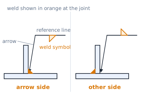
A welding symbol may use a reference line, arrow and basic weld symbol to identify joint form, location, and sometimes size or length. An arrow-side versus other-side indication can be significant in welding notation. Actual welding requires qualified processes, materials, and safety procedures; a basic drawing-recognition course does not authorize fabrication.
Welding and joining symbols — Worked interpretation
If a weld note points to the intersection of two metal plates, first identify the joint and reference line. If no trained welding support or current qualified instruction exists, the proper shop action is to clarify the requirement instead of improvising a bead shape.
Welding and joining symbols — Misreading to avoid
A welding symbol is not the same as a common electrical ground symbol or a hazard pictogram. Do not infer exact weld side or dimensions from generic imagery; read the full recognized symbol and governing standard. Weld symbols are technical process instructions and can carry safety consequences. An entry-level symbol-identification exercise is not training to weld without qualified supervision.
Electrical and hydraulic schematics — Fundamentals
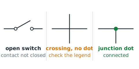
A schematic simplifies physical layout to show functional connections. Electrical circuit symbols depict components such as switches, fuses, resistors, motors, and grounds; flow and fluid-power drawings depict valves, pumps and actuators. A line in a schematic usually means a functional path, not actual wire or pipe length or precise installation route.
Electrical and hydraulic schematics — Worked interpretation
An open switch symbol means its electrical contact is not closed in the drawn state. Two crossed lines without a joining dot may be different conductors depending on the convention; refer to the sheet’s legend and node symbols before deciding whether they connect.
Electrical and hydraulic schematics — Misreading to avoid
Do not confuse a schematic’s functional symbol with a literal miniature photograph of the component. Physical connector placement and routing require installation drawings, labels and safety instructions. Reading a schematic demands interpreting connection symbols and legend conventions. A crossing without a clearly defined junction is a reason to consult the convention, not to guess.
Safety signs, pictograms and labels — Fundamentals
A shop can contain warning signs, mandatory protective-equipment instructions, chemical hazard pictograms, lockout tags, and other labels. OSHA’s hazard communication program uses specific pictograms such as flame and corrosion to communicate chemical hazard classes. The meaning depends on the complete label, not just its color. Read signal words and precautionary statements.
Safety signs, pictograms and labels — Worked interpretation
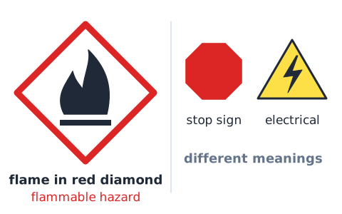
A red diamond pictogram with a flame identifies a potential flammability-related hazard on a chemical label; it is not a stop sign or a generic electrical warning. For unknown products, consult the manufacturer label and applicable safety data sheet.
Safety signs, pictograms and labels — Misreading to avoid
Do not assume every red diamond has identical meaning, nor that a flame pictogram identifies an active fire. Different workplace signs follow different rules, and the hazard-communication symbols should be interpreted in their specified context. Chemical hazard pictograms identify potential properties, not the current operating state of a substance. Read the full label and applicable safety data sheet before handling materials.
Inspection and reading workflow — Fundamentals
An effective first pass is: confirm drawing and revision, locate units and scale, read general notes, identify view and projection, locate the feature, read the exact callout, and confirm any limits or safety requirements. This staged process minimizes errors caused by guessing from pictorial appearance. In multiple-choice questions, eliminate interpretations that violate the symbol’s fundamental definition.
Inspection and reading workflow — Worked interpretation
A student sees 2X Ø10 THRU on a plate. First locate two hole centers from the plan view, then read the callout: two 10 mm through-holes. The symbol Ø controls diameter and THRU controls penetration, while the actual center positions require separate location dimensions.
Inspection and reading workflow — Misreading to avoid
Avoid solving from one cropped symbol with all context hidden. A legend, note or title block may settle a genuine ambiguity. In real work, escalate missing or conflicting information rather than choosing an unsafe interpretation. If a question omits a necessary unit, revision or view, the safest technical response is to identify the missing information. Real shop quality depends on clear instructions and verification.
Worked example: a dimensioned mounting plate
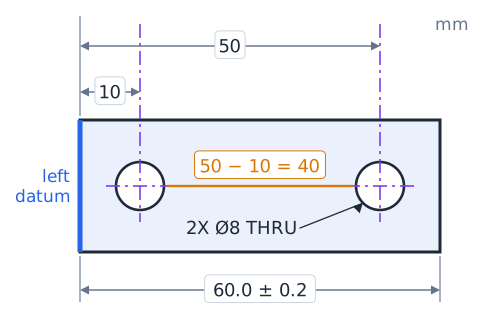
The drawing shows a rectangular mounting plate with a 60.0 ± 0.2 mm overall width. Two Ø8 THRU holes are located by center coordinates X=10 mm and X=50 mm from one left datum edge. Their nominal spacing is 40 mm, and each hole is 8 mm in diameter; the callout does not describe the distance between centers. For overall width, allowed values from 59.8 through 60.2 mm satisfy that one size requirement, although hole positions and other requirements must also be verified. Read one callout at a time.
Worked example: clearance and unit conversion
A dimensioned hole is 0.500 in in diameter and a corresponding shaft is 0.480 in in diameter. Nominal diametral clearance is 0.020 in, which is 0.508 mm. For a concentric idealized part, the radial gap is 0.010 in, or 0.254 mm. Distinguish diametral from radial clearance; neither figure confirms a guaranteed fit if the part tolerances are not given.
Worked example: selecting an appropriate view
Suppose a drawing of a housing is confusing because two circular bores occupy overlapping locations in the front view. Look for a cutting-plane line marked A-A and a corresponding SECTION A-A: the sectional view can distinguish the wider recess from the smaller passage by showing their profiles against hatched material. Do not mistake the sectional hatching for machining marks. Use dimension callouts from the relevant view to find each diameter and the actual depth.
Exam strategy: eliminate misread symbols
On a time-limited question, first determine what is being asked: identity of a symbol, actual dimension, permitted size range, feature count, or required shop action. Scan for Ø, R, X, THRU, revision labels, line patterns, and units. Reject answers that swap diameter and radius, multiply a dimension by a view scale, or identify an item balloon as a dimension. For arithmetic, carry units and check order of magnitude. Real-world drawings with conflicting notes require clarification, not guessing.
Final review: one-minute shop drawing checklist
Confirm part ID and revision; locate units and drawing notes; identify projection and views; distinguish visible, hidden and center lines; interpret dimension arrows and leader lines; separate diameter, radius, quantity and depth; compute allowable limits exactly; check section and BOM conventions; identify safety labels from their full context. Never assume a picture alone guarantees a safe or manufacturable part.
 English ▾