 ASVAB Camp
Learning outcomes and examination relevance
By the end of this lesson you should be able to tell a fixed pulley from a movable one, count the rope segments that hold up a load, and use that count to find the ideal effort force and how far the rope must be pulled. You will also compare actual and ideal mechanical advantage, compute work and efficiency, and predict the speed and turning direction of a belt-driven pulley using
These skills appear often on ASVAB Mechanical Comprehension items.
One word, two different pulley jobs
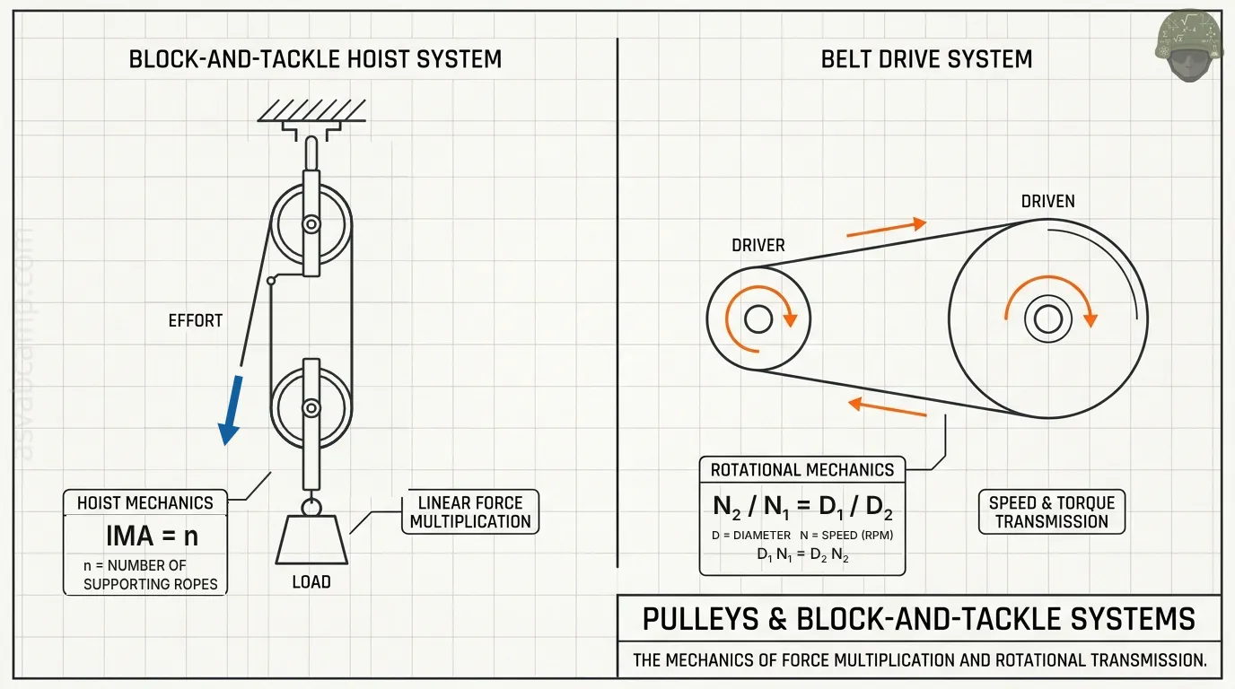
The word pulley covers two quite different machines. In a hoist, a grooved wheel guides a rope or cable so that a person or winch can raise a load, and the question is how much force is needed. In a belt drive, pulleys are mounted on shafts and a belt carries rotation from one shaft to another, and the question is usually speed in rpm. Before solving, decide which job the pulleys in the problem are doing.
Fixed pulley: a change in direction
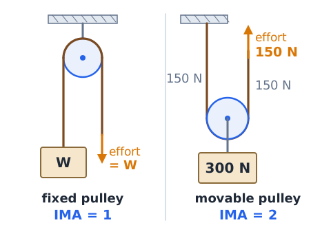
A fixed pulley is attached to a beam or ceiling and does not move up or down. Its only job is to redirect the rope, so you can pull down to make a load go up. In the ideal case the effort equals the load, so the mechanical advantage is 1. A flagpole halyard is a good example: pulling the rope down 3 m raises the flag 3 m, and the force is no smaller.
Movable pulley: shared upward support
A movable pulley hangs from the rope and travels with the load. The rope runs under it, so two rope segments pull up on it at once. If one end is anchored overhead and you pull the other end upward, each segment carries half the load, giving an ideal mechanical advantage of 2. A 300 N load needs only about 150 N of effort, but the load rises only half as far as you pull.
Block and tackle: fixed and moving blocks
A block is a frame holding one or more sheaves (the grooved wheels). A block and tackle combines an upper block fastened to a support and a lower block that carries the load, with one continuous rope threaded back and forth between them. The threading pattern is called reeving. More passes between the blocks means more rope segments sharing the load, so the effort drops while the length of rope you must pull grows.
Count the load-supporting segments
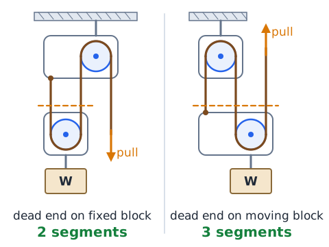
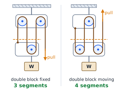
The reliable way to find the ideal mechanical advantage of a pulley system is to count the rope segments that directly hold up the moving block and its load. Draw an imaginary line just above the moving block and count how many rope segments it cuts. If that count is n, then in the ideal case each segment carries load divided by n, so
Ignore segments that touch only the fixed block.
Why the rope anchor matters
Where the rope end is tied changes the count. If the dead end is tied to the fixed upper block, it does not pull on the moving block, so the count is even (2, 4, 6). If the dead end is tied to the moving block, that segment also holds the load, and the count becomes odd (3, 5). Two systems with the same number of sheaves can therefore differ by one in mechanical advantage.
Ideal mechanical advantage is dimensionless
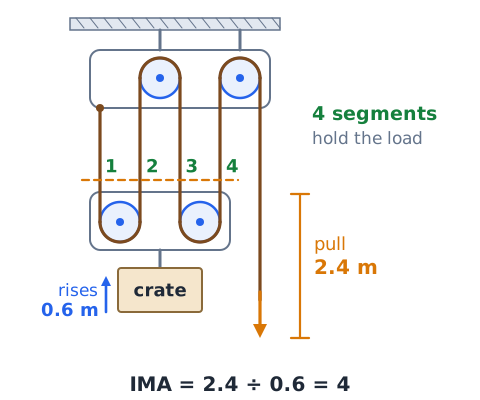
Ideal mechanical advantage (IMA) is a pure number with no units. For a pulley system it equals the number of supporting segments, or equivalently the ratio of distances:
Both distances are in the same unit, so meters cancel meters. If you pull 2.4 m of rope to raise a crate 0.6 m, the IMA is 4, not 4 meters.
Actual mechanical advantage uses measured forces
Actual mechanical advantage (AMA) compares the load force to the effort force someone really applies, including friction and the weight of moving parts:
If a 450 N engine part needs a measured pull of 180 N, the AMA is 2.5. The AMA is always less than the IMA in a real machine because some effort is spent fighting friction.
Effort and resistance forces
Two forces appear in every machine problem. The effort force (also called input force) is what you or a motor apply to the rope or handle. The resistance force (also called the load or output force) is what the machine works against, usually the weight of the object being lifted. Weight equals mass times gravity, so a 40 kg load has a weight of about
Keep pounds and newtons separate; never mix them in one ratio.
Rope travel is the price of force multiplication
A pulley system cannot reduce force for free. Every supporting segment must shorten by the same amount the load rises, and all that shortening comes out through the rope end you pull. With n segments,
Lifting a motor 0.4 m with a three-segment tackle means hauling in 1.2 m of rope. Less force, more distance.
Ideal work balance
Work is force times distance moved in the direction of the force, measured in joules. In an ideal machine, work in equals work out:
For example, raising a 400 N box 0.5 m takes 200 J. A tackle with four segments lets you do that with 100 N pulled over 2 m, which is also 200 J.
Efficiency includes real energy losses
Real pulleys lose energy to bearing friction, rope bending and rubbing. Efficiency tells how much input work becomes useful output:
If you put in 300 J and the load gains 270 J, the efficiency is 90 percent. It can never exceed 100 percent.
Efficiency is not mechanical advantage
Mechanical advantage tells how much a machine multiplies force. Efficiency tells how much energy survives the trip through the machine. A six-segment tackle can have a large IMA yet poor efficiency because of all its sheaves. The two connect through
So a hoist with IMA 4 and AMA 3 is 75 percent efficient. A high MA does not imply a high efficiency.
Static balance and accelerating loads
The simple rule effort equals weight divided by n applies when the load hangs still or moves at a steady speed, because then the forces balance. To speed a load up, the rope must also supply the extra force ma. For a 50 kg load on two supporting segments, holding it steady needs about 245 N per segment (total 490 N). Accelerating it upward at 0.4 m/s squared needs a total of
or 255 N per segment. Exam questions usually assume steady motion.
Direction of the effort force
In a hoist, the direction you pull does not change the ideal force needed when the rope leaves a fixed sheave, because that sheave only redirects the rope. Pulling down is often easier because you can use your body weight. But pulling down on a rope that leaves the upper block adds your pull to the load on the ceiling hook, while pulling up from the moving block can add one supporting segment.
Rope tension in the ideal model
In the ideal model the rope is weightless, does not stretch and runs over frictionless sheaves. Under those assumptions the tension is the same everywhere along one continuous rope, and it equals the effort you apply. That is why each supporting segment carries the same force. With four segments each at 150 N, the moving block receives
N of upward support. In a real tackle the tension changes slightly at each sheave because of friction.
Pulley weight and suspended hardware
The moving block rises with the load, so its own weight is part of what the rope must lift. Add the weight of the moving block, hook and any sling to the load before dividing by the number of supporting segments. The fixed block does not ride with the load, so its weight is carried by the ceiling, not by the rope. If a problem says the pulleys are weightless, simply ignore them.
Ceiling and anchor reactions
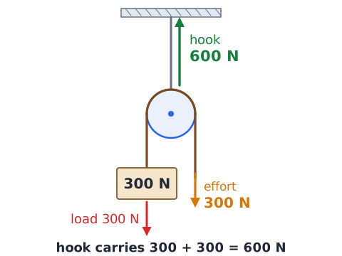
The support holding the fixed block must carry every rope segment that pulls on that block, plus the block's own weight. With one fixed pulley lifting a 300 N load, the rope pulls down 300 N on the load side and 300 N on the effort side if you pull straight down, so the hook carries about 600 N. Pulling sideways or upward changes this total. Supports must be rated for that full reaction, not just the load.
Angle of rope segments changes support
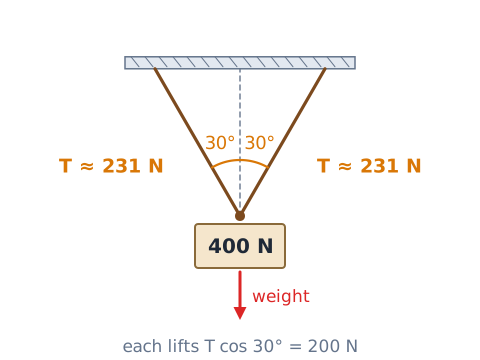
Only the vertical part of a rope's tension holds a load up. When supporting segments are tilted, each segment's lifting share is , where is measured from vertical. Two segments each at 30 degrees from vertical holding 400 N need
which is more than the 200 N needed if they hung straight. Wider angles demand more tension.
One fixed sheave is not a moving sheave
A common trap is a diagram with one pulley bolted overhead and a rope over it to the load. Only one segment, the one tied to the load, holds the load up; the other segment is your pull. The IMA is 1. Mechanical advantage of 2 appears only when the pulley itself rides on the load and two segments pull up on it. Check whether the sheave moves before counting.
Mechanical advantage of simple systems
Some standard ideal values are worth memorizing. A single fixed pulley gives IMA 1. A single movable pulley with one end anchored gives IMA 2. A gun tackle (one sheave on each block) gives 2, or 3 if rove so the pulled end leaves the moving block. A luff tackle (one double block and one single block) gives 3 or 4, depending on which block moves, and two double blocks give 4 or 5, again depending on reeving. In every case, confirm by counting segments.
Identify the system of interest
Before applying any formula, decide which object you are analyzing. For the load, include the moving block and everything that rises with it, then look at the rope segments pulling up on that group. For the ceiling hook, look at the fixed block and every segment pulling down on it. Mixing these two views leads to wrong counts. Circle the moving parts, list the forces crossing your boundary, and then balance them.
Rope end pulled versus rope end anchored
The pulled end counts as a supporting segment only when it leaves the moving block and you pull in the same direction the load moves, usually upward. If the pulled end comes off the fixed block and you pull downward, it is just the effort line and is not counted. The anchored dead end counts only when it is tied to the moving block. Trace both ends of the rope before you count.
Rope displacement through reeving
Because each supporting segment shortens by the load's rise, the rope length pulled equals the number of segments times the lift. A five-segment tackle lifting a pallet 0.3 m requires
If the rope pull seems shorter than the lift in an answer choice, the choice is wrong for a pulley that reduces force.
Speed of load versus speed of rope
Distance ratios carry directly over to speeds, since both happen in the same time. With n supporting segments,
If a worker hauls rope at 0.6 m/s on a three-segment tackle, the load rises at 0.2 m/s. A system that multiplies force always slows the load relative to the rope.
Using a load diagram to avoid double counting
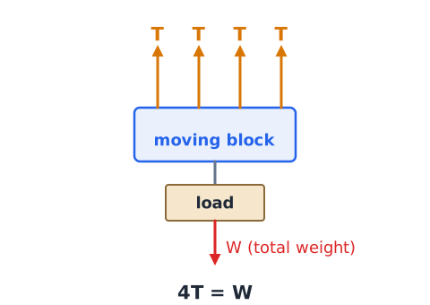
A quick free-body sketch prevents counting the same segment twice. Draw the moving block as a box with the load hanging below. Draw an arrow up for each rope segment attached to or wrapping around that box, and one arrow down for the total weight. Label each upward arrow T. Then set the number of T arrows times T equal to the weight. A segment that merely passes between two fixed sheaves never touches the box and gets no arrow.
When pulleys are paired with another machine
Hoists often combine a pulley system with a winch, lever or gear. In the ideal case, the overall mechanical advantage of machines in series is the product of their individual values:
A hand winch with IMA 6 feeding a two-segment tackle gives an ideal total of 12. Overall efficiency is likewise the product of the separate efficiencies, so losses stack.
A belt drive is a rotational transmission
A belt drive uses two or more pulleys on separate shafts linked by a loop of belt. Its purpose is to transmit rotary motion and power from a driving shaft, such as a motor, to a driven shaft, such as a fan, pump or saw arbor. By choosing pulley sizes, the designer can raise or lower the driven speed. Belts also absorb shock and can span distances where gears would be impractical. It does not lift loads with rope strands.
Driver and driven are role labels
The driver (or driving pulley) is the one connected to the power source, usually the motor. The driven pulley is the one receiving power and turning the machine. These names describe roles, not sizes: the driver can be larger or smaller than the driven pulley. Always identify which pulley the motor turns before plugging numbers into a speed formula, or you will invert the ratio.
No-slip belt-drive speed relation
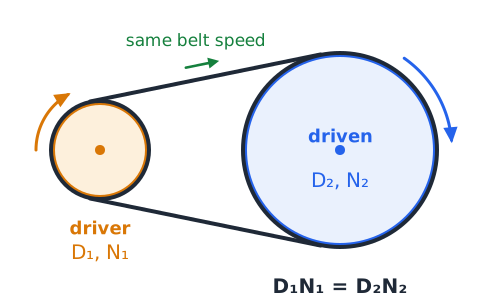
If the belt does not slip, every point on the belt moves at the same linear speed, so the rim speed of both pulleys must match. That gives
where D is effective diameter and N is speed in rpm; subscript 1 is the driver and 2 the driven. Rearranged,
Diameters only need the same units as each other.
Larger driven pulley reduces RPM
When the driven pulley is larger than the driver, it turns more slowly. Each turn of the big pulley needs more belt to pass, so it takes several turns of the small driver to complete one. An 80 mm motor pulley at 1,800 rpm driving a 240 mm pulley gives
Speed falls by the same factor the diameter rises, three times here.
Smaller driven pulley increases RPM
When the driven pulley is smaller than the driver, it turns faster, because its rim is shorter and a given length of belt wraps it more times. A 200 mm driver at 900 rpm feeding a 150 mm driven pulley gives
So shrinking the driven pulley, with the driver unchanged, raises output speed.
Open belt drive direction
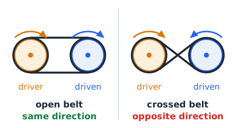
In an open belt drive, the belt runs straight between two pulleys on parallel shafts without twisting, like a loop around two wheels. Viewed from the same end, both pulleys turn in the same direction: if the driver turns clockwise, so does the driven pulley. Pulley sizes affect speed but never reverse direction in an open belt. This is the arrangement in most car engines and shop machines.
Crossed belt drive direction
In a crossed belt drive, the belt is twisted into a figure eight so the two runs cross between the pulleys. That crossing reverses rotation: viewed from the same side, the driven pulley turns opposite to the driver. The speed formula
still applies to the magnitudes. Crossed belts wrap more of each pulley, which improves grip, but the belts rub where they cross, so they wear faster and suit only light duty.
Pitch diameter versus outside diameter
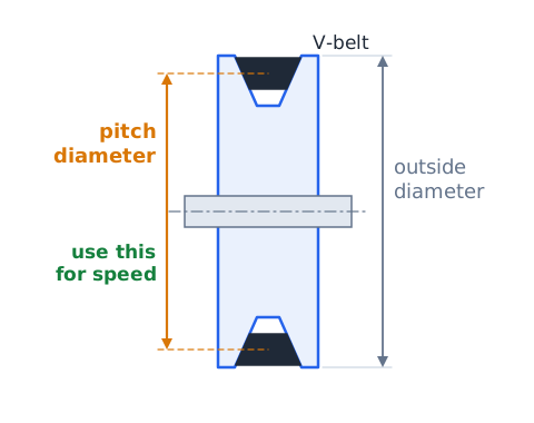
For speed calculations, use the effective or pitch diameter, which is the diameter where the belt actually rides, not the outer rim of the pulley. A V-belt sits down inside its groove, so its working diameter is smaller than the pulley's outside diameter. Flat belts ride on the surface, so the two are nearly equal. Exam problems usually give the effective diameter directly; if both are listed, choose the one marked effective or pitch.
Belt surface speed
Belt speed is how fast the belt moves along its path. In one turn, a point on the pulley rim travels one circumference, . Multiply by turns per second:
with D in meters and N in rpm, giving m/s. A 0.10 m pulley at 1,500 rpm drives its belt at about 7.85 m/s, and in a no-slip drive both pulleys share that speed.
Compound belt-drive stages
A compound drive has two or more belt stages. The driven pulley of the first stage shares a shaft with the driver of the second, so those two pulleys always turn at the same rpm even if their sizes differ. Work stage by stage: find the intermediate shaft speed, then use it as the input to the next belt. The overall speed ratio is the product of the stage ratios, so large reductions can be built from modest pulleys.
Ideal torque relationship in a belt drive
Power is torque times angular speed, so in a lossless drive what is lost in speed is gained in torque. The torque ratio is the inverse of the speed ratio:
A drive that cuts speed by a factor of four ideally multiplies torque by four, so a 10 N·m motor torque becomes 40 N·m at the output shaft. Speeding up a shaft reduces its torque.
Tight-side and slack-side belt tension
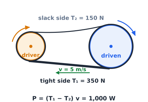
A running belt is not equally tight on both runs. The side being pulled toward the driver is the tight side, with tension ; the other run is the slack side, . The difference between them is the net force that turns the driven pulley. Power transmitted equals that difference times belt speed:
For 350 N and 150 N at 5 m/s, the power is 1,000 W.
V-belt and flat belt basics
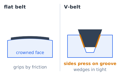
A flat belt is a thin, wide band that grips by friction on a smooth or slightly crowned pulley face. It runs quietly and suits long spans and high speed. A V-belt has a trapezoid cross section that wedges into a matching groove, so the sides press hard against the pulley and grip much better for the same tension. That makes V-belts common on compact motors, compressors and engines. Both can still slip under overload.
Synchronous or timing belts
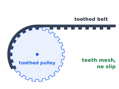
A timing belt, also called a synchronous belt, has teeth molded on its inner surface that mesh with grooves on toothed pulleys. Because it engages like a gear, it cannot slip under normal operation, so the shafts keep an exact speed ratio and stay in step. Engines use timing belts to keep the camshaft synchronized with the crankshaft. For toothed pulleys, the speed ratio equals the inverse ratio of tooth counts.
What an idler pulley does
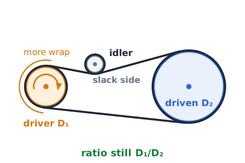
An idler is a pulley that presses on or guides the belt but does not drive any machine. It may take up slack, increase the wrap angle on a small pulley or route the belt around an obstacle. Since the belt speed is the same everywhere, an idler does not change the speed ratio between driver and driven: it still equals . The idler simply turns at whatever rate its own diameter dictates.
Slip and creep are real effects
The no-slip formula is an ideal. Real friction belts lose a small amount of speed in two ways. Creep is the slight stretching and relaxing as the belt moves from the tight side to the slack side, which causes a loss of around 1 to 2 percent. Slip is the belt sliding over the pulley when the load is too high or the tension too low. If the ideal driven speed is 1,200 rpm and you measure 1,170 rpm, the shortfall is
Overtension is not a universal cure
Tightening a slipping belt can help, but too much tension creates new problems. Excess tension loads the shaft bearings heavily, heats and stretches the belt, and can bend shafts or shorten motor life. A belt that is glazed, cracked or the wrong size will not be fixed by more tension. The right tension is what the manufacturer specifies, often checked by measuring how far the belt deflects under a set push at mid span. Too tight and too loose both waste energy and wear parts.
Misalignment and wear symptoms
Pulleys that are not lined up in the same plane, or whose shafts are not parallel, force the belt to run at an angle. Warning signs include squealing, a belt that walks off or rides high in the groove, uneven wear on one side, frayed edges, black dust under the drive and excess vibration. Worn pulley grooves lower the belt's effective diameter and change the speed ratio. Fixes include aligning pulleys with a straightedge, replacing worn parts, and replacing matched belts as a set.
Exposed belt nip points
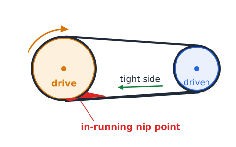
Where a belt runs onto a pulley, it forms an in-running nip point, a narrowing gap that can pull in fingers, gloves, hair, loose sleeves or jewelry in a fraction of a second. The tight side near the drive pulley is especially hazardous. A belt moving at 7 m/s covers about 0.7 m in just 0.1 s, faster than a person can react. For this reason, belt and pulley drives must be kept guarded, and nobody should reach near a running belt.
Guarding depends on actual equipment
Workplace safety rules, including OSHA machine guarding requirements, call for covering belts, pulleys and other power transmission parts that workers could contact. The right guard depends on the specific machine, its height, its openings and how it is serviced, so follow the manufacturer's manual and site procedures. Before adjusting or replacing a belt, the machine must be shut off and locked out so it cannot start unexpectedly. A guard removed for service must be reinstalled before restart.
Example: one fixed pulley
Problem: A worker raises a 240 N bucket of tools to a scaffold using a single pulley bolted to a beam. What ideal effort is needed, and how much rope is pulled to raise the bucket 2 m?
Step 1: The pulley does not move, so only one segment holds the bucket. IMA = 1.
Step 2: Effort =
Step 3: Rope pulled = 1 times 2 m = 2 m. The benefit is only pulling downward.
Example: simple movable pulley
Problem: A 500 N sandbag hangs from a movable pulley. One rope end is tied overhead, and a worker pulls the other end up. Find the ideal effort and the rope pulled to lift it 0.6 m.
Two segments support it, so IMA = 2. Effort =
Rope pulled = 2 times 0.6 = 1.2 m.
Example: four supporting strands
Problem: A mechanic lifts a 1,200 N transmission with a block and tackle. Four rope segments run up from the lower block. Find the ideal effort and the rope pulled to raise the transmission 0.5 m.
Rope pulled = 4 times 0.5 = 2 m. Check: 300 N times 2 m = 600 J, matching 1,200 N times 0.5 m.
Example: a measured-effort hoist
Problem: A three-segment hoist lifts a 900 N crate. The measured pull on the rope is 400 N. Find the IMA, AMA and efficiency.
IMA = 3 (supporting segments).
The hoist is 75 percent efficient; friction raised the effort from the ideal 300 N to 400 N.
Example: hoist plus moving-block weight
Problem: A four-segment tackle lifts a 760 N motor. The lower block and hook weigh 40 N together. Find the ideal effort.
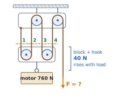
Step 1: The lower block rises with the motor, so total lifted weight =
Ignoring the block weight would give 190 N, which is too low.
Example: belt-driven fan
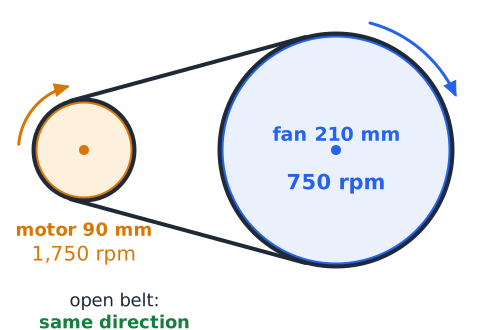
Problem: A 90 mm motor pulley turning 1,750 rpm drives a 210 mm fan pulley with an open belt. Find the fan speed and direction.
The fan turns in the same direction as the motor because the belt is open.
Example: speeding up a drive
Problem: A 180 mm driver at 600 rpm turns a 72 mm pulley on a grinder shaft. Find the grinder speed.
The driven pulley is smaller, so the answer should be faster than 600 rpm, and it is.
Example: two belt-drive stages
Problem: A 120 mm pulley at 1,500 rpm drives a 300 mm pulley. On the same shaft, an 80 mm pulley drives a 160 mm pulley. Find the final speed.
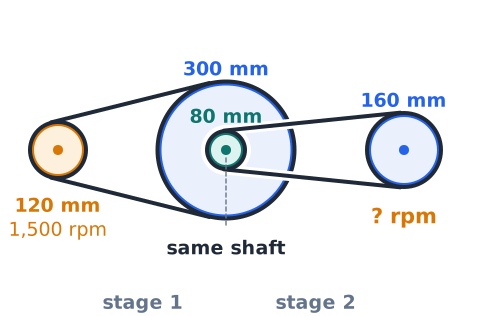
Stage 1: 1500 times
The 80 mm pulley also turns at 600 rpm.
Stage 2: 600 times
Example: interpreting belt travel speed
Problem: A pump pulley with 0.15 m effective diameter turns at 1,200 rpm. How fast does the belt move?
Every point on the belt moves at about 9.4 m/s.
Example: work and efficiency
Problem: A rigger lifts a 600 N beam 1.5 m with a four-segment tackle, pulling 6 m of rope with a measured force of 180 N. Find the efficiency.
Output work = 600 times 1.5 = 900 J. Input work = 180 times 6 = 1,080 J.
The other 180 J became heat from friction.
Solve pulley diagrams in five checks
First, find the moving block: the sheave or hook that rises with the load. Second, count every rope segment pulling up on it, including a dead end tied to it or a pulled end leaving it upward. Third, add any moving-block weight to the load. Fourth, divide by the count for the ideal effort, and multiply the lift by the count for rope travel. Fifth, if a measured force or efficiency is given, adjust: the real effort must be larger than the ideal one.
Use direction and scale to check answers
Many wrong choices fail a quick sense check. In an ideal hoist, the effort is never more than the load, and the rope pulled can never be shorter than the lift. In a belt drive, the larger pulley always turns slower, and an open belt never reverses direction while a crossed belt always does. If your result has the driven pulley speeding up while it is the bigger one, you inverted the ratio. Estimate first, then calculate.
Common mistake: counting wheels instead of ropes
Many learners count the sheaves and call that the mechanical advantage. That fails because a fixed sheave adds no support, and reeving decides whether the count is even or odd. A tackle with two sheaves on top and one below can give 3 or only 2 if one sheave is unused. The fix is to ignore the wheels and count only rope segments holding up the moving block, as
requires.
Common mistake: confusing RPM and force
Belt-drive and hoist questions use different ratios, and mixing them causes errors. A belt drive trades speed for torque; it does not reduce the force needed to lift a hanging weight with rope strands. Another slip is assuming a bigger pulley means more speed. The fix: for belts, use
for speed and remember torque moves opposite to speed. For hoists, use segment counts for force and distance.
Common mistake: ignoring the word actual
When a question says actual, measured or real, the ideal answer is wrong. Actual mechanical advantage uses the effort really applied, which includes friction, so it is smaller than the ideal value. Students often answer with the segment count anyway. For example, a four-segment hoist lifting 800 N with a measured pull of 250 N has AMA
not 4. Read the stem for these key words and choose the formula that matches.
Common mistake: using the wrong diameter
Using the outside rim diameter of a V-groove pulley, or mixing radius with diameter, gives the wrong speed ratio. The belt rides at the pitch diameter, so that is what sets the rim speed. Another error is mixing millimeters on one pulley with centimeters on the other. The fix: use effective diameters for both pulleys in the same unit, or use radii for both, since the ratio is the same either way.
Guided drill: count and then calculate
Prompt: A load of 600 N hangs from a lower block with three supporting segments. Ideal effort? Answer: 200 N.
Prompt: The same load must rise 0.8 m. Rope pulled? Answer: 2.4 m.
Prompt: The measured effort is 240 N. AMA? Answer: 2.5.
Guided drill: same-shaft logic
Prompt: Two pulleys of 60 mm and 180 mm are keyed to one shaft turning 450 rpm. How fast does each turn? Answer: both turn at 450 rpm, since they share a shaft.
Prompt: The 60 mm pulley belts to a 120 mm pulley. Its speed? Answer: 450 times
Prompt: Which pulley's rim moves faster, the 60 mm or the 180 mm? Answer: the 180 mm one, three times faster.
Guided drill: choose a safe response
Prompt: A V-belt squeals at startup and you want to check tension. What comes first? Answer: shut the machine off and lock it out so it cannot restart, then remove the guard.
Prompt: The guard is cracked but the machine still runs. Keep using it? Answer: no, report it and have the guard repaired or replaced before use.
Prompt: A coworker wants to slip a rag onto a moving belt to quiet the noise. Safe? Answer: no, the in-running nip point can pull in the rag and the hand holding it.
Final recall and self-test checklist
Can you explain why a single fixed pulley has IMA 1 and a single movable pulley has IMA 2? Can you count supporting segments on the moving block and use
? Can you add moving-block weight to the load? Do you know AMA uses measured effort and efficiency equals AMA divided by IMA, or work out over work in? For belts, can you apply
explain why the larger pulley turns slower, state that open belts keep direction and crossed belts reverse it, find belt speed with , and multiply stages in a compound drive? Can you name the hazard of a nip point and the need for guards and lockout?
 English ▾