 ASVAB Camp
Learning objectives and ASVAB scope
By the end of this lesson you should be able to explain how a ramp, a wedge, and a screw let a smaller effort move a larger load by spreading the effort over a longer distance. You will compute ideal mechanical advantage , actual mechanical advantage , screw lead, torque, and efficiency, and you will recognize the safety limits that apply when these machines hold real loads.
Three machines built around a slope
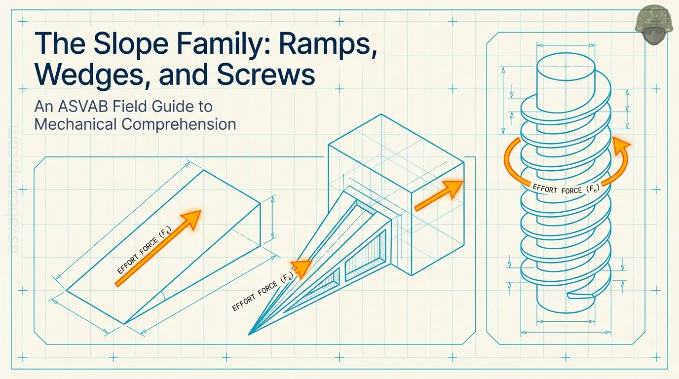
A ramp is a fixed sloped surface: the load slides or rolls up it. A wedge is a slope that moves, pushed into a gap or material so its faces spread things apart. A screw is a slope wrapped in a spiral around a shaft, so turning it drives the load along the axis. All three trade a longer effort path for a smaller effort force.
What a machine can and cannot do
A simple machine can change the size of a force, its direction, or the distance over which it acts. It cannot give you more work out than you put in. In the ideal case,
in real machines friction turns part of the input into heat, so
Any claim of getting extra energy from a ramp or screw is wrong.
Force and distance are paired quantities
Work is force times the distance moved in the direction of the force,
If a machine cuts the needed force in half, the effort must move twice as far to do the same work. Force and distance always change together in opposite directions: lower force means longer travel.
Inclined-plane geometry
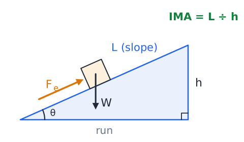
An inclined plane is described by three lengths: the vertical rise , the horizontal run, and the sloped length measured along the surface. The angle is measured between the ramp and the ground. The sloped length is always the longest side.
Why the ideal ramp ratio is L divided by h
Without friction, the work you do pushing along the ramp equals the work of lifting the load straight up:
Rearranging gives the ideal mechanical advantage.
Because is longer than , the ratio is greater than 1, so the effort is smaller than the load.
Calculating ideal effort on a ramp
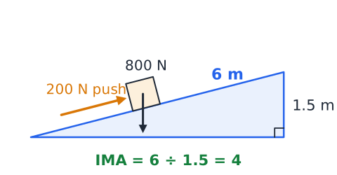
A worker pushes an 800 N cart up a ramp 6 m long that rises 1.5 m. The ideal advantage is
so the ideal effort is
Check the work:
J in and
J out.
A gentle ramp has a longer path
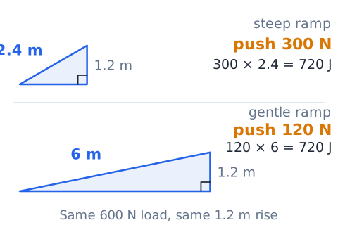
Suppose a 600 N load must rise 1.2 m. A 2.4 m ramp needs an ideal effort of 300 N, while a 6 m ramp needs only 120 N. Both cases require 720 J of work, because
The gentle ramp feels easier per step, but you walk farther to do the same job.
A steep ramp approaches direct lifting
As a ramp gets steeper, its length shrinks toward its height and approaches 1. A 1.25 m ramp rising 1.0 m has an IMA of only 1.25, so a 500 N crate needs an ideal 400 N push. At a vertical slope,
the IMA is 1 and you are simply lifting the full weight.
Ramp angle and gravitational components
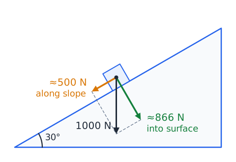
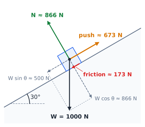
On a slope at angle , the weight splits into two parts. The part pulling down along the slope is ; the part pressing into the surface is . For a 1000 N load on a 30 degree ramp, about 500 N acts along the slope and about 866 N presses into it.
Normal force is not the load weight on an incline
The normal force is the push of the surface back on the load, at right angles to the surface. On level ground it equals the weight, but on a slope it equals , which is smaller. A 400 N box on a 20 degree incline has a normal force of about 376 N. Since friction depends on the normal force, using the full weight overstates friction.
Static versus kinetic friction
Static friction resists the start of motion; kinetic friction acts once the object slides. Static friction can rise up to , and kinetic friction is about , with usually larger. With
on level ground, it takes 250 N to break a crate loose but only 150 N to keep it sliding.
Effort moving a crate uphill with friction
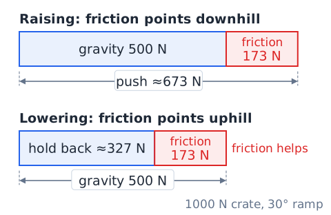
A 1000 N crate slides up a 30 degree ramp at steady speed with
The slope component is about 500 N. Friction is
and it points downhill, opposing the motion. The needed push along the slope is about
well above the frictionless value.
Why the same ramp differs downhill
Friction always opposes the motion, so its direction flips when the crate moves down. Using the same 1000 N crate and 30 degree ramp, gravity pulls about 500 N downhill while friction pushes about 173 N uphill. To lower it at steady speed, a helper must hold back only about 327 N. Friction helps when lowering and hurts when raising.
Ideal and actual advantage are different
Ideal mechanical advantage comes from geometry alone, such as for a ramp, and assumes no friction. Actual mechanical advantage comes from measured forces.
Because real effort must also overcome friction, AMA is always less than IMA for a real ramp, wedge, or screw.
Ramp efficiency from actual and ideal advantage
Efficiency compares what you get to what the geometry promises.
A ramp 5 m long rising 1 m has IMA 5. If a 900 N load actually needs 225 N, AMA is 4 and efficiency is
Input and output distances must match the path
On a ramp, the input distance is the length traveled along the slope, because that is the direction of your push. The output distance is the vertical rise, because the job is lifting against gravity. Mixing them up, such as using horizontal run for the input, gives the wrong work and the wrong advantage.
Ramp work example with losses
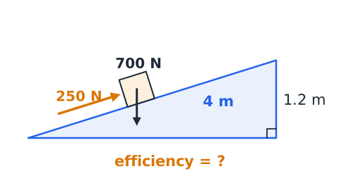
A mover pushes with 250 N along a 4 m ramp to raise a 700 N dresser 1.2 m. Input work is
Output work is
Efficiency is
and the missing 160 J became heat from friction.
Ramp geometry with a right triangle
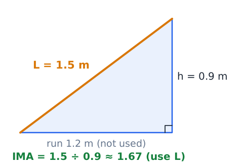
The rise, run, and slope length form a right triangle, so the Pythagorean theorem links them.
A ramp rising 0.9 m over a 1.2 m run has
Its IMA is
Use the slope length, not the run, in the ratio.
Mass and weight are not interchangeable
Mass, in kilograms, is the amount of matter. Weight, in newtons, is the pull of gravity on it,
with
A 50 kg drum weighs about 490 N. On a ramp with IMA 4, the ideal effort is about 122.5 N, not 12.5. Convert mass to weight before using force formulas.
Units and significant figures on a ramp
Use the same length unit for and so the ratio has no units. A ramp 3.2 m long rising 80 cm should be written as 3.2 m and 0.80 m, giving IMA 4, not 0.04. Round answers to match the precision of the given data; a ratio from two-digit measurements does not justify six digits.
Free-body diagrams reveal the necessary forces
A free-body diagram draws the load as a dot or box with every force acting on it. For a crate on a ramp, show weight straight down, the normal force perpendicular to the surface, friction along the surface opposing motion, and the applied push. Tilting your axes to match the slope makes it easy to see which components must balance.
Ramps in real work settings
Loading ramps on trucks, wheelchair ramps, and boat launches are all inclined planes. Accessible ramps for wheelchairs are commonly limited to a slope of about 1 unit of rise per 12 units of run, giving an IMA near 12. That gentle slope keeps the push small enough for one person, but it means the ramp must be long, often with landings to rest.
Wedge as a moving inclined surface
A wedge is an inclined plane that does the moving instead of the load. When you drive a wedge forward, its sloped faces push sideways on whatever surrounds them. A splitting maul, a doorstop, a chisel, and the tip of a nail all act this way. A small forward push over a long distance becomes a larger sideways push over a short distance.
Wedge length and thickness
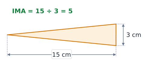
For test problems, a wedge's ideal advantage is its length divided by its thickness at the wide end.
A wedge 15 cm long and 3 cm thick at the back has IMA
Long, thin wedges give large advantages; short, fat ones give small advantages.
Why a thin wedge still travels farther
To open a gap equal to its thickness, a wedge must be driven in its full length. A thin wedge opens the gap slowly, so the effort travels a long way for each bit of spreading. That long travel is exactly why the effort can be small. A thick, blunt wedge spreads quickly but needs a much harder push.
Cutting, splitting, and fastening examples
A splitting wedge is 20 cm long and 4 cm thick, so its IMA is 5. A 300 N push on it ideally produces about 1500 N of spreading force on the log. A chisel uses the same idea to cut wood, and a nail point uses it to push fibers aside so the nail can enter.
Wedge angle and penetration
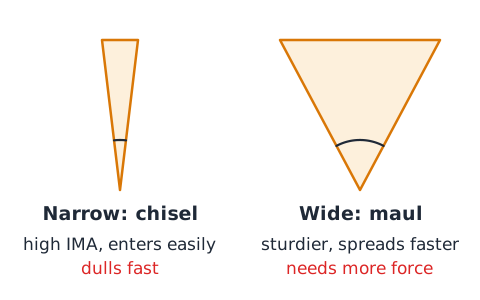
The tip angle controls how a wedge behaves. A narrow angle, like a razor or a fine chisel, gives a high advantage and enters material easily, but the thin edge dulls or chips quickly. A wider angle, like an axe or splitting maul, is sturdier and pries pieces apart faster, but it needs more force to drive in.
Wedge force illustration
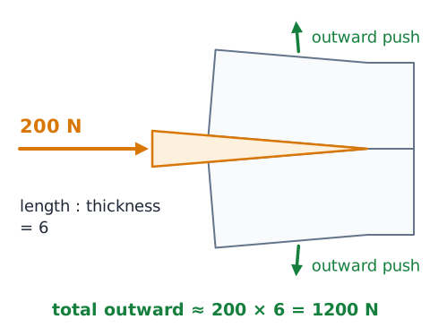
Picture a hammer striking the back of a wedge with 200 N while the wedge has a length-to-thickness ratio of 6. Ideally, the faces press outward on the material with about
N in total. The input moves a long way into the crack, and the two sides of the material move apart only a short distance.
Friction sometimes helps a wedge stay in place
Friction lowers a wedge's efficiency, but it is also why a wedge stays put. A rubber doorstop, shims under a cabinet, or a wedge holding a tool head on its handle remain wedged because friction on their faces resists sliding back out. A perfectly slippery wedge would pop out whenever the squeezing force pushed back.
Wedge geometry is model dependent
Books measure wedges slightly differently. Some use the length of a sloped face, others the straight length along the center, and some treat a double wedge as two ramps back to back. For thin wedges these give nearly the same answer. On the ASVAB, use length divided by thickness unless the question defines something else.
A screw is an inclined plane wrapped around a cylinder
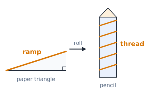
Imagine cutting a long paper triangle and rolling it around a pencil: the slanted edge spirals around like a thread. A screw thread is that ramp. Each turn of the screw slides the load a short way along the spiral slope, so the load moves along the axis while your hand moves around a much longer circular path.
Thread pitch measures adjacent thread spacing
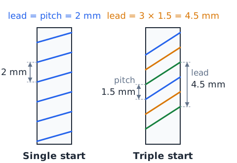
Pitch is the distance from one thread crest to the next, measured along the axis. A metric bolt might have a pitch of 1.5 mm. Inch fasteners often state threads per inch instead; 20 threads per inch means a pitch of
Lead measures travel per complete revolution
Lead is how far the screw or nut advances along the axis in one full turn. A screw can have more than one separate thread, called starts, wound side by side.
For a single-start screw, lead equals pitch.
Single-start screw calculation
A single-start clamp screw has a pitch of 2 mm, so its lead is also 2 mm. After 15 full turns, the clamp jaw advances
To advance a known distance, divide that distance by the lead: 12 mm of travel takes
Multi-start screw calculation
A triple-start screw has a pitch of 1.5 mm between neighboring crests. Its lead is
so each turn advances it 4.5 mm, and 10 turns move it 45 mm. Multi-start threads, used on items like some jar lids and pen caps, close quickly with fewer turns but give less force advantage.
Helical path distance and screw advantage
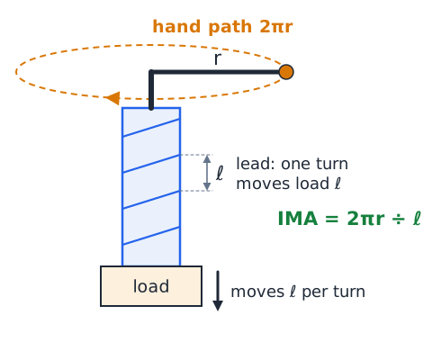
In one turn, the effort at a handle of radius moves around a circle of length , while the load moves one lead .
Use the same units for and . This ratio is usually large, often in the hundreds.
Why the handle radius matters
The handle radius sets how far your hand travels per turn. Doubling the radius doubles the circumference, which doubles the IMA and cuts the ideal effort in half. This is why a vise or screw jack uses a long bar instead of a small knob. The thread did not change; only the lever arm on the input side got longer.
Why smaller lead can multiply force
Lead appears in the denominator of the screw IMA, so a finer thread gives more advantage. Halving the lead doubles the IMA, because the load now rises only half as far per turn while your hand travels the same circle. The cost is time: a fine thread needs many more turns to move the load the same distance.
Numerical ideal screw calculation
A screw jack has a 0.25 m handle and a lead of 5 mm, or 0.005 m. The handle circle is
To raise a 10,000 N load, the ideal effort is
N at the handle end.
Rotational work uses torque and angle
Torque is a turning effect,
measured in newton-meters. When a torque turns through an angle in radians, the work done is
One full revolution is radians, so one turn delivers
This is the same work as force times the circular distance .
Load work during one screw revolution
During one turn, the axial load moves one lead, so the work done on it is . An 8000 N load on a screw with a 4 mm lead gains
J of work per revolution.
Solving ideal torque for an axial load
Setting input work equal to output work for one turn gives
For the 8000 N load and 4 mm lead,
N·m in the ideal case. Real screws need noticeably more because of thread friction.
Screw pitch is not thread diameter
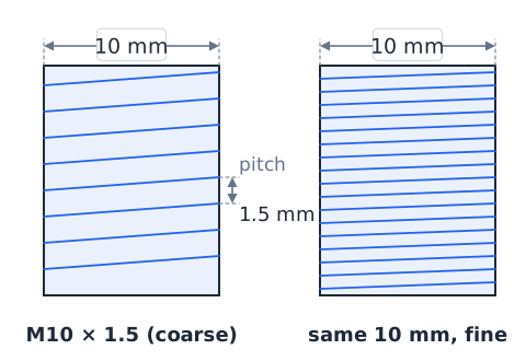
Diameter is how thick the screw is; pitch is how close the threads are. They are separate measurements. A metric bolt labeled M10 x 1.5 has a 10 mm diameter and a 1.5 mm pitch. Two bolts with the same diameter can have coarse or fine threads, and only the pitch and number of starts decide how far one turn moves the bolt.
Right-hand and left-hand threads
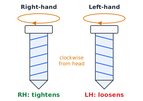
Most screws are right-hand: turning them clockwise, viewed from the head, drives them in or tightens them. Left-hand threads work the opposite way. They are used where normal rotation could loosen a right-hand part, such as the left pedal on a bicycle, or to keep some gas fittings from being mixed up. Handedness changes direction, not advantage.
Screw jack versus fastening screw
A screw jack uses a screw to lift: a long handle and a small lead create a huge IMA so a person can raise a vehicle. A fastening screw or bolt uses the same thread to clamp parts together, turning modest torque into a large pulling force along the shank. The physics is the same; the goal is lifting in one case and holding in the other.
Tapered screws and threaded fasteners
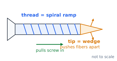
A wood screw combines two machines. Its pointed, tapered tip acts as a wedge that pushes fibers apart, and its thread acts as a spiral ramp that pulls the screw in. A machine bolt has straight threads and works with a nut; tightening the nut stretches the bolt slightly, and that stretch provides the clamping force that holds the joint.
Efficiency in screw mechanisms
Screws rub a lot of thread surface, so they are often inefficient. A screw jack with IMA 300 and a measured AMA of 90 has an efficiency of
Lubrication, smoother threads, or ball-screw designs that roll instead of slide raise efficiency, but most simple threaded screws stay well below 100%.
Irreversibility and self-locking caution
Many screws are self-locking: when you let go, the load cannot spin the screw backward because thread friction is too high. Low-efficiency screws, roughly below 50%, tend to behave this way, which is handy for a jack or a vise. Do not treat this as a guarantee. Vibration, wear, or lubrication can let a screw slip, so loads still need proper locking or support.
The difference between force, work, and power
Force is a push or pull, in newtons. Work is force times distance, in joules. Power is how fast work is done, in watts, where 1 W is 1 J per second. Pushing with 200 N over 3 m does 600 J of work; doing it in 4 s takes 150 W. A ramp lowers the force but not the work, and a slower push lowers the power.
Input effort versus output load
The effort is the force you supply at the input, such as your push on a cart or your hand on a jack handle. The load is the force the machine overcomes at the output, such as the cart's weight or the car resting on the jack. Mechanical advantage is always load divided by effort, so swapping them gives an answer less than 1 for a machine meant to help.
Choosing among the three machines
Pick a ramp when you need to raise a heavy object a moderate height and have room for a long path, such as rolling a mower into a truck. Pick a wedge to split, cut, separate, or hold something in place. Pick a screw when you need very large force, fine control, or a load that stays put, as in a vise, clamp, or jack.
Combining a ramp with a screw drive
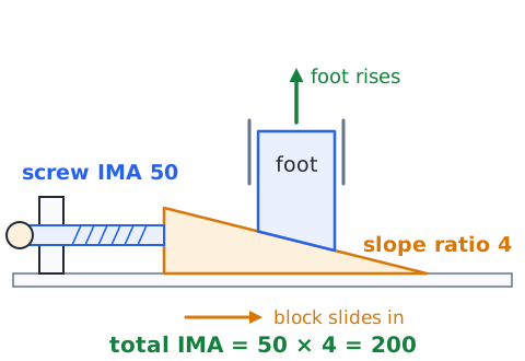
Some leveling devices use a screw to push a wedge-shaped block under a machine foot. The screw multiplies the hand force, then the sloped block multiplies it again as it lifts. Ideal advantages in series multiply. If the screw has IMA 50 and the block has a slope ratio of 4, the total ideal advantage is
Series of simple machines and total efficiency
When machines work in series, each one loses some energy, so their efficiencies multiply.
A screw stage at 60% feeding a wedge stage at 80% gives
or 48% overall. The combination is always less efficient than its weakest part.
Conservation-of-work cross-check
After any calculation, compare work in and work out. Output work must never exceed input work. If your numbers show a ramp delivering 900 J from 750 J of input, something is wrong: perhaps a unit was skipped or the run was used instead of the slope. Ideal answers give equal work; real answers give less out than in.
What happens if the load does not move
If you push on a crate resting on a ramp and it stays still, no work is done on the crate, because its distance moved is zero. Your force still matters: static friction and your push together balance the downhill pull. A jack holding a car up is in the same situation. Work and efficiency describe motion; a held load is a question of force balance.
Ideal assumptions must be stated
Ideal answers assume no friction, rigid parts that do not bend, a weightless machine, and steady motion with no speeding up. Real problems break some of these rules, and the actual effort is then larger than the ideal one. When an answer choice says ideal or frictionless, use geometry alone. When it gives friction or efficiency, adjust the effort upward.
Safety: ramps need secure support and traction
A ramp must be rated for the load, firmly supported, and hooked or blocked so its ends cannot slip. Keep the surface dry and clean so wheels and boots grip. Never stand downhill of a heavy load moving on a ramp; if it gets away, it rolls toward you. Use wheel chocks, winches, or a second person to control heavy items.
Safety: wedges and sharp edges
Wedge tools concentrate force on a small edge, so they can cut you as easily as the material. Wear eye protection when striking wedges, since chips and fragments can fly. Check that striking heads are not cracked or mushroomed, because flattened edges can break off. Cut away from your body and keep your free hand out of the path of a chisel or blade.
Safety: never rely on a lifting jack alone
A jack is made to lift, not to hold a load while someone works underneath. Its threads or seals can slip, and the vehicle can shift off the jack head. Before reaching under a raised load, set it on rated jack stands or solid blocking on firm, level ground, chock the wheels, and check that it is stable.
Common misconception: long ramp is less work
A longer ramp makes the push easier, not the work smaller. Lifting a load to a given height always needs at least of work. Adding length only spreads that work over more distance at a lower force. With friction, a very long ramp can even take slightly more total work, since friction acts over the whole length.
Common misconception: wedge creates outward force
A wedge does not make force from nothing. It redirects your forward push into sideways pushes and enlarges them because the input moves farther than the faces spread. The work out never exceeds the work in. A wedge that spreads with 5 times your force also opens the gap only one fifth as far as you drive it.
Common misconception: every screw advances one pitch
Only a single-start screw moves one pitch per turn. A double-start screw moves two pitches, and a triple-start moves three, because lead equals pitch times starts. If a question mentions multiple starts, multiply before you calculate travel, IMA, or torque. Using pitch alone would overstate the advantage of a multi-start screw.
Common misconception: bigger screw equals more travel
A thicker screw does not automatically move farther per turn. Travel per turn equals the lead, which depends on thread spacing and starts, not on diameter. A large bolt with fine threads can advance less per turn than a small screw with coarse threads. To compare travel, compare leads; to compare effort, also compare the handle radius.
Multi-step worked review: a ramp
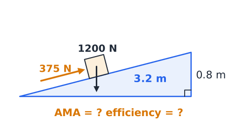
A 1200 N crate must rise 0.8 m using a 3.2 m ramp. IMA is
so ideal effort is 300 N. The measured effort is 375 N, so AMA is
Efficiency is
Check: input
output
Multi-step worked review: a screw
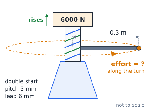
A double-start jack screw has 3 mm pitch, so its lead is 6 mm. With a 0.3 m handle, IMA is
Lifting 6000 N needs about 19.1 N ideally. Ideal torque is
N·m. At 25% efficiency, the real effort is about 76.4 N.
Final checklist for multiple-choice calculations
Before choosing an answer, ask: Did I convert mass to weight? Are lengths in the same unit? For a ramp, did I use slope length over height? For a screw, did I find lead from pitch and starts? Is my effort smaller than the load for a helping machine? Does work out stay at or below work in? Is AMA no greater than IMA? Eliminate choices that break these rules.
Summary: force travels farther to become easier
Ramps, wedges, and screws are all sloped surfaces that trade distance for force. Ramp IMA is , wedge IMA is length over thickness, and screw IMA is divided by the lead, where lead is pitch times starts. AMA uses measured forces, and efficiency is AMA over IMA. Friction makes real effort larger, can make screws self-locking, and never lets output work exceed input work. Always support raised loads safely.
 English ▾