 ASVAB Camp
Learning target and examination context
By the end of this lesson you should be able to name the common gear types and tell which kind of shaft layout each one serves: parallel, intersecting, crossed at right angles, or rotary-to-straight-line. You will predict which way each gear in a train turns, find output speed for simple, idler and compound trains, estimate output torque with and without losses, and use module and pitch diameter to size gears and rack travel. ASVAB Mechanical Comprehension items often show a gear sketch and ask about direction, speed or force.
What a driving gear means
The driving gear, or driver, is the gear that receives motion from the power source, such as an electric motor, an engine or a hand crank, and pushes on the next gear. The gear it pushes is the driven gear. In a longer train, a gear can be driven by one neighbor and drive another, so the labels describe roles. In speed formulas the driver usually gets the subscript 1 and the driven gear the subscript 2, as in and for their speeds in rpm.
Gear teeth and positive transmission
Gear teeth interlock, so one gear cannot slip past the other the way a smooth wheel can slip on a belt or on another wheel. Each tooth of the driver pushes one tooth space of the driven gear forward. This is called positive transmission: the speed relationship is fixed by the tooth counts and does not drift with load. That is why gears are chosen for clocks, transmissions and machine tools where timing must stay exact. The tradeoff is that a jammed load cannot slip, so overload can break teeth.
Pitch circle versus outside diameter
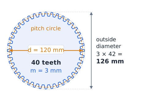
Every gear has an imaginary pitch circle where the teeth of two mating gears effectively roll against each other without sliding. Its diameter, the pitch diameter , is the size used in speed and center-distance calculations. The outside diameter, measured across the tooth tips, is a little larger, because the teeth stick out beyond the pitch circle. When a problem gives a gear size for ratio work, assume it means the pitch diameter unless it says otherwise. Mating gears touch at one shared point on their pitch circles.
Tooth number as a ratio tool
Meshing gears must have teeth of the same size, so the number of teeth is proportional to pitch diameter. A 40-tooth gear is twice as large across its pitch circle as a compatible 20-tooth gear. That lets you use tooth counts instead of diameters in ratio problems, and counts are exact whole numbers, which makes the arithmetic clean. The basic relation for one mesh is that the driver's teeth times its speed equals the driven gear's teeth times its speed.
Defined reduction ratio
The gear ratio, often written , is defined here as input speed divided by output speed. For a single mesh it equals the driven tooth count divided by the driver tooth count.
If is greater than 1, the output turns slower than the input: a speed reduction, written like 3:1. If is less than 1, the output turns faster: a speed increase. Always check which definition a question uses before you compare answers.
Simple speed reduction example
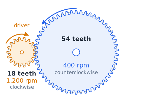
An 18-tooth pinion on a motor turns at 1,200 rpm and meshes directly with a 54-tooth gear. The ratio is
so this is a 3:1 reduction. Output speed is the input speed divided by 3.
The larger gear turns at 400 rpm, one third of the motor speed, and in the opposite direction because the two gears mesh externally.
A speed-increasing pair
Gears can also raise speed. Suppose a 60-tooth gear turning at 100 rpm drives a 25-tooth pinion. The small gear must turn more often to keep up with every tooth passing the mesh.
The ratio
is less than 1, so speed goes up while available torque goes down by the same factor. A hand-cranked drill uses this idea.
Counting turns without rpm
Some questions give revolutions instead of rpm. The logic is identical, because teeth passing the mesh must match on both gears. If a 30-tooth driver turns 8 times,
pass the contact point. A 40-tooth driven gear then turns
times. Counting the teeth that pass is a reliable check whenever you doubt which way to divide.
Tangential velocity at a mesh
At the contact point, both pitch circles move at the same surface speed, because the teeth are locked together. That surface speed is
with in revolutions per unit time. Example: a gear with a 0.1 m pitch diameter at 600 rpm (10 rev/s) has
A mating gear of 0.25 m diameter must share that speed, so it turns at
Direction of two external gears
When two gears mesh on the outside of each other, they always turn in opposite directions. Picture the teeth at the contact point: if the driver's teeth there move downward, they push the driven gear's teeth downward too, which spins the driven gear the other way around its own center. So a clockwise driver produces a counterclockwise driven gear, viewed from the same side. Size does not matter; only the external mesh does.
Three external gears in a line
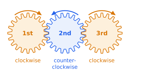
With three external gears in a row, each mesh reverses direction. If the first gear turns clockwise, the second turns counterclockwise and the third turns clockwise again. The rule generalizes: gears in odd positions (first, third, fifth) match the driver, and gears in even positions turn the opposite way. This only holds when each gear is on its own shaft and meshes with the next one in a single chain.
The purpose of an idler gear
An idler is a gear placed between the driver and the driven gear that turns freely on its own shaft and does no work on a load. It has two jobs. First, it adds a mesh, so the output turns the same direction as the input instead of the opposite one. Second, it fills a gap, allowing the input and output shafts to sit farther apart without using huge gears. It does not change the overall speed ratio between the first and last gears in the ideal model.
Idler speed-ratio derivation
Call the driver A, the idler I and the output B. Apply the single-mesh rule twice and multiply.
The idler tooth count cancels. Only the first and last gears set the speed, so you can ignore the idler's size when finding output rpm.
Idler numerical example
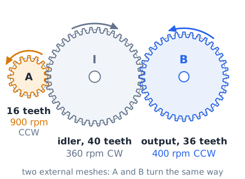
A 16-tooth driver turns counterclockwise at 900 rpm. It meshes with a 40-tooth idler, which meshes with a 36-tooth output. Skip the idler for speed:
For direction, count meshes: two external meshes, so the output turns counterclockwise, the same as the driver. The idler itself turns clockwise at 360 rpm.
Compound gears share one shaft
In a compound train, two gears of different sizes are fixed to the same shaft. Because they are locked together, they must have the same angular speed in rpm and turn in the same direction. Their tooth counts differ, so their rim speeds differ, but their rpm cannot. Moving from one of these gears to the other is not a mesh, so it neither reverses direction nor changes speed. Each true mesh in the train still reverses direction and scales speed.
Compound two-stage example
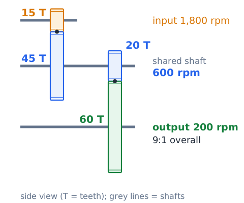
Input: a 15-tooth pinion at 1,800 rpm drives a 45-tooth gear. Fixed on that gear's shaft, a 20-tooth pinion drives a 60-tooth output gear. First stage:
The 20-tooth pinion shares the shaft, so it also turns at 600 rpm. Second stage:
The overall reduction is
a 9:1 ratio.
The correct compound-ratio workflow
Treat a compound train stage by stage. For each mesh, divide the driven count by the driver count, then multiply those stage ratios together.
Here gear 1 drives gear 2, gear 3 sits on the shaft with gear 2, and gear 3 drives gear 4. A common error is to treat gears 2 and 3 as if they meshed with each other. They do not; they share a shaft and simply carry the speed across.
Compound speed-increase example
A wind-up toy has a 72-tooth gear turning at 50 rpm that drives a 24-tooth pinion. On the pinion's shaft, a 40-tooth gear drives a 20-tooth output. Stage ratios are
so output speed is
six times faster.
Reversing versus multiplying
Keep two questions separate. Direction depends only on how many external meshes the motion passes through: an odd number reverses it, an even number keeps it. Speed depends on the tooth-count ratios of the meshes, with idlers cancelling and shared shafts adding nothing. An idler changes direction but not speed. A compound shaft changes speed through the meshes on either side of it, while the shaft itself changes neither.
Output torque in an ideal gear pair
In a frictionless gear pair, torque changes in the opposite way to speed. If the output turns slower by the ratio , its torque grows by the same ratio.
Torque is in newton-meters (N·m) or pound-feet. Example: a 3:1 reduction fed with 8 N·m gives an ideal output of 24 N·m. A speed-increasing pair does the opposite and gives less torque than it receives.
Efficiency makes an important difference
Real gears lose some energy to friction in the teeth and bearings and to churning oil. Efficiency is the fraction of input power that reaches the output, written as a decimal or percent. To include it, multiply the ideal torque by .
Example: a 5:1 reducer with 6 N·m in and 90 percent efficiency gives
N·m, not 30.
Power does not multiply
Gears trade speed for torque, but they never create power. Mechanical power in rotation is torque times angular velocity,
If a reducer cuts speed to one quarter, ideal torque goes up four times, so the product stays the same. This is why a large torque gain is not free energy: the output turns much more slowly. With losses included, output power is always somewhat less than input power, never more.
Converting rpm to angular velocity
Power calculations need angular velocity in radians per second. One revolution equals radians and one minute is 60 seconds.
Here is in rpm. For a motor at 1,500 rpm,
rad/s.
A checked power example
A motor delivers 10 N·m at 1,500 rpm, so input power is
An ideal 5:1 reducer gives 300 rpm (about 31.42 rad/s) and 50 N·m. Output power:
The powers match, which confirms the torque and speed answers.
Why more teeth usually means slower
Each revolution of a gear passes all of its teeth through the mesh. A large gear has more teeth to pass, so while a small pinion completes one full turn, the large gear completes only a fraction of a turn. That is why the bigger gear in a pair is the slow one and the smaller gear is the fast one. The rule holds whichever gear is the driver: big gear, low rpm, high torque; small gear, high rpm, low torque.
Spur gears
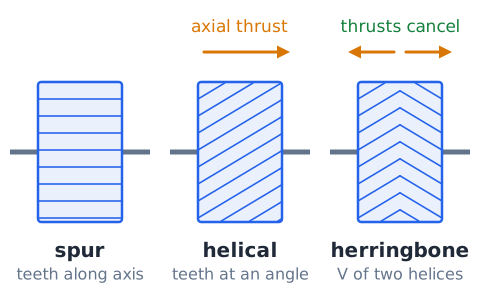
A spur gear is the simplest type: a flat wheel whose teeth are straight and run parallel to the shaft axis. Two spur gears connect parallel shafts. They are cheap to make, efficient and easy to recognize in a diagram, which is why most ASVAB gear sketches show them. Because each tooth engages along its full width at once, spur gears can be noisy at high speed, and they push only sideways on their shafts.
Bevel gears
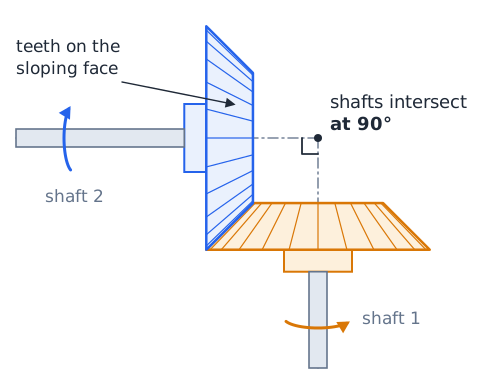
Bevel gears are shaped like cut-off cones, with teeth on the sloping face. They connect shafts whose axes intersect, most often at 90 degrees, so they can turn a drive around a corner. A hand drill uses a bevel pair to change the vertical crank motion into horizontal chuck rotation, and a vehicle differential uses bevel gears to send drive to the wheels. When two bevel gears have the same tooth count they only change direction; unequal counts also change speed, using the same tooth-count ratio as spur gears.
Helical gears
Helical gears have teeth cut at an angle to the axis, forming part of a helix. Each tooth engages gradually, starting at one end and sliding across, so more teeth share the load and the gears run quieter and smoother than spur gears. The angled teeth also push the gear along its shaft, creating axial thrust that the bearings must resist. Herringbone gears pair two opposite helices to cancel that thrust. Speed ratios still follow the tooth counts.
Worm and wheel
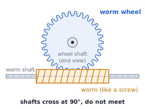
A worm looks like a screw. It meshes with a toothed worm wheel, and their shafts cross at right angles without intersecting. Each turn of the worm advances the wheel by only a tooth or two, so the set gives a very large speed reduction in a small space. Many worm sets are self-locking: the worm can turn the wheel, but the wheel cannot back-drive the worm. That feature suits hoists, gates and tuning pegs. Friction is high, so efficiency is lower than for spur gears.
Worm starts and speed ratio
The number of starts on a worm is the number of separate threads wound around it. A single-start worm moves the wheel one tooth per turn; a two-start worm moves it two teeth per turn.
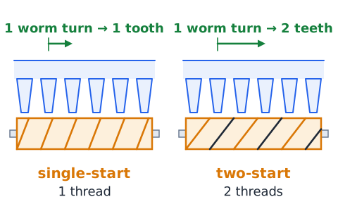
Example: a three-start worm driving a 60-tooth wheel gives
a 20:1 reduction. At 1,200 rpm on the worm, the wheel turns at 60 rpm.
Rack and pinion
A rack is a straight bar with teeth along one side. The round gear that meshes with it is called the pinion. When the pinion turns, the rack slides in a straight line, and pushing the rack would turn the pinion. This pair converts rotary motion to linear motion or the reverse. Car steering, sliding gates and the focus knob on many microscopes use racks and pinions. Turning the pinion the other way reverses the rack's travel.
Rack travel in one revolution
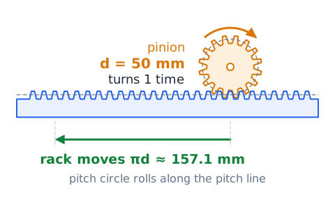
In one full turn, the pinion's pitch circle rolls out a length equal to its circumference, so the rack moves that far.
Here is rack travel and is the pinion pitch diameter, in the same length unit. A 50 mm pinion moves the rack about 157.1 mm per turn, and three turns move it about 471.2 mm.
Internal gear meshes
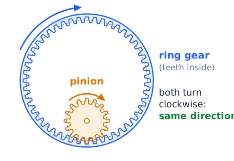
An internal gear, or ring gear, has its teeth cut on the inside of a ring. A smaller pinion meshes inside it. Unlike an external mesh, an internal mesh makes both gears turn in the same direction, because the pinion's teeth push the ring's teeth along the same way around. The speed ratio still uses tooth counts. Internal meshes are compact and carry load on more teeth at once, so they appear in planetary sets and some winches.
Planetary gear basics
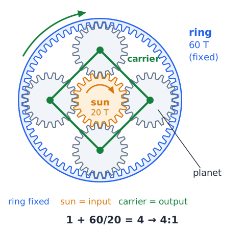
A planetary, or epicyclic, set has a central sun gear, several planet gears around it on a movable carrier, and an outer ring gear meshing with the planets. Holding one of these three members still and driving another gives different ratios. With the ring fixed, sun input and carrier output, the reduction is . A 20-tooth sun and a 60-tooth ring give
a 4:1 reduction.
Concentric shafts and planetary outputs
In a planetary set, the input and output shafts lie on the same center line, which keeps the unit compact and makes it easy to stack stages. Load is split among several planets, so a small set can carry high torque. Automatic transmissions, electric screwdrivers and wheel hubs on heavy vehicles use them. Shifting which member is held changes the ratio, and locking two members together makes the whole set turn as one at 1:1.
Gear teeth and shaft relationships
Match the gear type to the shaft layout. Spur and helical gears connect parallel shafts. Bevel gears connect intersecting shafts, usually at right angles. A worm and wheel connect shafts that cross at right angles without meeting. A rack and pinion turn rotation into straight-line motion. Two gears fixed on one shaft are a rigid compound pair with no mesh between them. Recognizing the layout from a sketch tells you which rules apply before any numbers appear.
Gears compared with belts
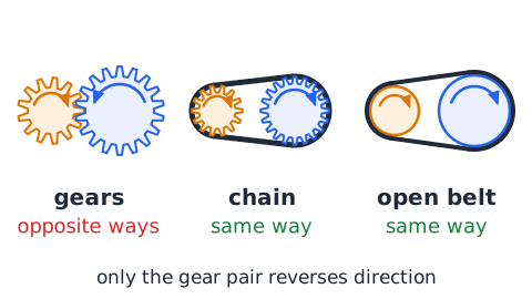
A belt drive uses smooth pulleys and friction. It is quiet, cheap, tolerant of misalignment and can span long distances, and it can slip under a sudden overload, which protects the machine. That slip also means the speed ratio is not exact. Gears give an exact ratio and handle high torque in a small space but need precise mounting and lubrication. With an open belt both pulleys turn the same way; with an external gear pair they turn opposite ways.
Difference between gears and chains
A chain drive uses toothed sprockets linked by a chain, as on a bicycle. Like gears, it gives positive transmission without slip, and its speed ratio follows the tooth counts on the sprockets. Unlike a gear pair, the two sprockets turn in the same direction and can be far apart. Chains stretch with wear and need tension adjustment and lubrication. Gears are better for compact, high-precision drives; chains suit long shaft spacing.
Backlash
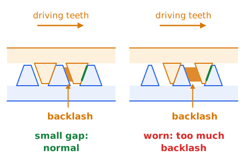
Backlash is the small gap between the back of one tooth and the face of the mating tooth. A little backlash is needed so teeth do not bind when they heat up and expand, and so oil can get between them. Too much backlash lets the output gear wobble or lag when the input reverses, which causes clunking and lost accuracy in positioning machines. Wear increases backlash over time. Precision equipment uses tight tolerances or spring-loaded split gears to reduce it.
Tooth wear and gear noise
Teeth slide and roll against each other under heavy contact pressure, so their surfaces slowly wear. Signs include pitting, polished or scuffed faces, and growing backlash. Worn or misaligned teeth strike rather than roll, producing whine, grinding or knocking. A new noise in a gearbox is often an early warning that lubrication, alignment or bearings need attention. Running gears beyond their rated load speeds up wear and can crack teeth at their roots.
Lubrication and heat
Friction at the teeth and bearings turns part of the input power into heat. Oil or grease keeps a thin film between surfaces, which cuts friction, carries heat away and slows wear. Gearboxes are often partly filled with oil so the lower teeth splash it around. Worm sets, which slide a great deal, run especially warm. Too little lubricant, or oil that is dirty or broken down, raises temperature and losses and lowers efficiency.
Bearings and support
Gear shafts ride in bearings mounted in a rigid housing. The bearings hold each shaft at the right center distance and let it spin with little friction. Mesh forces push gears apart and, with helical, bevel and worm gears, also along the shaft, so bearings must carry both kinds of load. If a shaft bends or a bearing wears, gears move out of position, mesh poorly and wear quickly. Good support is as important as good teeth.
Gear pitch compatibility
Two gears can mesh only if their teeth are the same size and shape. In metric gearing, tooth size is set by the module , the pitch diameter in millimeters per tooth.
Gears with equal modules (and the same pressure angle) can run together whatever their tooth counts. US gearing often uses diametral pitch instead, teeth per inch of pitch diameter, which is the inverse idea.
Module example
A metric spur gear has 40 teeth and a 120 mm pitch diameter. Its module is
Any gear that mates with it also needs a 3 mm module. For a standard gear the outside diameter is , so this gear measures
across its tips.
Circular pitch meaning
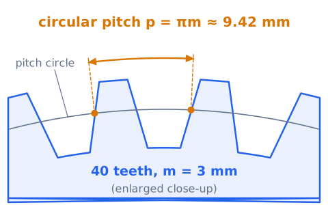
Circular pitch is the distance from one tooth to the matching point on the next tooth, measured along the pitch circle. Since the circumference is shared by teeth,
For a 3 mm module,
Mating gears must have equal circular pitch.
Center distance for a pair
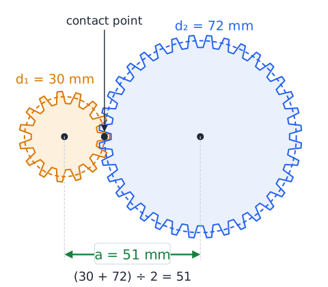
For two external gears in mesh, the pitch circles just touch, so the distance between shaft centers equals the sum of the two pitch radii.
Example: pitch diameters of 30 mm and 72 mm give
If the shafts are set closer, the teeth jam; farther apart, backlash grows and the teeth may skip.
Calculating from equal module
Because
for each gear, center distance can be written with tooth counts.
This version is handy when a problem gives tooth counts and a shared module but no diameters. Example: two mating gears with a 2.5 mm module have 20 and 44 teeth. Add the teeth, multiply by the module and halve:
As a check, the pitch diameters are 50 mm and 110 mm, and half their sum is also 80 mm.
Wheel size and mechanical advantage
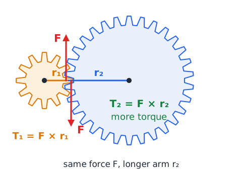
A gear acts like a lever whose arm is its pitch radius. The force at the teeth is the same on both gears of a pair, but the larger gear applies that force at a longer radius, so it produces more torque. This is why the larger driven gear in a reduction gives a mechanical advantage. The ideal mechanical advantage of the pair equals the ratio of the output radius to the input radius, which matches the tooth ratio.
Real and ideal machines
An ideal machine has no friction, so output work equals input work and torque rises exactly as speed falls. A real gearbox loses some energy, so actual mechanical advantage is lower than ideal. The speed ratio, however, stays exactly as the teeth set it, because teeth cannot slip. In a problem, use the ideal values unless an efficiency is given, then reduce the torque, not the speed, by that efficiency.
Direction with more than one mesh
For any fixed-axis train, count only the external meshes between the input and the gear you care about. Odd count: opposite direction from the input. Even count: same direction. Shared-shaft steps add nothing to the count, and an internal mesh does not reverse. For example, a train with an input mesh, a compound shaft and a second mesh has two external meshes, so the output turns the same way as the input.
Gear-train diagram strategy
When a diagram appears, work in a fixed order. First mark the driver and trace the path to the output. Next label each gear's rotation with a small arrow, flipping at every external mesh and keeping it across any shared shaft. Then list each mesh as driven over driver and multiply for the overall ratio, skipping idlers. Finally check that the answer is sensible: a big output gear should be slower than a small input gear.
Working with exact fractions
Keep ratios as fractions until the last step to avoid rounding error. Example: 1,000 rpm passes through meshes of 12 to 28 teeth and 15 to 45 teeth.
That simplifies to
Cancelling first is faster and safer than multiplying decimals.
Worked example: direct pair
Problem: a 22-tooth driver turns clockwise at 660 rpm and meshes with a 55-tooth gear. Find the output speed and direction.
Step 1: speed,
Step 2: one external mesh, so the output turns counterclockwise. Answer: 264 rpm counterclockwise.
Worked example: an idler arrangement
Problem: a 25-tooth input at 480 rpm counterclockwise drives a 30-tooth idler, which drives a 60-tooth output.
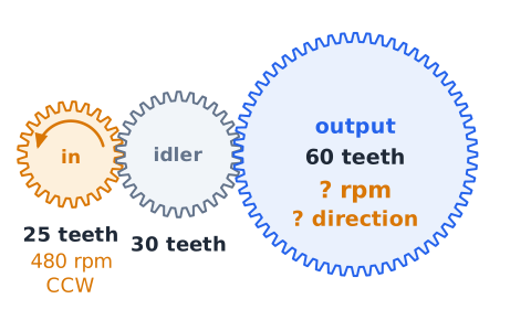
Speed: the idler cancels, so
Direction: two external meshes, so the output also turns counterclockwise. Answer: 200 rpm counterclockwise.
Worked example: compound direction
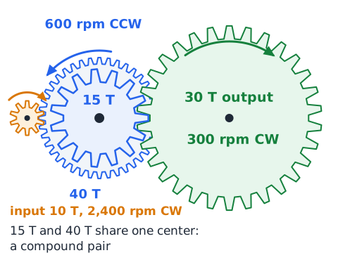
A 10-tooth input turning clockwise at 2,400 rpm drives a 40-tooth gear. A 15-tooth gear on that shaft drives a 30-tooth output. The middle shaft turns counterclockwise at
The output:
clockwise after the second mesh.
Worked example: efficiency adjustment
Problem: a 6:1 reducer receives 4 N·m and is 85 percent efficient. Find the output torque.
Ideal torque is
N·m. Losses reduce it:
N·m. The output speed is still one sixth of the input speed, since efficiency affects torque, not the tooth ratio.
Worked example: missing tooth count
Problem: a 24-tooth driver runs at 750 rpm, and the driven gear must turn at 450 rpm. How many teeth does it need?
Use
The driven gear needs 40 teeth. Check:
Worked example: motor and load
Problem: a conveyor needs 120 rpm, and the motor runs at 1,800 rpm. Find the total ratio and a two-stage way to get it.
Ratio:
so 15:1. Split as : a 15-tooth pinion driving a 45-tooth gear, then a 12-tooth pinion on that shaft driving a 60-tooth gear. Check:
Selecting a reduction ratio
Designers often pick a ratio to meet a torque target. Suppose a motor gives 2 N·m and a winch drum needs at least 14 N·m, with a gearbox that is 90 percent efficient. Solve for the ratio:
Since 7.8 is the minimum, choose the next practical ratio, 8:1, which gives
N·m. The drum then turns at one eighth of motor speed.
Equal-size meshing gears
When two meshing external gears have the same number of teeth, the ratio is 1:1. The output turns at exactly the input speed, and the ideal torque is unchanged. The only effect is a reversal of direction. For instance, two 30-tooth gears with the input at 500 rpm clockwise give 500 rpm counterclockwise at the output. Equal gears are used to reverse rotation or to drive two shafts in step, as in some pumps.
A fixed gear does not transmit freely
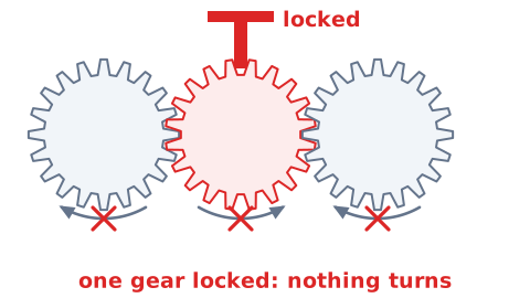
If any gear in a simple train is locked so it cannot turn, every gear meshed with it is also locked, and nothing turns. Questions sometimes show a held gear to test this. The exception is a planetary set, where holding one member is exactly how the set produces a ratio, because the other members can still move around it. In an ordinary fixed-axis train, a stuck gear stops the whole chain and puts high stress on its teeth.
Torque direction versus rotation direction
Torque and rotation are related but not identical. The driver's torque pushes the driven gear in the direction it turns. The driven gear pushes back on the driver with a reaction torque, which the motor must overcome. A gearbox housing must also be bolted down, because the input and output torques do not balance (they add when the shafts turn in opposite directions and subtract when they turn the same way), and the leftover torque tries to spin the housing. On the exam, rotation direction follows the mesh rules, while torque size follows the ratio and efficiency.
Gear train mechanical advantage
The overall mechanical advantage of a gear train is the product of the stage ratios, not their sum. A 4:1 stage followed by a 3:1 stage gives a 12:1 train. Ideal output torque is 12 times input torque, and output speed is one twelfth of input speed. Stacking stages lets designers reach large ratios with moderate gear sizes, which is why many motors drive their loads through two or three stages rather than one huge gear.
Axes and viewing conventions
Clockwise and counterclockwise only make sense from a chosen viewpoint. A gear that looks clockwise from the front looks counterclockwise from the back. In diagrams, assume all directions are seen from the same side unless told otherwise. With bevel or worm gears the shafts point different ways, so describe direction relative to each shaft's own viewing side, or by which way the teeth move at the mesh. Stay consistent throughout a problem.
Spotting impossible answers
Many wrong choices can be removed without full arithmetic. In a reduction, output speed must be lower than input speed, and ideal torque must be higher. An idler cannot change the overall speed. A real efficiency below 100 percent cannot raise torque above the ideal value. A choice with both higher speed and higher torque at the output violates energy conservation. Eliminate these first, then calculate to pick among the rest.
Reading gear diagrams at test speed
Under time pressure, do direction questions by counting meshes, not by tracing every tooth. For speed, find the first and last gears, check whether any gears share a shaft, and write a quick fraction product. Look for gears drawn touching rather than overlapping: touching rims usually mean a mesh, while gears drawn on one center are a compound pair. Don't trust drawn sizes if tooth counts are given; the numbers win.
Quick diagnostic drill
A 10-tooth gear drives a 30-tooth gear at an input of 450 rpm. What is the output speed? Answer:
Four external gears sit in a row and the first turns clockwise. Which way does the fourth turn? Answer: counterclockwise, after three meshes.
A two-start worm drives a 30-tooth wheel. What is the ratio? Answer:
a 15:1 reduction.
A 4 mm module gear has 25 teeth. What is its pitch diameter? Answer:
Formula and concept review
Single mesh:
Compound train: multiply stage ratios,
idlers cancel.
Torque:
with
for an ideal train.
Power:
Worm:
Rack:
per turn.
Sizing:
Final examination checklist
Identify the gear types and shaft layout first. Count external meshes for direction: odd reverses, even keeps. Gears on a shared shaft have the same rpm and direction. Find speed from tooth counts, multiplying stage ratios and ignoring idlers. Torque rises as speed falls, then multiply by efficiency if one is given. Power never increases through gears. For worms divide wheel teeth by starts; for racks use per turn. Finally, reject answers that break these rules.
 English ▾