 ASVAB Camp
Learning objectives and exam boundaries
In this lesson you will learn to tell hydraulic systems from pneumatic ones, calculate pressure as force over area, apply Pascal's principle to connected pistons, relate piston travel to area and find cylinder speed from flow rate. You will use Boyle's law for compressed air and recognize the job of pumps, valves, regulators and cylinders. Safety topics stay general: why stored fluid energy must be controlled. Mechanical Comprehension questions use simple ideal models, not detailed repair procedures.
Hydraulic versus pneumatic power
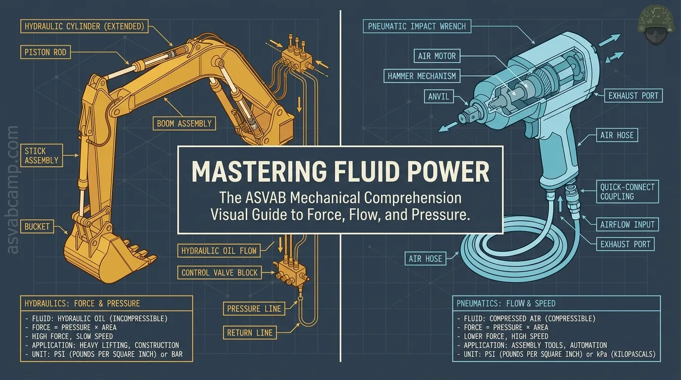
Both hydraulic and pneumatic systems move energy through a fluid in pipes or hoses to push pistons or turn motors. Hydraulics uses a liquid, usually oil, which barely compresses, so it gives firm, precise motion and very high forces, as in excavators and car lifts. Pneumatics uses compressed air, which squeezes easily, so it is springier and works at lower force but is fast, clean and cheap, as in shop air tools and packaging machines.
Pressure is force divided by area
Pressure tells you how concentrated a force is over a surface:
With force in newtons and area in square meters, pressure is in pascals (Pa). A 600 N force pressing evenly on 0.020 square meters gives
The same force on a smaller area gives a higher pressure.
Pressure units and conversions
One pascal is one newton per square meter, a small amount, so kilopascals (kPa) are common. Useful links:
Normal air pressure at sea level is about 101 kPa, or about 14.7 psi, and 1 psi is roughly 6.9 kPa. So 250 kPa equals 2.5 bar.
Gauge versus absolute pressure
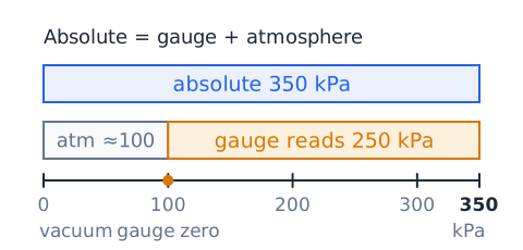
Most pressure gauges read zero when open to the air, so they show gauge pressure: how far above atmospheric the fluid is. Absolute pressure counts from a perfect vacuum:
Taking the atmosphere as about 100 kPa, a tire gauge reading 250 kPa means about 350 kPa absolute. Gas-law calculations must use absolute pressure.
Pascal principle: transmitted pressure change
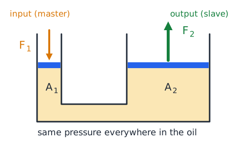
Pascal's principle says that a change in pressure applied to a confined fluid at rest is passed on undiminished to every part of the fluid and to the walls of its container. If you push a small piston and raise the pressure by 200 kPa, the pressure everywhere in the connected, sealed fluid rises by 200 kPa, including under a large piston far away.
Hydraulic master and slave pistons
In a hydraulic system, a small input piston (often called the master) pushes fluid to a larger output piston (the slave). Because the pressure is the same on both,
The output force grows by the ratio of the areas. That area ratio is the ideal mechanical advantage of the system.
Worked force multiplication example
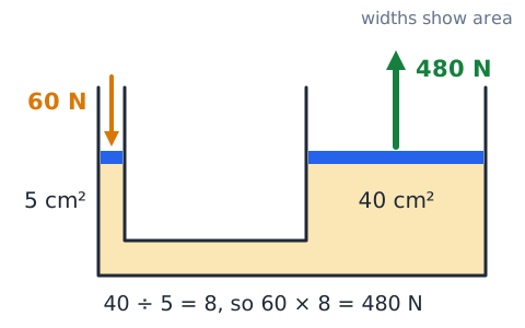
An ideal lift has a 5 square centimeter input piston and a 40 square centimeter output piston. A 60 N push is applied to the input.
The output piston pushes with 480 N.
Diameter is not piston area
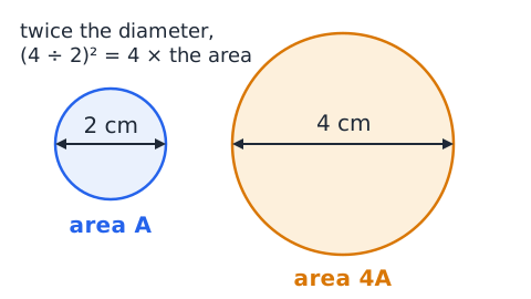
Pistons are circles, and area grows with the square of the diameter:
Double the diameter and the area becomes four times as large. A 4 cm piston compared with a 2 cm piston has an area ratio of
not 2. Square the diameter ratio before using it.
Volume conservation in an ideal lift
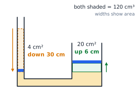
A liquid does not compress, so the volume pushed out of the small cylinder equals the volume that enters the large one:
A 4 square centimeter piston moving 30 cm displaces 120 cubic centimeters. Spread under a 20 square centimeter piston, that volume lifts it
Work and mechanical advantage
A hydraulic press multiplies force but not work. With an area ratio of 5, a 60 N push through 0.30 m gives
The output pushes 300 N but moves only 0.06 m:
Force went up five times; distance went down five times.
Why real hydraulics are not perfect
Real systems fall short of the ideal. Seals rub against cylinder walls and create friction. Fluid flowing through hoses, fittings and valves loses pressure to internal friction. Small leaks let some fluid bypass a piston. Oil compresses very slightly and hoses swell under pressure, so some input motion is absorbed. Trapped air makes this worse. As a result, measured output force and travel are a little less than calculated.
Hydraulic reservoir and pump roles
The reservoir, or tank, stores the oil the system needs, lets heat escape and gives trapped air and dirt time to separate out. The pump draws oil from the reservoir and pushes it into the system. A key idea: a pump creates flow, not pressure. Pressure builds only when that flow meets resistance, such as a load on a cylinder. With nothing resisting, the oil simply circulates at low pressure.
Positive-displacement pump concept
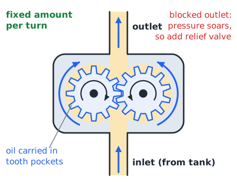
Most hydraulic pumps are positive-displacement types, such as gear, vane or piston pumps. Each turn of the shaft traps a fixed amount of oil and forces it out the outlet, so output flow depends mainly on shaft speed, not on the load. Because the pump keeps forcing oil whether or not it has somewhere to go, a blocked outlet can drive pressure extremely high. That is why these systems need a relief valve.
Hydraulic pressure relief valves
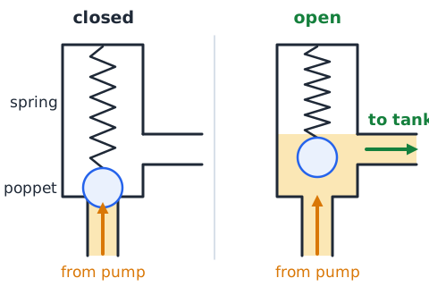
A pressure relief valve sets the maximum pressure a hydraulic circuit can reach. A spring holds the valve closed. When pressure pushes hard enough to overcome the spring, the valve opens and sends oil back to the tank, so pressure stops rising. This protects the pump, hoses and cylinders from bursting when a cylinder hits the end of its stroke or the load jams.
Check valve versus directional valve
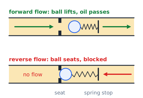
A check valve lets fluid flow in one direction only; reverse flow pushes it shut. It is used to hold a load in place or keep oil from draining back. A directional control valve chooses where flow goes, for example sending oil to one end of a cylinder to extend it or to the other end to retract it, often controlled by a lever, a solenoid or an air signal.
Flow controls change speed
A flow control valve uses an adjustable restriction to limit how much oil reaches an actuator each second. Since a cylinder's speed is
where Q is flow rate and A is piston area, cutting the flow slows the piston. It does not change the area, and in an ideal model it does not change the force available at full pressure.
Flow rate is volume per time
Flow rate measures how much fluid passes a point each second or minute:
If 12 L of oil passes in 30 s, then
which is 24 L per minute. Watch the time units.
Continuity through a narrowing line
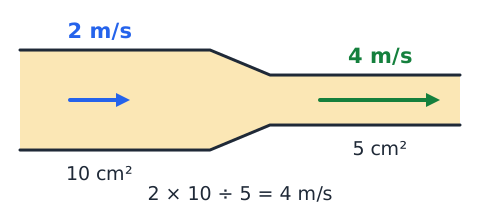
For a steady flow of liquid, the same volume per second must pass every section of a pipe:
If oil moves at 2 m/s in a 10 square centimeter line that narrows to 5 square centimeters, then
Smaller area means faster flow.
Hydraulic cylinder extension rate
A cylinder extends as fast as oil fills it. Divide the flow rate by the piston area. With 200 cubic centimeters per second flowing into a cylinder whose piston area is 40 square centimeters,
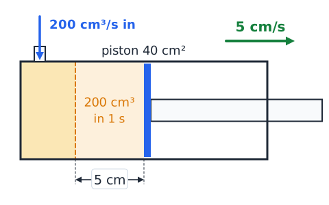
A bigger piston at the same flow moves more slowly.
Hydrostatic pressure with depth
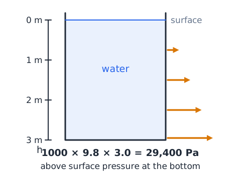
Pressure in a still liquid increases with depth because of the weight of liquid above:
Here is density in kg per cubic meter, g is about 9.8 m/s squared and h is depth in meters. In water 3.0 m deep,
About 29 kPa above surface pressure.
Open and closed hydraulic circuits
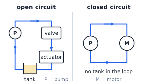
In an open circuit, oil returns from the actuators to a reservoir at about atmospheric pressure, and the pump draws fresh oil from that tank. Most machinery uses this simple layout. In a closed circuit, oil returning from a hydraulic motor goes straight back to the pump inlet without passing through the tank, which suits some vehicle drives. Either way, the oil itself is reused, not used up.
Single-acting cylinders
A single-acting cylinder has fluid power on one side of the piston only. Pressurized fluid extends the rod; a spring, the weight of the load or another outside force returns it when the fluid is allowed to drain. A simple bottle jack is an example: pumping lifts the ram, and opening the release valve lets the weight push the oil back to the reservoir.
Double-acting cylinders
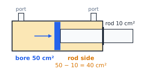
A double-acting cylinder has ports at both ends, so fluid can push the piston both ways. On the rod side, the rod takes up part of the piston face:
With a 50 square centimeter bore and a 10 square centimeter rod, the rod side has 40 square centimeters. At equal pressure, retracting gives less force, and at equal flow it moves faster than extending.
Hydraulic motor versus cylinder
A hydraulic cylinder produces straight-line motion: its rod pushes or pulls through a fixed stroke. A hydraulic motor produces continuous rotation: pressurized oil flowing through it turns a shaft, much like a pump run in reverse. Pressure sets the torque the motor can deliver, and flow rate sets how fast it spins. Motors drive tracks, winches and conveyors; cylinders lift, press and clamp.
Hydraulic brakes as an application
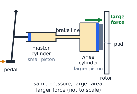
Vehicle brakes use hydraulics. Pressing the pedal pushes a piston in the master cylinder, raising pressure in the brake fluid. That pressure travels through lines to larger pistons at each wheel, which press the pads or shoes against rotors or drums with a much larger force. Because brake fluid barely compresses, the pedal feels firm. Air in the lines makes it feel spongy and reduces braking.
Hydraulic lifts and jacks
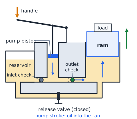
A hydraulic jack has a small pump piston worked by a handle and a large lifting ram. Each stroke forces a small amount of oil past a check valve into the ram cylinder, raising the ram a little, and the check valve keeps the oil from flowing back. Many short strokes add up to lift a car. A release valve lets the oil return to the reservoir to lower the load slowly.
Fluid viscosity and temperature
Viscosity is a fluid's resistance to flowing, its thickness. Hydraulic oil gets thicker when cold and thinner when hot. Cold, thick oil makes pumps work harder and actuators move sluggishly. Hot, thin oil leaks more easily past seals and gives less protective film between moving parts. That is why manufacturers specify an oil grade and an operating temperature range, and why some systems use coolers or heaters.
Filters and contamination
Dirt, metal particles and water are leading causes of hydraulic failures. Tiny particles wear pumps and valves, and clog small passages. Filters in the suction, pressure or return lines trap contaminants. As a filter fills with dirt, it restricts flow more, raising the pressure drop across it. Many filters have an indicator or bypass. Clean oil, sealed reservoirs and regular filter changes keep a system reliable.
Leak versus trapped air symptoms
Different faults show different signs. An external leak shows up as oil on the machine or floor and a falling reservoir level. An internal leak, such as past a worn piston seal, may let a cylinder slowly drift under load with no visible oil. Trapped air tends to cause spongy, jerky motion, foamy oil and noisy pumps. Neither cause should be assumed from a single symptom.
What pneumatics uses
Pneumatic systems use compressed air, or sometimes another gas such as nitrogen, as the working fluid. Air is free, does not need a return line because it vents to the atmosphere after use, and a small leak does not create an oily mess. Because air compresses, pneumatic actuators are quick but less precise in position under changing loads. Typical uses include impact wrenches, nail guns, paint sprayers, door openers on buses and pick-and-place machines on assembly lines.
Air compressors and stored energy
A compressor draws in outside air and squeezes it into a smaller volume, raising its pressure. The compressed air is stored in a tank called a receiver, which smooths demand and lets the compressor rest between cycles. That stored air holds a lot of energy. Even with the compressor turned off, a full receiver can drive tools or burst a hose.
Air preparation components
Air from a compressor carries moisture, dirt and sometimes oil. Before it reaches tools and valves, it usually passes through an air preparation unit. A filter removes particles and liquid water. A regulator sets a steady working pressure. In some systems, a lubricator adds a fine oil mist for tools that need it. This trio is often abbreviated FRL, for filter, regulator, lubricator.
Pressure regulator purpose
A pressure regulator keeps the downstream pressure at a chosen setting even when the supply pressure from the receiver rises and falls. Lowering the setting reduces actuator force and saves air; raising it, within ratings, gives more force. A regulator cannot make pressure higher than its supply.
Directional air valves
Directional valves route compressed air to one side of a cylinder and open the other side to exhaust. They are described by ports and positions, such as a 5/2 valve with five ports and two positions. They may be shifted by hand, by a solenoid or by an air signal, and springs often return them.
Pneumatic cylinders and return springs
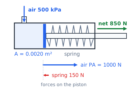
A single-acting air cylinder often uses an internal spring to retract. When air enters, it must overcome that spring as well as the load, so the useful output is
At 500 kPa on 0.0020 square meters, air gives 1000 N; with a 150 N spring, about 850 N remains.
Air pressure and an ideal force
The force a pneumatic cylinder can push equals gauge pressure times piston area. With 600 kPa gauge on a 0.0025 square meter piston,
Convert kPa to Pa before multiplying.
Boyle law at constant temperature
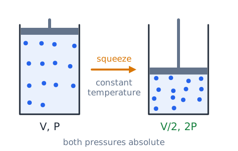
For a fixed amount of gas held at constant temperature, pressure and volume are inversely related:
Halve the volume and the pressure doubles. Both pressures must be absolute, not gauge. Any volume unit works as long as both match.
Boyle-law worked example
Air at 100 kPa absolute fills 12 L and is squeezed slowly to 3 L.
That is absolute pressure. With an atmosphere of about 100 kPa, a gauge would read about 300 kPa.
Temperature affects compressed gas
In a sealed, rigid tank, warming the gas raises its pressure:
Temperatures must be in kelvin and pressures absolute. A tank at 400 kPa absolute and 280 K, warmed to 308 K, reaches
Compressed air is not an ideal liquid
Hydraulic formulas assume an incompressible fluid. Air is not. When a pneumatic cylinder meets a load, the air inside compresses a little before the piston moves, and if the load changes, the piston position shifts. That springiness cushions shocks but makes holding a precise position hard. Air also heats when squeezed and cools when it expands, so simple Boyle-law answers are estimates.
Air flow and actuator speed
How quickly a pneumatic cylinder moves depends mainly on how fast air can flow in and out. Narrow hoses, small valves and restricted exhausts slow it down. Flow control valves on the exhaust side are a common way to set speed smoothly. Raising pressure helps somewhat, but the springy air makes speed less predictable than in hydraulics.
Energy tradeoffs in pneumatics
Compressed air is convenient but expensive to make. Compressing air heats it, and most of that heat is lost as the air cools in the receiver and lines. Leaks waste energy continuously, even when no tools run. Overall, only a small fraction of the electricity driving a compressor ends up as useful work at the tool. Fixing leaks and lowering pressure to what the job needs save energy.
Pressure times area applies to both media
The force rule is the same for oil and air:
A hydraulic cylinder at 10 MPa and an air cylinder at 0.6 MPa use the same formula. Hydraulics usually wins on force because it runs at much higher pressure, not because the physics differs. Use consistent units: Pa with square meters gives newtons.
Pressure and flow solve different problems
Pressure and flow answer different questions. Pressure, times area, decides how much force an actuator can push with. Flow rate, divided by area, decides how fast it moves. A cylinder that is strong enough but slow needs more flow, not necessarily more pressure. A cylinder that moves quickly but stalls under load needs more pressure or a larger piston.
Why equal piston pressure is not equal force
Two pistons on the same fluid see the same pressure, but larger area means larger force. At 300 kPa,
Four times the area gives four times the force.
Equivalent area units
Area units convert by the square of the length factor. Since 1 m equals 100 cm,
So 35 square centimeters equals 0.0035 square meters. Dividing by 100 instead of 10,000 is a common error.
The cylinder displacement calculation
The volume of fluid a cylinder takes in during a stroke is
where A is piston area and s is stroke length. A 20 square centimeter piston moving 15 cm needs
That is 0.30 L.
Pressure drop through restrictions
When fluid flows through a narrow spot, such as a partly closed valve, a clogged filter, a kinked hose or a small fitting, it loses pressure across that restriction. The more restrictive the passage or the higher the flow, the bigger the pressure drop. That lost pressure turns into heat. With no flow, the pressure on both sides of a restriction evens out.
Hydraulic accumulators
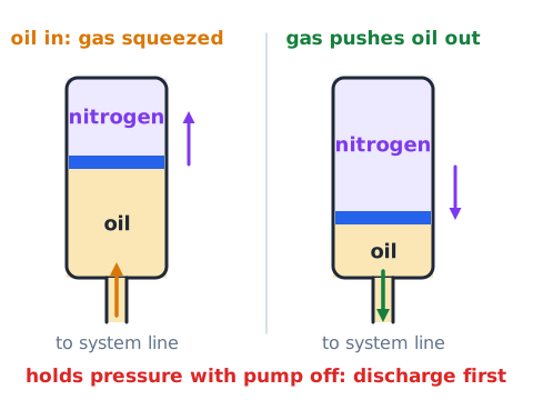
An accumulator stores hydraulic energy by pushing oil against a compressed gas charge, usually nitrogen, or a spring. It can supply bursts of flow, smooth pressure pulses and provide emergency power. Because it holds pressure even when the pump is off, an accumulator must be safely discharged before work on the system.
Pneumatic exhaust and mufflers
After air has pushed a piston, the directional valve releases it to the atmosphere through an exhaust port. That rapid release is loud. Mufflers, also called silencers, are fitted to exhaust ports to reduce noise, and some include restrictors to adjust speed.
Hydraulic return and tank line
After oil has done its work in an actuator, it must go back to the reservoir through the return, or tank, line. This line runs at low pressure. A blocked return line can stop an actuator or raise pressure where it is not expected.
Pressure gauge placement
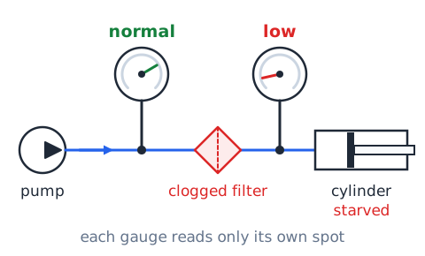
A pressure gauge reports the pressure only where it is connected. A gauge at the pump outlet can read normal while a clogged filter or valve downstream starves the cylinder. Technicians often compare readings at several points to locate a restriction. A gauge measures pressure, not flow or speed.
Symptoms require several hypotheses
A single symptom can come from several causes. A slow cylinder might mean low pump flow, a partly closed flow control, an internal leak past a seal, thick cold oil or a clogged filter. Weak force might come from low pressure, a misadjusted relief valve or a leak. Good troubleshooting lists possible causes, then checks them with measurements.
Never use skin to seek leaks
Never run your hand along a hose to find a leak. A pinhole jet of hydraulic oil can pierce skin and inject fluid under it. The wound may look small but can cause severe tissue damage and needs emergency medical care. Compressed air jets can also break skin. Use cardboard or another tool to locate leaks with the system safely depressurized when possible.
Hazardous energy isolation
Fluid power systems can move unexpectedly even when the motor is off. Accumulators, raised loads, compressed air in receivers and trapped pressure in lines all store energy. Before maintenance, authorized workers follow lockout and tagout procedures: shut down, isolate energy sources, release or block stored pressure, support raised loads, and verify that nothing can move before work begins.
Compressed air cleaning restrictions
Compressed air can blow dust and chips off parts, but it is not a toy. Workplace rules limit the pressure of air used for cleaning and require guarding and eye protection. Never point an air nozzle at yourself or anyone else, or use it to dust off clothing or skin. Air forced into the body can cause serious injury.
Eye and hose hazards
Air or oil jets can throw chips and dust into eyes, so safety glasses are standard. A hose that comes loose under pressure can whip violently and strike people. Use rated fittings and restraints, depressurize before disconnecting, and inspect hoses for cracks, bulges or wear.
Pressure rating is a hard limit
Every hose, fitting, cylinder and tank has a maximum working pressure set by its manufacturer. Exceeding it can cause a sudden burst, flying parts or a high-pressure jet. Do not substitute lower-rated parts or raise relief valve settings to get more force. If more force is needed, the correct fix is a larger piston or a system designed for higher pressure, not overloading existing parts.
Reading a basic hydraulic diagram
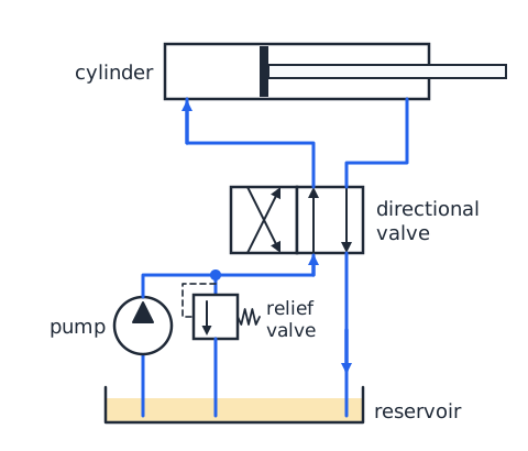
Hydraulic circuits are drawn with standard symbols. A circle with a filled triangle shows a pump; an open-topped box near the bottom is the reservoir. Rectangles divided into squares are directional valves, with arrows showing flow paths. A long rectangle with a piston line is a cylinder. Trace flow from pump through valves to the cylinder and back to tank.
Reading a basic pneumatic diagram
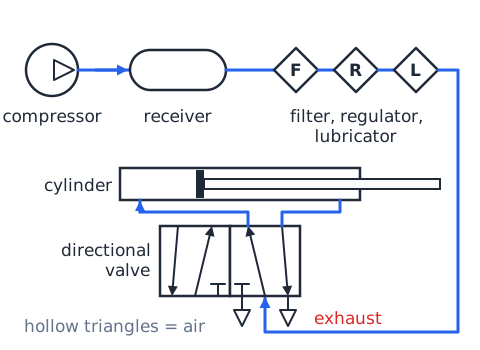
Pneumatic symbols look much like hydraulic ones, but the triangles in pumps, compressors and motors are drawn hollow to show air instead of filled for liquid. A compressor feeds a receiver, then a filter, regulator and lubricator. A directional valve sends air to a cylinder. Exhaust ports point to atmosphere, often marked with a small triangle or a muffler symbol.
Worked comparison: force versus travel
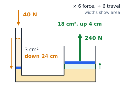
An ideal press has a 3 square centimeter input piston and an 18 square centimeter output piston. A 40 N input force gives
If the input moves 24 cm, the output moves
Six times the force, one sixth the travel.
Worked comparison: pipe velocity
A pump delivers 0.60 L/s, which is 600 cubic centimeters per second, through a line of 3.0 square centimeters. The fluid speed is
That is 2.0 m/s. In a 6.0 square centimeter line the same flow would move at 1.0 m/s.
Worked comparison: air spring
A sealed air spring holds 6.0 L at 200 kPa absolute. A load squeezes it slowly to 4.0 L. By Boyle's law,
Squeezing further keeps raising the pressure, so the spring stiffens.
Common ASVAB traps
Watch for these traps. Pressure is the same throughout a connected fluid, but force is not; bigger pistons push harder. Bigger pistons also move less and more slowly. Using diameters as areas understates the ratio; square them. Gas laws need absolute pressure and kelvin temperatures. Mismatched area units cause factor-of-10,000 errors. No hydraulic system creates energy; force gain always costs travel.
Final recap and independent practice
Pressure is force per area. Pascal's principle spreads a pressure change through a confined fluid, so output force grows with the area ratio while travel shrinks by the same ratio. Speed equals flow divided by area. Air obeys Boyle's law, and its pressure rises when it is heated in a sealed tank. Pumps create flow; relief valves cap pressure; check valves allow one-way flow; regulators set air pressure. Practice: a 2 square centimeter piston pushed with 30 N drives a 10 square centimeter piston. Output force? Answer: 150 N. If the small piston moves 15 cm, the large one moves 3 cm.
 English ▾