 ASVAB Camp

Learning goals and scope
By the end of this lesson you should be able to recognize a series circuit from its single unbranched path, add resistances to find the total, find the common current with Ohm's law, and split the source voltage into individual drops. You will also predict what opens and shorts do, place meters correctly in principle, and compute resistor power. All circuits here are ideal DC models.
Where this lesson fits on the ASVAB
Series circuits are one of the most frequent topics in ASVAB Electronics Information, and basic electricity can also appear in General Science items. Typical questions ask for total resistance, loop current, the voltage across one resistor, or what happens when a bulb burns out. They build directly on Ohm's law and the power formulas from earlier lessons, and they set up the parallel circuits that come next.
What makes a circuit complete
Steady current needs a closed loop: a source such as a battery, conductors, and at least one load, connected so charge can leave one source terminal, travel through the load, and return to the other terminal. Break the loop anywhere, with an open switch, a loose wire or a burned-out filament, and the steady current stops. A flashlight works only when the switch closes the path between battery, bulb and case.
Circuit symbols are not photographs
A schematic uses standard symbols, not pictures of the parts. A battery is drawn as long and short parallel lines, a resistor as a zigzag or small rectangle, a switch as a hinged line, and wires as straight lines. The drawing shows how parts connect, not where they sit, how big they are or what color they are. Two resistors drawn far apart may be in series, and two drawn side by side may not be.
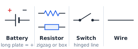
Trace one unbranched path
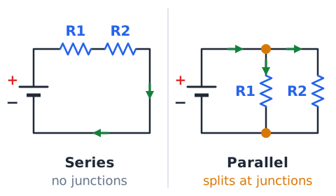
The figure shows a low-voltage ideal DC series circuit. To confirm it is series, put a finger on the positive terminal of the source and trace the wire. You pass through each component one after another and return to the negative terminal without ever reaching a fork. No junction offers charge a choice of route. That single unbranched path is the definition of series: every component is in line with every other, like beads on one string.
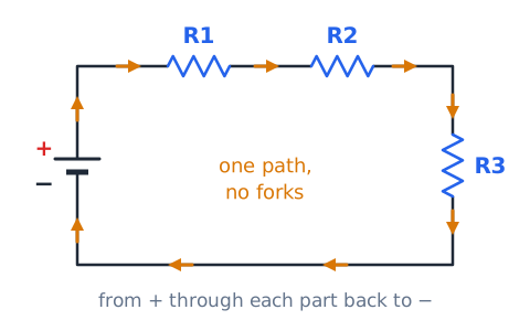
Conventional current and electrons
By convention, current is drawn flowing from the positive terminal of the source, through the circuit, and back to the negative terminal. In metal wires the actual moving charges are electrons, which drift the opposite way, from negative to positive. Both descriptions give the same answers for current size, voltage drops and power. ASVAB questions may use either; just be consistent within a problem.
Charge conservation in a series path
Charge is not created or destroyed in a resistor, and in steady DC it does not pile up anywhere. So the charge passing any point each second must equal the charge passing every other point:
Here is the total or source current and , , are the currents through each resistor. A resistor reduces voltage, not the current flowing out of it.
Current is measured in amperes
Current is the rate of charge flow, measured in amperes (A). One ampere is one coulomb of charge passing a point each second. Small electronics often use milliamperes (mA): 1 mA is 0.001 A, so 250 mA equals 0.25 A. In a series circuit there is only one current value to find, and once you know it, you know the current everywhere in the loop.
Potential difference and energy per charge
Voltage, or potential difference, is energy per unit of charge, measured in volts (V); 1 V equals 1 J per coulomb. A source raises the energy of charge passing through it, and each resistor lowers it again as the energy turns to heat or light. The amount lost across a component is its voltage drop. A 9 V battery gives each coulomb 9 J, and the resistors in the loop together take all 9 J back out.
Ohm’s law for each resistor
Ohm's law applies to each resistor using that resistor's own values:
is the drop across resistor n in volts, I is the series current in amperes, and is its resistance in ohms (Ω). With 0.5 A through a 20 Ω resistor, its drop is 10 V. Use the full source voltage only with the total resistance.
Total series resistance adds
Charge must pass through every resistor in turn, so their opposition adds:
is the total or equivalent resistance in ohms. Resistors of 10 Ω, 22 Ω and 68 Ω in series total 100 Ω. The total is always larger than the largest single resistor.
Why adding a series resistor changes current
For a fixed source voltage, the loop current is
where is the source voltage. Adding another resistor raises , so the current falls. A 24 V source with 8 Ω gives 3 A; add a 4 Ω resistor, becomes 12 Ω and current drops to 2 A. Every existing resistor now carries less current.
Series voltage-drop rule
The voltage drops across the resistors in a series loop add up to the source voltage:
This follows from energy conservation: the energy each coulomb gains in the source equals what it loses in the loads. With a 12 V source and drops of 3 V and 4 V, the third resistor must drop 5 V.
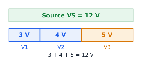
The largest resistor has the largest drop
Since every resistor carries the same current, each drop is proportional to its resistance. The biggest resistor gets the biggest share of the source voltage and the smallest gets the least. In a loop with 1 kΩ and 9 kΩ resistors, the 9 kΩ part drops nine times as much voltage as the 1 kΩ part, taking 90 percent of the source.
Voltage-divider relationship
You can find one drop directly from the source voltage:
The drop equals the source voltage times that resistor's fraction of the total resistance. For a 15 V source with 10 Ω and 20 Ω in series, the 20 Ω resistor drops
Same resistance means equal voltage drops
Equal resistors carrying equal current must have equal drops. With n identical resistors in series, each gets exactly 1/n of the source voltage. Four identical lamps on 24 V get 6 V each. This only holds when the resistances match; the symbol size or position in the drawing has nothing to do with it.
Current stays equal as voltage drops accumulate
Moving around the loop, the voltage relative to the negative terminal falls step by step at each resistor, but the current is the same at every point. Think of a water pipe going down a staircase of waterwheels: pressure drops at each wheel, but the flow rate past every point is identical. Losing voltage does not mean losing current.
A complete problem-solving sequence
Most series problems follow the same chain. First add the resistances to get . Then find the current with
Next find each drop with
Last, check that the drops add to the source voltage.
For 9 V across 1 Ω and 2 Ω:
I = 3 A, drops 3 V and 6 V, which sum to 9 V.
Units in series-circuit calculations
Ohm's law works directly when you use volts, amperes and ohms together. Mixing prefixed units without converting gives answers off by factors of 1,000. Before multiplying or dividing, rewrite milliamperes as amperes and kilohms as ohms, or else use matched pairs consistently, such as volts with milliamperes and kilohms.
Convert milliamperes before multiplying
To convert milliamperes to amperes, divide by 1,000: 40 mA is 0.04 A. Then 0.04 A through 150 Ω drops
Multiplying 40 by 150 without converting would give 6,000, a clearly impossible answer for a small circuit.
Convert kiloohms carefully
One kilohm (kΩ) is 1,000 Ω, so 4.7 kΩ is 4,700 Ω. A 9 V source across a 4.7 kΩ and a 4.3 kΩ resistor in series sees 9 kΩ total, giving
or 1 mA. A handy shortcut: volts divided by kilohms gives milliamperes.
Series circuits and power
Since all series resistors share the same current,
is the most convenient power formula:
The power in each resistor is proportional to its resistance, so the largest resistor also dissipates the most power. With 2 A through 1 Ω and 4 Ω, the powers are 4 W and 16 W. You can also use or , as long as you use that resistor's own drop, not the source voltage. The fraction of total power in any resistor equals its fraction of the total resistance.
Power conservation check
In an ideal loop, source power equals the sum of the resistor powers:
For 6 V driving 1 Ω and 2 Ω, I = 2 A. The resistors dissipate 4 W and 8 W, totaling 12 W, which matches
What happens when an ideal switch opens
An open switch puts a gap in the only path, which works like an infinite resistance. The steady current becomes zero everywhere in the loop at once, not just after the switch. With no current, every resistor drops 0 V, and the full source voltage appears across the open switch contacts. Every lamp in the series string goes dark together.
What happens when an ideal switch closes
An ideal closed switch acts like a plain wire with zero resistance and zero voltage drop. It completes the loop, so current flows at the value set by the source voltage and the total resistance. The switch itself adds nothing to , so the current is the same as if the switch were simply a wire.
Open filament or broken connection
A burned-out bulb, a blown fuse, a cracked solder joint or a disconnected wire all create an open. In a series circuit, any single open stops the current through every component. This is why older strings of holiday lights went completely dark when one bulb failed. An ideal voltmeter across the open part reads the full source voltage, while every intact resistor reads 0 V, which helps locate the fault.
Short circuit is not the same as an open
Using the figure, imagine two different faults. An open is a break: resistance becomes huge and current stops. A short is an unintended low-resistance path, such as a stray wire connecting across a component: resistance drops and current rises. In a series circuit, shorting one resistor removes it from , so the remaining resistors get more current and larger drops. Opens stop current; shorts increase it.
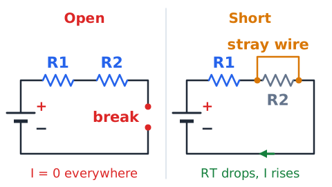
A resistor bypassed by a wire
If an ideal wire connects the two ends of one resistor, the current takes the zero-resistance wire and the bypassed resistor carries no current and drops 0 V. The circuit behaves as if that resistor were gone. Example: 10 V across 2 Ω and 3 Ω gives 2 A. Bypass the 3 Ω resistor and becomes 2 Ω, so current rises to 5 A, and the 2 Ω resistor now drops the full 10 V and dissipates 50 W instead of 8 W.
Shorting a source is unsafe
Connecting a conductor straight across a battery or supply terminals leaves almost nothing to limit current. Real batteries can then deliver very large currents that heat wires red-hot, melt insulation, cause burns or fires, and make some battery types vent or explode. Even a small battery shorted by keys or coins in a pocket can get dangerously hot. In exam diagrams this is a theoretical idea; in real life, never do it.
Voltage at nodes versus voltage across elements
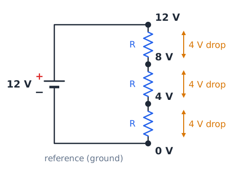
A node is a connection point. Voltage at a node is measured relative to a chosen reference, usually the negative terminal called ground. Voltage across an element is the difference between the node voltages at its two ends. With 12 V driving three equal resistors, the node voltages from the top are 12 V, 8 V, 4 V and 0 V. Each resistor has a 4 V drop across it, even though the node voltages differ.
Kirchhoff’s loop rule for a single series loop
Kirchhoff's voltage law says the voltage rises and drops around any closed loop add to zero. For one source and several resistors in series:
That is the same as saying the drops sum to the source voltage. A 20 V source with drops of 4 V, 6 V and 10 V satisfies
Junction rule distinguishes series and parallel
Kirchhoff's current law says the current entering a junction equals the current leaving it. In a true series path there are no junctions where the path splits, so the current never divides and is the same everywhere. If you see a point where three or more wires meet and the current can split, the parts beyond it are not all in series. Finding junctions is the quickest topology test.
Equal versus unequal currents: diagnostic clue
In a correctly modeled series loop, every ammeter reading must match. If two readings in one unbranched path differ, something is wrong: a meter error, a misread scale, a hidden branch, or a circuit that is not actually series. Unequal currents through two elements prove they are not in a single series path. Equal currents alone do not prove series, since identical parallel branches also carry equal currents.
An ammeter belongs in the current path
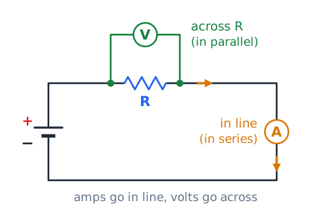
An ammeter measures the current flowing through it, so the circuit must be opened and the meter inserted in series, making the current pass through the meter. An ideal ammeter has nearly zero resistance and does not change the current. In a series circuit you can insert it at any point and read the same value. Placing an ammeter across a component or a source puts a near short there, which can blow its fuse or damage it.
A voltmeter measures a drop in parallel
A voltmeter measures the potential difference between two points, so its leads go across the component, in parallel with it, without breaking the circuit. An ideal voltmeter has very high resistance and draws almost no current. Across one resistor it reads that resistor's drop. Across the source it reads the source voltage. Across two series resistors together it reads the sum of their drops.
Distinguish a current probe from a voltage probe
Memory aid: amps go in line, volts go across. An ammeter is part of the loop, so current must travel through it. A voltmeter touches two points and compares them. On a schematic, an ammeter symbol (A in a circle) sits in the wire path, while a voltmeter symbol (V in a circle) connects to both ends of the part being measured, side by side with it.
Real batteries and internal resistance
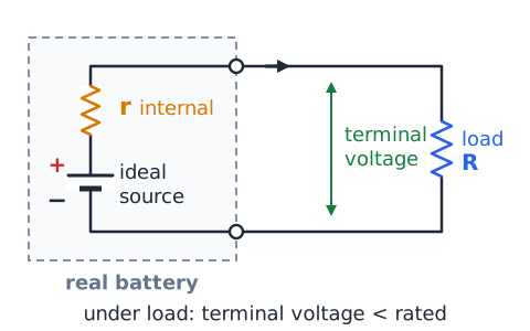
A real battery behaves like an ideal source in series with a small internal resistance. When current flows, part of the source voltage drops inside the battery, so the terminal voltage falls below its rated value. A battery that reads 9 V with no load may read less under a heavy load. Internal resistance also limits short-circuit current somewhat. ASVAB problems call sources "ideal" when this effect should be ignored.
Real wires, contacts, and resistance
Real wires, switch contacts and connectors have small resistances that sit in series with the load. Normally these are tiny, but a long thin extension cord or a corroded battery clip adds noticeable resistance. That extra series resistance drops some voltage and lowers the current, so the load gets less than full voltage and the bad connection may get hot. Ideal-circuit problems treat all wires as zero resistance.
Series lamp brightness is not purely current
In a series string, every lamp carries the same current, yet the lamps may glow differently. Brightness depends on power, and with equal current, power equals , so the lamp with greater resistance dissipates more and usually glows brighter. A filament's resistance also rises as it heats, so lamp brightness in real circuits is not perfectly predictable. Equal current does not guarantee equal brightness.
Effect of removing a series load
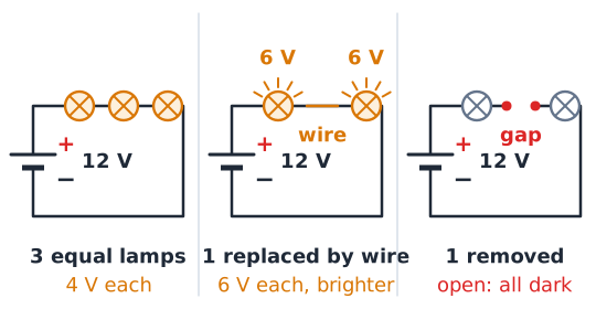
In a series circuit, physically removing a load and leaving a gap creates an open, so all current stops. Replacing that load with a plain wire is different: total resistance falls, and the current through the remaining loads rises. With three equal lamps on 12 V, each gets 4 V. Replace one lamp with a wire and the other two get 6 V each and glow brighter.
Effect of increasing only one resistor
Raising one resistor's value increases total resistance, so the loop current falls. Every other resistor then has a smaller drop. The resistor that grew takes a larger share of the source voltage, because its fraction of the total resistance increased. Example: 12 V across 3 Ω and 3 Ω gives 6 V each; change one to 9 Ω and current falls from 2 A to 1 A, with drops of 3 V and 9 V.
Equal resistors: simple fractions
With identical resistors, think in fractions. For n equal resistors in series:
If one resistor is then replaced by one twice as large, the shares follow the resistance ratio. For three equal resistors with one of them doubled, the shares are 1, 1 and 2 out of 4.
Solving backward from a measured drop
If you know one resistor's value and its voltage drop, you know the current for the whole loop:
From there you can find the total resistance, other drops or the source voltage. Suppose a 15 Ω resistor drops 3 V. The current everywhere is 0.2 A.
Finding an unknown resistance from drops
In series, the ratio of drops equals the ratio of resistances:
If a known 10 Ω resistor drops 4 V and the unknown drops 6 V, then
Finding a missing drop from the source
When the source voltage and all but one drop are known, subtract: the missing drop equals the source minus the sum of the known drops. A 48 V supply with drops of 12 V, 20 V and an unknown leaves 16 V for the last one. No resistance values are needed at all.
Choosing a formula by what is unknown
Pick your tool from the unknown. Total resistance: add the resistors. Loop current: source voltage divided by total resistance, or any one resistor's drop divided by its resistance. One drop: current times that resistance, or the divider formula. Missing drop: subtract known drops from the source. Unknown resistance: find current first, then divide its drop by the current. Power: for each resistor.
Using proportional reasoning to avoid arithmetic traps
Ratios often give the answer faster than finding the current. In a series pair of 5 Ω and 15 Ω, the drops split 1:3, so the larger takes three-quarters of any source voltage. On 40 V, that is 30 V and 10 V. Power splits in the same 1:3 ratio because the current is common. Skipping the current step removes one chance for error.
A numerical reasonableness checklist
Before choosing an answer, run quick checks. Total resistance must exceed the largest single resistor. No drop can exceed the source voltage. The drops must sum to the source. The largest resistor must have the largest drop and largest power. Current must be the same everywhere. If the circuit uses kilohms, the current is probably in milliamperes. Any answer failing these checks is wrong.
Schematic orientation and current direction
A diagram can be rotated, flipped or redrawn with wires bent at odd angles, and the circuit is unchanged as long as the connections stay the same. Turning the page does not change any current or voltage. Likewise, whether you call current clockwise or counterclockwise, the size of the current is the same. If you assume the wrong direction, the math simply gives a negative sign.
Series resistors contrasted with parallel resistors
Series and parallel follow opposite rules. In series, current is common, resistances add and voltage divides. In parallel, voltage is common, currents add and the total resistance is less than the smallest branch. A series total of 3 Ω and 6 Ω is 9 Ω; in parallel the same pair gives 2 Ω. Using the reciprocal formula on a series circuit is a common wrong answer choice.
Voltage divider loading is a limitation
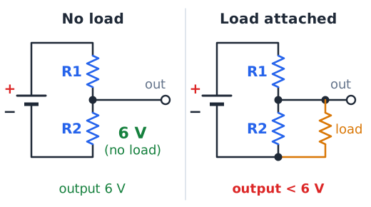
A pair of series resistors makes a handy voltage divider, but the formula assumes nothing else draws current from the middle point. Connect a load across one resistor and that load sits in parallel with it, lowering the effective resistance there and pulling the output voltage down. A divider giving 6 V with no load may give noticeably less with a load attached. That is why dividers suit reference voltages, not power supplies.
A series fuse is a protective component
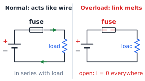
A fuse is a thin metal link placed in series with the circuit it protects. Under normal current it acts like a wire. If current exceeds its rating for long enough, the link melts and opens the circuit, stopping current everywhere in that path. A circuit breaker does the same job and can be reset. The fuse must be in series; a fuse wired in parallel would protect nothing.
Safety and exam-only modeling
The ideal circuits in this lesson are math models. Actual circuits, especially household AC, can cause shock, burns and fires. Never test by shorting a source, bypassing a fuse or touching live conductors. Measurements on real equipment belong to trained people using rated meters and proper procedures. On the exam, phrases like "theoretical" or "ideal" signal a thought experiment, not a hands-on instruction.
ASVAB reading strategy: find topology first
Before using any formula, decide how the parts are connected. Trace the path from one source terminal to the other. If there are no branches, it is series and the current is common. If the path splits, at least part is parallel. Note the given values and their units, and underline what is asked. Many wrong answers come from applying the right formula to the wrong topology.
ASVAB calculation strategy: one reliable chain
Use a consistent chain for every series problem: add resistances, find current, then find drops or power. Write the intermediate results down. When a shortcut like the divider ratio is faster, use it, but confirm the drops sum to the source. A single dependable routine is faster under time pressure than inventing a method each time.
ASVAB distractors: addition, division, and units
Wrong choices are often built from predictable slips. One adds voltage and resistance as if they were the same quantity. Another divides resistance by voltage instead of the other way around. Another uses the parallel reciprocal formula on series resistors. Another forgets to convert milliamperes or kilohms, giving answers 1,000 times too large or small. Spot the slip and the choice disappears.
ASVAB distractors: voltage and current mixups
Other traps confuse what is shared. A choice may split current among series resistors as if it divided, or give every resistor the full source voltage. Another may assign the biggest drop to the smallest resistor. Remember the pattern: in series the current is shared by all, while the voltage is shared out among them in proportion to resistance.
Summary of the three essential series laws
Three rules solve almost every ideal series circuit.
Current is the same everywhere, resistances add, and drops add up to the source voltage. Combine them with Ohm's law,
applied to the whole loop or to one resistor at a time.
Worked example — Add three resistor values
Resistors of 47 Ω, 33 Ω and 120 Ω are wired in series. Find the total resistance.
The total is 200 Ω, larger than the largest single resistor, 120 Ω, as it must be.
Worked example — Find the current from a 12 V source
An ideal 12 V battery drives 5 Ω and 15 Ω resistors in series. Find the current.
Total resistance:
The current is 0.6 A through both resistors.
Worked example — Find an unequal voltage divider
An ideal 36 V source drives 4 Ω and 14 Ω in series. Find each drop.
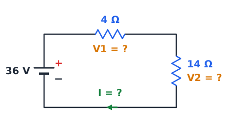
Total: 18 Ω, so I = 2 A.
Check:
The larger resistor takes the larger drop.
Worked example — Three equal resistors share voltage
An ideal 27 V source drives three 6 Ω resistors in series. Find the current and each drop.
Each drop:
which is one-third of 27 V. Check: three drops of 9 V total 27 V.
Worked example — Recover missing resistor drop
A 24 V ideal source feeds four series resistors. Three drops measure 5 V, 7 V and 3.5 V. Find the fourth.
The fourth resistor drops 8.5 V.
Worked example — Backward current from one resistor
In a series loop, a 25 Ω resistor drops 5 V. A second resistor is 35 Ω. Find the current and the source voltage.
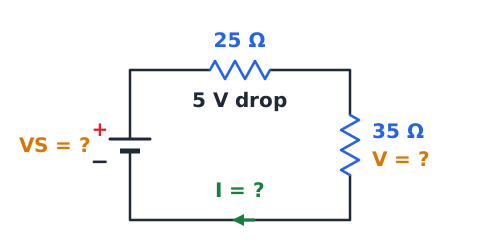
Total resistance: 60 Ω. Source:
The second resistor drops 7 V, and
Worked example — Milliampere conversion
A loop carries 15 mA through a 220 Ω resistor. Find the drop.
Convert: 15 mA = 0.015 A.
The drop is 3.3 V. Without converting, you would get 3,300 V, an absurd value.
Worked example — Kiloohm conversion
An ideal 10 V source drives 2.2 kΩ and 2.8 kΩ in series. Find the current.
Total: 5 kΩ = 5,000 Ω.
The current is 2 mA. Shortcut: 10 V divided by 5 kΩ gives 2 mA.
Worked example — Compute total resistor power
An ideal 30 V source drives 4 Ω and 6 Ω in series. Find each power and the total.
Current:
Total 90 W, matching
Worked example — Series resistor added to fixed source
An ideal 18 V source first drives a single 6 Ω resistor. Then a 3 Ω resistor is added in series. Compare current and the 6 Ω resistor's drop before and after.
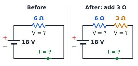
Before:
and the 6 Ω resistor drops the full 18 V.
After:
so
The 6 Ω resistor now drops
V and the 3 Ω drops 6 V. Adding resistance cut the current by one-third and took voltage away from the original resistor.
Worked example — Opening the only switch
An ideal 9 V source, a closed switch, a 1 Ω and a 2 Ω resistor form a series loop. Find the current with the switch closed, then open.
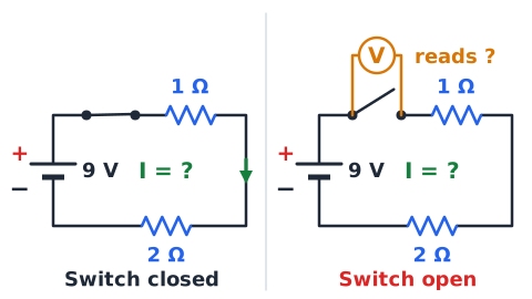
Closed:
Drops are 3 V and 6 V.
Open: the path is broken, so I = 0 A everywhere. Each resistor drops
and by the loop rule the full 9 V appears across the open switch contacts.
Worked example — Theoretical bypass of one resistor
On paper, an ideal 20 V source drives 2 Ω and 8 Ω resistors in series. An ideal wire is then drawn across the 8 Ω resistor. Find the current before and after.
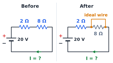
Before:
so I = 2 A. Drops are 4 V and 16 V.
After: the 8 Ω resistor is bypassed, so
Current rises fivefold, and the 2 Ω resistor now drops all 20 V. This is a thought experiment only.
Worked example — Use the voltage-divider shortcut
An ideal 50 V source drives 30 Ω and 70 Ω in series. Find the drop across the 70 Ω resistor without finding current first.
The 70 Ω resistor drops 35 V, leaving 15 V for the 30 Ω.
Worked example — Use the loop rule to catch errors
A student finds that a 14 V ideal source drives 3 Ω and 4 Ω in series at 2 A, and reports drops of 6 V and 10 V. Check the work.
Loop rule:
which is not 14 V. Recalculate:
not 10 V. Corrected drops are 6 V and 8 V, summing to 14 V.
Drill — recognize the topology
Is the arrangement series?
A battery, a switch and three lamps in one loop with no forks? Answer: yes, series.
Two resistors connected across the same two nodes? Answer: no, that is parallel.
Two parts drawn next to each other on the page? Answer: not enough information; trace the wires.
Drill — sums and units
Find the total resistance.
100 Ω, 220 Ω and 680 Ω? Answer: 1,000 Ω, or 1 kΩ.
1.5 kΩ and 500 Ω? Answer: 2 kΩ.
Four 25 Ω resistors? Answer: 100 Ω.
Current from 6 V across 3 kΩ total? Answer: 2 mA.
Drill — voltage drops
Find the requested drop.
10 V, two equal resistors, each drop? Answer: 5 V.
8 V across 1 Ω and 3 Ω, drop on 3 Ω? Answer: 6 V.
Source 30 V, drops 12 V and 10 V, third drop? Answer: 8 V.
Drill — use a known drop
A 4 Ω resistor drops 8 V in a series loop. Current? Answer: 2 A.
That loop also has a 6 Ω resistor. Its drop? Answer: 12 V.
Source voltage, if those are the only two? Answer: 20 V.
A 5 Ω resistor drops 2 V; a second resistor drops 6 V. Its value? Answer: 15 Ω.
Drill — open versus short
Predict the result in an ideal series loop.
A lamp filament breaks. Answer: all current stops and every lamp goes out.
A wire is placed across one of three equal resistors. Answer: current increases by half, and the other two drops grow.
The only switch opens. Answer: zero current; full source voltage across the switch.
A fuse blows. Answer: the circuit opens.
Drill — power and consistency
A 2 A loop current flows through 5 Ω. Power? Answer: 20 W.
A 10 V source drives 2 Ω and 3 Ω. Total power? Answer: 2 A, so 20 W.
In that loop, which resistor dissipates more? Answer: the 3 Ω, 12 W versus 8 W.
Common trap — dividing current among series loads
The mistake: assuming current splits among series resistors, so a 6 A loop with three resistors gives 2 A each. That reasoning belongs to parallel branches. In series there is only one path, so all 6 A flows through each resistor in turn. The fix: in series, divide voltage among the resistors, never the current. Every resistor carries the full loop current.
Common trap — using full battery voltage on each resistor
The mistake: applying the full source voltage to one series resistor, such as computing 12 V divided by 4 Ω when the 4 Ω resistor shares a loop with others. That gives too much current. The fix: use the source voltage only with the total resistance. For one resistor, use its own drop, found from the loop current or the divider ratio.
Common trap — confusing an open with a bypass
The mistake: treating a wire across a resistor as if it stopped current, or a broken resistor as if it raised current. These are opposites. An open, from a broken part, blown fuse or open switch, removes the path and the current falls to zero. A bypass, or short across a part, removes that part's resistance and the current rises. The fix: ask whether the change breaks the path or offers an easier path.
Quick reference and final check
In an ideal series circuit, one current flows through every part, resistances add, and drops sum to the source.
Bigger resistors take bigger drops and more power. Adding resistance lowers current. An open stops all current; a short across one part raises it. Ammeters go in series, voltmeters across. Final check: the drops add to the source voltage.
 English ▾