 ASVAB Camp
Lesson objectives and model boundary
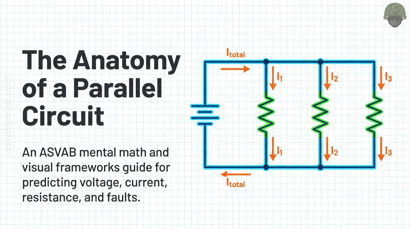
By the end of this lesson you should be able to spot resistors that share the same two nodes, explain why every branch of a parallel group sees the same voltage, and find branch currents, total current, equivalent resistance and power.
You will also predict what happens when a branch opens, when a wire shorts the rails, and when a series resistor feeds a parallel group. Throughout, the source is an ideal DC supply with a fixed voltage, wires have zero resistance, and resistors keep a constant value. Real batteries and hot filaments only approximately follow these rules.
How parallel circuits appear on the ASVAB
Electronics Information items on parallel circuits are usually short. You might be shown a schematic and asked for total resistance, told a supply voltage and asked for one branch current, or asked what happens when a lamp burns out in a house wiring setup.
Most questions reward two ideas: every branch across the same two points gets the same voltage, and the branch currents add up to the source current. Numbers are usually chosen to divide cleanly, so if your arithmetic turns messy, recheck how you read the diagram before grinding through decimals.
Recognize a junction and a branch
A junction, also called a node, is any point where three or more conductors meet. All wire attached to that point without a component in between belongs to the same node.
A branch is a single path between two junctions. Current that reaches a junction must pick one of the paths leaving it. In a two-lamp porch light, for example, the feed wire splits at one junction, runs through each lamp separately, and rejoins at a second junction.
Same two nodes is the defining test
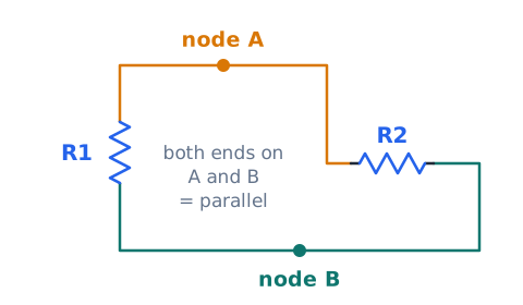
Two components are in parallel when one end of each touches node A and the other end of each touches node B. It does not matter how far apart they are drawn, whether they look alike, or whether their resistances are equal.
Trace the wire from each terminal. If you can slide along bare conductor from the left end of resistor 1 to the left end of resistor 2 without passing through anything, and the same is true on the right ends, the pair is parallel. If one resistor lies between them on the way, they are not.
Read the parallel schematic
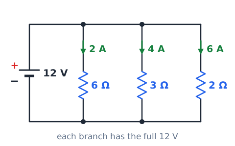
The figure shows an ideal 12 V battery with its top and bottom wires acting as two long rails. Three resistors, 6 Ω, 3 Ω and 2 Ω, each stretch from the top rail to the bottom rail.
Because all three touch the same two rails, each one has the full 12 V across it. Dividing 12 V by each resistance gives the labeled branch currents of 2 A, 4 A and 6 A. Notice the smallest resistor carries the largest current.
Node potential and equal branch voltage
Every point on an ideal wire is at one electric potential, so an entire node can be treated as a single voltage value. If the top rail sits at 9 V and the bottom rail at 0 V, any part connected between them has a difference of exactly
That is why parallel branches always share one voltage. A branch cannot have more or less than the difference between the two nodes it touches, regardless of what it contains.
Current divides rather than voltage
In series circuits the source voltage is split up among the parts. In parallel the roles reverse: the voltage is shared in full and the current is what gets split. If the source delivers , then
A good picture is a water main feeding several garden hoses at once. Each hose sees the same pressure, but the total flow in the main is the sum of the hose flows. A wider hose, like a lower resistance, takes a larger share.
Ohm’s law applies within each branch
Ohm's law,
works on any single resistor as long as you use that resistor's own voltage, current and resistance. In a parallel branch the voltage is simply the supply voltage, so
Example: a 10 V supply across a 5 Ω branch gives
A in that branch. You can solve each branch on its own without knowing anything about the others.
Equivalent resistance replaces the network
The equivalent resistance is the single resistor that would draw the same total current from the same source as the whole parallel group. Once you know it, the source sees just one load:
For instance, if a 6 V supply pushes 3 A into a network, the network behaves like
The source cannot tell whether it is driving one 2 Ω resistor or several larger branches that combine to 2 Ω.
The reciprocal rule
For any number of parallel resistors, add their reciprocals and then take the reciprocal of the sum:
Each R is in ohms. Quick use: for 2 Ω and 2 Ω,
The last flip is the step people forget. If you stop after adding the fractions, you have the answer in siemens, not ohms.
Two-resistor product-over-sum shortcut
When exactly two resistors are in parallel, the reciprocal rule simplifies to
Multiply the two values, then divide by their sum. For 20 Ω and 30 Ω: the product is 600, the sum is 50, and
Note the result, 12 Ω, is below the smaller resistor, 20 Ω, as every parallel result must be.
Equal-resistance branches
When n identical resistors of value R are connected in parallel, the equivalent resistance is just
Five 10 Ω resistors give
Two 6 Ω resistors give 3 Ω. This works because n equal paths each carry the same current, so the total current is n times what one resistor alone would draw, which is what a resistance n times smaller would do.
Why adding a parallel resistor lowers total resistance
Each new branch gives charge one more route between the same two nodes. The old routes still carry exactly what they did, because their voltage has not changed, and the new route adds its own current on top.
More total current at the same voltage means the network now acts like a smaller resistance. This holds even if the added resistor is very large: a huge resistor adds only a trickle, but it still adds something.
Conductance explains the addition rule
Conductance G measures how easily a part passes current. It is the reciprocal of resistance and is measured in siemens (S):
In parallel, conductances simply add:
A 4 Ω resistor has 0.25 S, a 4 Ω partner adds another 0.25 S, giving 0.5 S total, which is
The reciprocal rule is just this addition written in ohms.
Inverse current–resistance relationship
Since every branch has the same voltage, the branch with less resistance carries more current, and the branch with more resistance carries less. Current and resistance are inversely related across parallel branches.
If one branch has three times the resistance of another, it carries one third the current. On a test question, the lowest-resistance branch is always the one with the most current, and you can often answer by inspection.
The current ratio for two branches
For two branches at the same voltage, the currents are in the inverse ratio of the resistances:
The fraction of the total that goes through branch 1 is the other branch's resistance over the sum:
Example: 2 Ω and 8 Ω share 10 A. The 2 Ω branch gets
A and the 8 Ω branch gets the other 2 A.
Conservation of charge at a junction
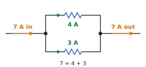
Charge is not created or stored at an ideal junction, so in steady operation the current flowing in equals the current flowing out. This is Kirchhoff's current law:
If 7 A arrives and two paths leave carrying 4 A and 3 A, the books balance. At the return junction the branch currents merge again, so the return wire carries the full 7 A back to the source.
Label currents before calculating
Before doing any arithmetic, mark the diagram. Write the supply voltage across each branch, give each branch current a name such as I1, I2 and I3, and mark the total I_T entering the first junction and leaving the last one.
This habit keeps you from mixing up which resistor goes with which current, and it shows at a glance which quantities you know and which you need. Many wrong answer choices come from pairing the right numbers with the wrong branches.
Source current using the equivalent resistor
One way to get the total current is to collapse the network first. Find the equivalent resistance, then divide the supply voltage by it.
For a 24 V source across 12 Ω and 12 Ω, the equivalent is 6 Ω, so the source supplies
This route is fastest when the branches are equal or when product-over-sum gives a clean value.
Branch currents provide an independent check
A second route to the total current is to find each branch current with Ohm's law and add them. In the 24 V example with two 12 Ω branches, each carries 2 A, and 2 A plus 2 A is 4 A.
When both routes agree, you can trust the answer. If they disagree, one of the steps contains an error, often a forgotten reciprocal.
Power in each parallel resistor
Power is the rate at which a resistor turns electrical energy into heat, measured in watts. Because the voltage is known in parallel, the most convenient form is
You may also use
with the branch current. At 10 V, a 5 Ω branch dissipates
while a 20 Ω branch dissipates only 5 W. In parallel, the smaller resistor runs hotter.
Total power equals the sum of branch powers
Energy is conserved, so the power the source delivers equals the total of all the branch powers:
With the 10 V example from the previous section, 20 W plus 5 W is 25 W. The total current is 2 A plus 0.5 A, or 2.5 A, and
which matches. Both routes must give the same total.
A parallel open branch
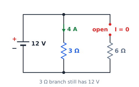
An open is a break in a path, such as a burned-out filament or a loose wire, so no current can flow through it. In the figure, the 6 Ω branch has been disconnected from a 12 V source, while the 3 Ω branch remains connected.
The 3 Ω branch still has the full 12 V across it, so it still carries
The only change is that the source no longer supplies the 2 A the 6 Ω branch used to draw. This is why one dead bulb in a parallel string leaves the others lit.
A short circuit across the rails
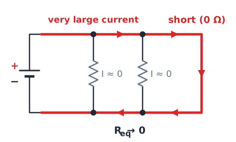
A short circuit is a path with essentially zero resistance. If a wire connects the two supply rails directly, it is in parallel with every other branch, and the equivalent resistance becomes zero.
In the ideal model, a fixed voltage across zero resistance would require unlimited current, which signals that the model has broken down. In reality the battery's internal resistance, wire resistance, a fuse or a breaker limits the current, but it can still be very large, hot and dangerous. The resistors get almost no current because the short takes it.
A wire bypasses one resistor
Placing a wire directly across a component forces the voltage between its two ends to zero, so that component stops carrying current. Its effect depends on where it sits.
In a series chain, shorting one resistor removes it, and the remaining resistors share the full supply. In a simple parallel group, though, every resistor spans the same two rails, so a wire across any one of them is a wire across all of them, and across the source. That is a full short of the supply, not a mild change.
What a switch controls
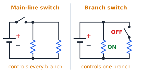
A switch is a deliberate open or closed point. A closed switch acts like a plain wire; an open switch acts like a break.
Where you place it decides what it controls. A switch in the main line before the first junction turns every branch on or off together. A switch inside one branch controls only that branch, while the others keep their voltage and current. This is why a room can have one light switch per fixture on a common circuit.
Why parallel loads are common
Household outlets and lights are wired in parallel for two main reasons. First, every device receives the same rated voltage, about 120 V in a U.S. home, no matter how many others are plugged in.
Second, each device works independently. Turning off a lamp or unplugging a toaster does not interrupt the refrigerator. The trade-off is that each added load increases the total current in the shared wiring, which is why circuits are protected by breakers.
The ideal fixed-voltage assumption
Most textbook and test problems assume an ideal source, meaning its terminal voltage stays the same no matter how much current is drawn. Under that assumption, adding or removing a branch never changes the voltage on the other branches.
Real sources have some internal resistance. When a heavy load is added, the terminal voltage sags a little, so the other branches see slightly less voltage. You may notice lights dim briefly when a large motor starts. Unless a question mentions internal resistance, use the ideal model.
Current capacity and safe operation
Because branch currents add, the wire and the source near the supply carry the largest current in a parallel circuit. Plugging too many heaters into one circuit can push that total beyond what the wiring is rated to handle.
Fuses and circuit breakers are placed in series with the supply line so they can open the whole circuit when the total current gets too high, preventing overheated conductors.
An ammeter belongs in series with the measured path
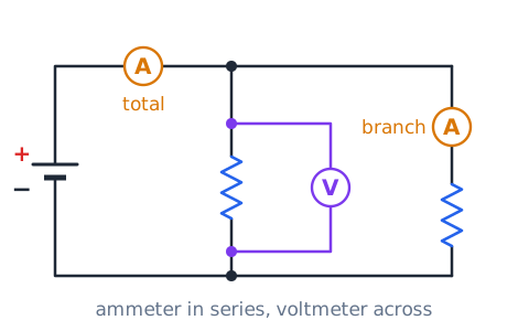
An ammeter measures the current flowing through it, so the circuit must be opened and the meter inserted in the path, making the current pass through the meter. To measure one branch, break that branch and insert the meter there; to measure the total, insert it in the main supply line.
An ideal ammeter has nearly zero resistance. Connecting it directly across a voltage source or across a branch is effectively a short, which can blow the meter's fuse or damage the meter.
A voltmeter spans two points
A voltmeter measures the potential difference between the two points its leads touch, so it is placed across a component, in parallel with it. The circuit does not need to be broken.
An ideal voltmeter has very high resistance, so it draws almost no current and does not disturb the circuit. In a parallel network, placing the leads across any one branch reads the same value as placing them across the source.
Ohmmeter measurements use an unpowered circuit
An ohmmeter works by sending its own small test current through the part and measuring the result. If the circuit is powered, outside current spoils the reading and can damage the meter, so always turn off and disconnect the power first.
Also remember that other parallel branches give the test current extra paths. To read a single resistor's true value, disconnect at least one of its ends from the circuit.
Equivalent resistance is not always a whole number
Clean answers are common on tests, but the formula does not promise them. For example, 4 Ω in parallel with 6 Ω gives a product of 24 and a sum of 10, so the result is 2.4 Ω.
A decimal or fraction is fine as long as it is smaller than the smallest branch. If answer choices include a fraction like 12/5 Ω, that is the same value written another way.
Three-branch reciprocal arithmetic
With three branches, convert each reciprocal to a common denominator. For 4 Ω, 6 Ω and 12 Ω, the common denominator is 12:
So
Using the least common multiple of the resistances keeps the numbers small and avoids decimal rounding.
Adding a resistor below the smallest value
Suppose a network already contains 10 Ω and 15 Ω in parallel, giving 6 Ω. If you add a 2 Ω branch, it carries the largest current of all, and the new equivalent falls below 2 Ω.
In general, the equivalent is always smaller than the smallest branch, so a newly added small resistor pulls the total down sharply. A newly added very large resistor barely changes it. Either way, adding a positive resistor in parallel can only lower the total.
Removing a branch and the direction of change
Removing a branch, or letting it open, does the reverse of adding one. With fewer paths for current, the equivalent resistance rises and, for a fixed source, the total current falls.
The current lost is exactly the current that branch was carrying. If a 120 V circuit feeds a 10 A heater and a 1 A lamp and the heater is unplugged, the total drops from 11 A to 1 A, while the lamp keeps its 1 A.
Distinguish resistor fault types
An open fault means a path has infinite resistance: its current drops to zero, the total current falls, and the equivalent resistance rises. The other branches are unaffected under an ideal source.
A short fault means a path has zero resistance: in a simple parallel group it shorts the whole group and the source. A drifted or wrong-value resistor is the mildest case. If its resistance rises, its current falls; if its resistance drops, its current and heat rise. Name the fault before predicting its effects.
Comparison with series circuits
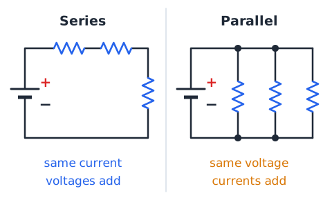
In series, one path carries the same current through every part, the voltages add up to the source voltage, and the total resistance is the sum, so it is larger than any single part. One open stops everything.
In parallel, every branch has the same voltage, the currents add up to the source current, and the total resistance is smaller than any single branch. One open stops only its own branch. Keep this table in your head; many test choices simply swap the two sets of rules.
Series–parallel combinations must be reduced in stages
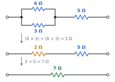
Many circuits mix the two connections. Reduce them step by step. First combine any group whose members truly share two nodes, then treat that result as one resistor and combine it in series with whatever follows.
For example, 6 Ω parallel with 3 Ω is 2 Ω, and that block in series with 5 Ω gives
Then use
for the source current and work back outward to find individual voltages and currents.
Shared node voltage in a mixed circuit
In a mixed circuit, a parallel group no longer receives the full supply voltage, because a series resistor ahead of it uses some voltage first.
The group's members still share one voltage with each other, though. Find that common value as the source voltage minus the series drop, or as the total current times the group's equivalent resistance. Then use it for each branch inside the group.
The order of circuit reduction matters
Combine from the inside out, starting with the parts farthest from the source. Only merge two resistors in parallel if both of their ends meet at the same two nodes, and only merge two in series if nothing else branches off between them.
A common mistake is to add a series resistor to just one member of a parallel group before combining the group. That changes the circuit into something different. Redraw the circuit after each step so every new equivalent resistor appears clearly in its proper place.
Using source current to find an unknown resistor
Sometimes you know the source voltage, the total current and all but one branch. Find each known branch current with Ohm's law, subtract them from the total to get the unknown branch current, and then divide the voltage by that current.
This uses Kirchhoff's current law first and Ohm's law second. It avoids any reciprocal arithmetic.
Reverse calculations with equivalent resistance
You can also work backward from the equivalent resistance. If the network must equal 4 Ω and one branch is 12 Ω, then the missing branch satisfies 1/4 minus 1/12 equals 1/R.
That is 3/12 minus 1/12, or 2/12, so R is 6 Ω. Check it: 12 times 6 over 18 is 4 Ω.
Unit recognition: ampere, volt, ohm and watt
Know the four core units cold. Current is in amperes (A), voltage in volts (V), resistance in ohms (Ω) and power in watts (W). They connect through two equations:
So one volt equals one ampere times one ohm, and one watt equals one volt times one ampere. If a choice gives a current in ohms or a power in volts, eliminate it immediately.
Milliampere conversions
Small circuits often use milliamperes (mA) and kilohms (kΩ). One milliampere is one thousandth of an ampere, so 1 A equals 1,000 mA and 0.25 A equals 250 mA.
A handy fact is that volts divided by kilohms gives milliamperes directly. For example, 6 V across 2 kΩ gives 3 mA, with no need to convert to amperes first.
Power depends on the common parallel voltage
Because each parallel branch has the same voltage, its power depends only on its resistance:
So power is inversely proportional to resistance in parallel. At 120 V, a 12 Ω heating element dissipates
while a 240 Ω lamp uses only 60 W. If the supply voltage doubled, every branch's power would become four times larger, because voltage is squared.
A power check from total resistance
Total power can also be found from the equivalent resistance as the voltage squared divided by R_eq. For 10 V across 4 Ω and 4 Ω, the equivalent is 2 Ω, so total power is 100 divided by 2, or 50 W.
Each branch alone gives 100 divided by 4, or 25 W, and 25 plus 25 is 50 W, a match.
When resistance changes with temperature
Ideal resistors are assumed to have a constant value, but many real conductors change with temperature. A metal lamp filament, for example, has far higher resistance when glowing than when cold.
That means a bulb draws a brief surge of current at switch-on, then settles. Exam problems usually ignore this effect. If a question says "ideal" or gives fixed resistances, use those values exactly and do not try to correct them for heating.
Conventional current direction
Circuit diagrams use conventional current, which is drawn flowing out of the positive terminal, through the external circuit, and back into the negative terminal. In metal wires, the actual moving charges are electrons, which drift the opposite way.
For calculating currents, voltages, resistance and power, the choice of direction does not change any magnitudes. Just stay consistent: at each junction, count currents flowing in versus flowing out using the same convention throughout.
What happens to an intact branch under a fault
With an ideal source, an intact branch is protected from what happens elsewhere, as long as it still connects to the same two rails and the rails remain at the source voltage. If another branch opens, the intact branch keeps the same voltage, current and power.
The exception is a short across the rails. Then the rail voltage collapses toward zero in a real circuit, and the intact branches lose their current as well, while the source or protection device is stressed.
Care with ideal shorts and division by zero
If you try to use Ohm's law on an ideal short, you end up dividing a voltage by zero ohms, which has no finite answer. That is a sign that the ideal model is not describing what would really happen.
On a test, the correct answer to a direct short across a supply typically says the current becomes very large, limited only by real-world resistance, internal resistance or a fuse. Avoid choices claiming the resistors share extra voltage or that a finite exact current results.
Testing numerical answers for size
Use quick size checks to catch mistakes. The equivalent resistance must be lower than the smallest branch. The total current must be larger than the largest branch current. Each branch voltage must equal the supply voltage for a simple parallel group.
If you calculate 18 Ω for resistors of 6 Ω and 12 Ω in parallel, you added them as if they were in series. The real answer is 4 Ω, and only a value under 6 Ω could be right.
Fast no-calculator method for two equal branches
Two equal resistors in parallel always combine to half of one of them:
So 100 Ω with 100 Ω gives 50 Ω, and 470 Ω with 470 Ω gives 235 Ω. If the two are nearly equal, the answer is close to half of either one, which helps you eliminate choices. For 10 Ω and 11 Ω, expect a little more than 5 Ω; the exact value is
Use product-over-sum carefully
Product-over-sum works for exactly two resistors at a time. For three or more, you may apply it to two, then combine that result with the third, and so on, but you may not multiply all three values and divide by their sum.
Also watch the order of operations: divide the product by the full sum. For 3 Ω and 6 Ω, 18 divided by 9 is 2 Ω. Errors such as 18 over 3 plus 6 typed into a calculator without parentheses give a wrong answer.
Track the voltage across each stage
In a mixed circuit, write the voltage across every block as you go. Start with the source voltage, then subtract each series drop to find what is left for the next stage.
The voltages around any complete loop must add up to the source voltage. If a series resistor uses 4 V of a 10 V supply, the parallel group after it has 6 V across each of its branches, not 10 V. Writing these values on the diagram prevents using the full supply where it does not apply.
Do not confuse components with branches
A branch is a path, not a single part. One branch can hold several components in series, such as a resistor and a lamp, and they all carry the same branch current.
Counting resistors instead of paths leads to mistakes, such as dividing by the wrong number of equal branches. Before calculating, count how many separate paths run between the two nodes, then work out each path's total resistance.
Two resistors in one branch
When a branch contains two resistors in series, add them first to get the branch resistance, then treat that branch as one resistor in the parallel calculation.
The branch voltage equals the supply voltage, but it is split between the two resistors in proportion to their values. So each resistor in that branch sees only part of the supply.
Independent branches versus independent sources
Parallel branches are independent in the sense that each one draws its current according to its own resistance, without affecting the others, as long as the source voltage holds steady.
This differs from a circuit with more than one source. Two batteries connected together interact, and their currents can oppose or add. ASVAB parallel questions almost always use one source feeding several loads. Do not assume separate sources unless the diagram clearly shows them.
Topology before arithmetic
Topology means how parts are connected, regardless of how they are drawn. Before plugging in numbers, decide which parts are in series, which are in parallel, and which are neither.
Redraw a messy schematic with the source on the left, the top rail across the top and the bottom rail across the bottom. Hang each branch between the rails. A diagram drawn at angles or with crossing wires often turns out to be a simple parallel network once you trace each node.
Three-way consistency test
For a parallel network, three independent routes should give the same total power. First, from the equivalent resistance:
Second, from the total current:
Third, from adding each branch's .
Example: 6 V across 2 Ω and 3 Ω. The equivalent is 1.2 Ω, so
The total current is 3 A plus 2 A, or 5 A, so
The branches give 18 W plus 12 W, also 30 W. All three agree, so the work is sound.
Electricity safety and exam limits
This lesson uses low-voltage ideal models for learning. Real circuits, especially household wiring, can deliver currents that cause burns, fires and fatal shocks. Never test ideas from this lesson on live mains wiring or by shorting a battery.
Work on electrical equipment requires training, de-energizing the circuit, and following lockout procedures. On the test, answer based on the stated model; in real life, treat every circuit as live until a qualified person confirms otherwise.
Conceptual summary before practice
Before starting problems, restate the core rules. Parallel parts share the same two nodes, so they share one voltage. Each branch current is that voltage divided by the branch resistance. The branch currents add up to the source current.
The equivalent resistance is always smaller than the smallest branch, and adding a branch lowers it while removing one raises it. Branch powers add to the total. An open branch affects only itself; a short across the rails affects everything. Mixed circuits are reduced in stages.
Two branches at 12 V
Problem: a 12 V ideal source feeds a 3 Ω branch and a 4 Ω branch in parallel. Find each branch current, the total current and the equivalent resistance.
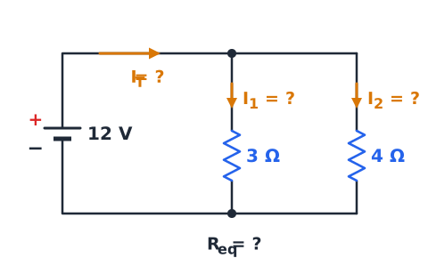
Each branch has 12 V. The 3 Ω branch carries
A and the 4 Ω branch carries
The total is 7 A. The equivalent is
Answer: 4 A, 3 A, 7 A total, and about 1.71 Ω.
Two-resistor shortcut
Problem: find the equivalent resistance of 10 Ω and 15 Ω in parallel.
Step 1: product,
Step 2: sum,
Step 3: divide:
Check: 6 Ω is below the smaller resistor, 10 Ω, as required. Answer: 6 Ω.
Three branches with clean reciprocals
Problem: find the equivalent of 10 Ω, 15 Ω and 30 Ω in parallel.
Use 30 as the common denominator:
Flip the result to get the answer:
which is less than 10 Ω.
Equal resistor shortcut
Problem: four 20 Ω resistors are connected in parallel across 10 V. Find the equivalent resistance and the total current.
Equal branches:
Total current:
Check: each branch carries
and four branches give
Answer: 5 Ω and 2 A.
Current conservation at a junction
Problem: 10 A enters a junction. Three branches leave it. Two of them carry 2.5 A and 4 A. Find the third.
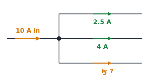
By Kirchhoff's current law, the outgoing currents must total 10 A:
Answer: 3.5 A. At the return junction, the three branch currents recombine into the same 10 A.
Branch resistance from known current
Problem: a parallel branch connected across a 9 V source carries 0.75 A. What is its resistance?
The branch has the full 9 V across it, so rearrange Ohm's law:
Check:
Answer: 12 Ω.
Adding a new branch
Problem: a 24 V source drives a single 12 Ω resistor. An 8 Ω resistor is then added in parallel. How do the total current and equivalent resistance change?
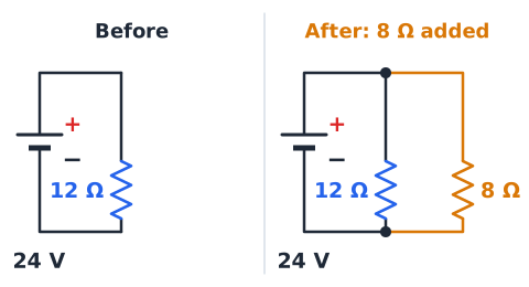
Before:
The new branch adds
while the 12 Ω branch still draws 2 A. New total: 5 A.
New equivalent:
which matches
Answer: current rises from 2 A to 5 A; resistance falls from 12 Ω to 4.8 Ω.
One branch opens
Problem: a 6 V source feeds 2 Ω and 3 Ω in parallel. The 3 Ω resistor burns open. Find the total current before and after.
Before:
A plus
a total of 5 A.
After: the open branch carries 0 A. The 2 Ω branch still has 6 V and still carries 3 A. Answer: the total current falls from 5 A to 3 A, and the intact branch is unchanged.
Power across unequal parallel resistors
Problem: a 9 V source feeds 3 Ω and 9 Ω in parallel. Find each power and the total.
Total: 36 W. Check: currents are 3 A and 1 A, so
The smaller resistor dissipates more power.
Series resistor before two branches
Problem: a 20 V source feeds a 4 Ω series resistor, followed by two 12 Ω resistors in parallel. Find the source current and each branch current.
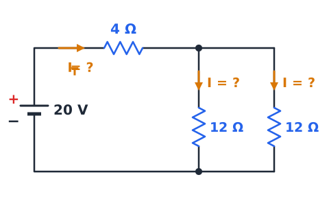
Parallel block:
Total:
The 4 Ω resistor drops
leaving 12 V across the parallel block. Each 12 Ω branch carries
Check: 1 A plus 1 A equals 2 A.
Two resistors in a single branch
Problem: a 12 V source feeds branch A, which holds 1 Ω and 5 Ω in series, and branch B, a single 4 Ω resistor.
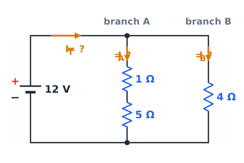
Branch A:
so it carries 2 A. Branch B carries
Total: 5 A, so
Inside branch A, the 5 Ω resistor drops
V and the 1 Ω drops 2 V, adding to 12 V.
Ratio without full calculation
Problem: 5 Ω and 20 Ω are in parallel and the source supplies 10 A total. Find each branch current without knowing the voltage.
The currents are in inverse ratio, 20 to 5, or 4 to 1. Split 10 A into 5 equal parts of 2 A: the 5 Ω branch gets 8 A and the 20 Ω branch gets 2 A.
Check the shared voltage:
V and
A milliamperes network
Problem: a 5 V source feeds 1 kΩ and 2.5 kΩ in parallel. Find the branch and total currents.
Volts over kilohms gives milliamperes:
mA and
mA. Total: 7 mA, or 0.007 A.
Check: the shortcut gives
Reverse unknown branch from source data
Problem: a 30 V source supplies 8 A to two parallel branches. One is 10 Ω. Find the other.
The known branch carries
so the unknown branch carries
Its resistance is
Check:
Guided drill: shared node test
Prompt: two resistors are drawn on opposite sides of a page, but each one's left end connects by bare wire to the battery's positive terminal and each right end to the negative terminal. Are they parallel? Answer: yes, they share both nodes.
Prompt: resistor A connects to resistor B, and nothing else meets at that point. Answer: they are in series, not parallel.
Prompt: two resistors have equal values. Does that make them parallel? Answer: no, equal value says nothing about connection.
Guided drill: current split
Prompt: an 8 V source drives 2 Ω and 8 Ω in parallel. What is the current in the 2 Ω branch? Answer: 4 A.
Prompt: what is the current in the 8 Ω branch? Answer: 1 A.
Prompt: what is the source current? Answer: 5 A.
Prompt: which branch carries more? Answer: the 2 Ω branch.
Guided drill: reciprocal arithmetic
Prompt: 6 Ω parallel with 3 Ω? Answer: 2 Ω.
Prompt: three 12 Ω resistors in parallel? Answer: 4 Ω.
Prompt: 8 Ω parallel with 24 Ω? Answer: 192 over 32, which is 6 Ω.
Prompt: is 9 Ω a possible result for 8 Ω and 24 Ω in parallel? Answer: no, it exceeds 8 Ω.
Guided drill: one open branch
Prompt: a 10 V source feeds 5 Ω and 10 Ω in parallel. What is the total current? Answer: 2 A plus 1 A, or 3 A.
Prompt: the 10 Ω branch opens. What is the new total? Answer: 2 A.
Prompt: what is the voltage across the 5 Ω resistor now? Answer: still 10 V.
Prompt: did the equivalent resistance rise or fall? Answer: it rose.
Guided drill: mixed network
Prompt: a 15 V source feeds 1 Ω in series with two 8 Ω resistors in parallel. What is the total resistance? Answer: 1 Ω plus 4 Ω, or 5 Ω.
Prompt: source current? Answer: 3 A.
Prompt: voltage across the parallel pair? Answer: 15 V minus 3 V, or 12 V.
Prompt: current in each 8 Ω branch? Answer: 1.5 A.
Guided drill: unit and power check
Prompt: a 12 V branch carries 250 mA. What is its power? Answer: 12 times 0.25, or 3 W.
Prompt: what is the current in a 2 kΩ branch at 10 V? Answer: 5 mA.
Prompt: its power? Answer: 10 V times 0.005 A, or 0.05 W.
Prompt: which unit fits power? Answer: watts.
Common wrong answers to eliminate
Adding parallel resistances as if they were in series gives a value bigger than any branch, which is impossible. Dividing the source voltage among the branches is a series idea; parallel branches each get the full voltage. Assuming equal currents in unequal branches ignores Ohm's law. Forgetting the final flip in the reciprocal rule leaves an answer in siemens.
Another trap is believing an open branch shuts off the whole circuit or raises the voltage on the others. With an ideal source, intact branches stay exactly as they were. Eliminate these choices first.
ASVAB exam method for parallel networks
Use a steady routine. First, trace the nodes and decide what is in parallel. Second, write the voltage on every branch; for a simple group it is the source voltage. Third, find branch currents with V divided by R. Fourth, add them for the total, or divide the voltage by the equivalent resistance.
Then sanity-check: the equivalent must be below the smallest branch, and the smallest resistor must carry the most current. For a conceptual question, picture removing or adding one path and ask what changes. Skip heavy math when ratios alone pick the answer.
Final recall checklist
Parallel parts connect across the same two nodes, and that is the only test that matters.
Voltage is the same on every branch:
Branch current is
Currents add:
For two resistors, use ; for n equal ones, use . The equivalent is always below the smallest branch. Adding a branch lowers it and raises total current; removing one does the opposite.
Power per branch is , so the smallest resistor dissipates the most, and branch powers add to . An open branch affects only itself under an ideal source; a short across the rails draws very large current until something limits it. Reduce mixed circuits from the inside out, track the voltage at each stage, and measure current in series, voltage across, and resistance with the power off.
 English ▾