 ASVAB Camp
Lesson goal and scope
This lesson applies magnetism to the three machines that move most electrical power: motors, generators, and transformers. You will learn to tell which device is which from a description, name their main parts, and explain the role of commutators, slip rings, back emf, and turns ratio.
You will also solve the short calculations that appear on Electronics Information: electrical and mechanical power, efficiency, average induced emf, generator frequency from poles and speed, ideal transformer voltage and current, motor current with back emf, and transmission line loss.
Energy conversion is the organizing idea
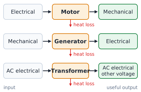
The fastest way to sort these machines is to ask what kind of energy goes in and what kind comes out. A motor takes in electrical energy and delivers mechanical energy, a turning shaft. A generator takes in mechanical energy and delivers electrical energy. A transformer takes in AC electrical energy and delivers AC electrical energy at a different voltage, with no moving parts.
None of them creates energy. Each passes most of its input to the output and loses the rest, mainly as heat. Keep this input-output picture in mind and nearly every identification question becomes simple.
Identify the motor in an everyday system
Look for the part that receives electric power and makes something move. In a ceiling fan, the motor spins the blades. In a cordless drill, the battery feeds a motor that turns the chuck. A washing machine motor turns the drum, a refrigerator motor drives the compressor, and an electric car's motor turns the wheels.
The clue is direction of flow: wire or battery in, motion out. A motor has a stationary part, the stator, and a rotating part, the rotor, which carries the shaft. If a description says electricity is used to turn, push, or pump, a motor is involved.
Identify the generator in an everyday system
A generator is found wherever motion is used to make electricity. A portable gasoline generator uses an engine to spin it. A wind turbine's blades turn one, and so do steam and water turbines at power plants. A car's alternator is a generator driven by the engine belt, and a hand-crank emergency radio contains a small one.
The clue is reversed from a motor: mechanical motion in, electrical output out. If a question names a turbine, crank, engine, or falling water as the source and a lamp or battery as the receiver, the device is a generator.
Motor and generator structures can resemble each other
Motors and generators use the same building blocks: coils of copper wire, magnets or electromagnets, a stator, a rotor, and bearings for the shaft. A small permanent-magnet DC motor and a small DC generator can look identical on a bench.
In fact, spin the shaft of such a motor by hand with a meter attached and it produces a voltage, acting as a generator. Electric and hybrid vehicles use this in regenerative braking, letting the drive motor act as a generator to recharge the battery. So identify the device by its job, not its appearance.
Magnetic force produces motor torque
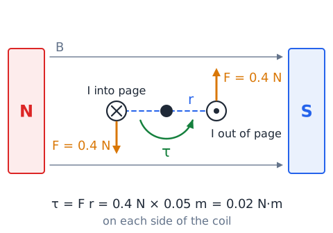
A motor turns because current-carrying wires in a magnetic field feel a force,
when the wire crosses the field. The two sides of a rotor coil carry current in opposite directions, so they are pushed in opposite directions, creating a twist about the shaft. That twist is torque:
where F is the force in newtons and r is the lever arm in meters, giving torque in newton-meters. Example: 0.4 N acting 0.05 m from the shaft gives 0.02 N·m on that side. More current, a stronger field, or more turns all give more torque.
Current direction and magnetic field direction
The direction a motor turns depends on two things: the direction of the current in the rotor and the direction of the magnetic field from the stator. Reverse either one and the force on each wire reverses, so the motor spins the other way. Reverse both and the rotation stays the same, because the two reversals cancel.
This is why swapping the two leads of a small permanent-magnet DC motor makes it run backward. It is also why a universal motor, which has an electromagnet field wired in series with the rotor, can run on AC: both directions flip together every half cycle.
What a commutator does in a brushed DC motor
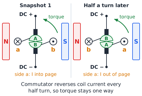
If a rotor coil fed with steady DC were simply connected to the supply, it would turn until its sides faced the poles and then rock back, because the forces would then push it backward. The commutator prevents this.
A commutator is a ring split into insulated segments mounted on the shaft. Carbon brushes press against it and feed it current. As the rotor turns, the brushes slide from one segment to the next, reversing the current in the coil every half turn at just the right moment. The torque therefore stays in one rotational direction, and the motor keeps spinning.
Brushless motors still require controlled switching
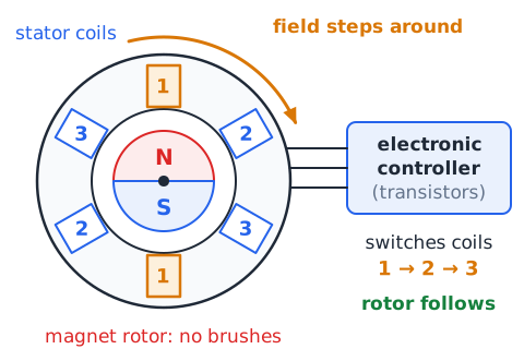
Brushes wear out, spark, and create electrical noise. A brushless DC motor removes them by putting the permanent magnets on the rotor and the coils on the stator. Since the coils no longer move, no sliding contact is needed.
The reversing job does not disappear, though. An electronic controller uses transistors to switch current between stator coils in sequence, guided by sensors or by measuring the coils' own voltages. This electronic commutation creates a field that steps around the stator and the magnet rotor follows. Computer fans, drones, and power tools commonly use this design.
DC motor versus AC motor
A DC motor runs from a steady supply such as a battery. Brushed versions use a commutator to reverse rotor current, and speed is easy to adjust by changing the applied voltage.
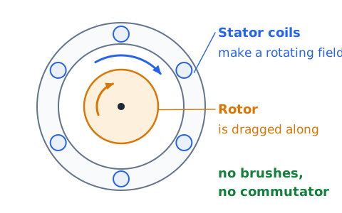
An AC motor runs from alternating current, which already reverses direction many times a second. In the common induction motor, the stator coils create a field that rotates around the machine, and that field induces currents in the rotor, which then gets dragged along. No brushes or commutator are needed, so induction motors are rugged and common in pumps, fans, and compressors. Their speed is tied to supply frequency.
Back emf is generated by a turning motor
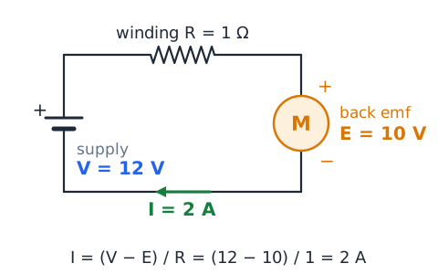
A spinning motor's rotor coils cut through the magnetic field, so the motor also acts as a generator. The voltage it produces, called back emf (E), opposes the supply voltage V. The current is set by what is left over across the winding resistance R:
Example: 12 V supply, 10 V back emf, 1 winding gives
Back emf grows with speed, so a motor draws less current once it is up to speed than when it is starting.
Stall current and heating
When a motor is first switched on, or when its shaft is jammed, it is not turning, so it produces no back emf. The only thing limiting current is the small winding resistance, so the current can be many times the normal running value. This is called stall current or locked-rotor current.
Because heating in the windings rises with the square of current, a stalled motor heats very quickly and can burn its insulation. That is why a jammed blender smells hot, why motor circuits use fuses or thermal overload protection, and why lights may dim briefly when a large motor starts.
Motor electrical input power
The electrical power a DC motor takes from its supply is
with V in volts, I in amperes, and P in watts. A motor running from 24 V and drawing 3 A takes
This is the input, not the useful output. Some of it becomes heat in the windings and some is lost to friction, so the shaft always delivers less than this amount. For AC motors the calculation also involves power factor, but EI-level questions usually give a simple DC case.
Motor mechanical output power
The useful output of a motor is mechanical power at its shaft:
where is torque in newton-meters and is angular speed in radians per second. The product is in watts. A shaft delivering 0.5 N·m at 100 rad/s gives 50 W. For linear motion the same idea appears as force times speed. Mechanical power can also be quoted in horsepower; one horsepower is about 746 W. Always convert to watts before comparing with electrical input.
Motor efficiency is an output-to-input ratio
Efficiency tells what fraction of the input becomes useful output:
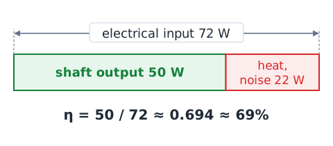
Both powers must be in the same unit. Using the previous figures, a motor taking 72 W and delivering 50 W has
about 69 percent. The other 22 W becomes heat and noise. Efficiency can never exceed 100 percent; an answer above that means the fraction was written upside down.
Faster motors are not automatically more powerful
Mechanical power depends on both torque and speed, not speed alone. A tiny hobby motor may spin at 15,000 rpm but deliver only a few watts because its torque is tiny. A large winch motor may turn slowly yet deliver kilowatts because its torque is huge.
Gearboxes show the trade-off clearly. A gear reduction lowers speed and raises torque by about the same factor, so power stays roughly the same, minus a little friction loss. When comparing motors, compare power in watts or horsepower, not just rpm.
Motors respond to mechanical load
A motor adjusts automatically to the work demanded of it. When a load is added, such as a drill bit biting into wood, the motor slows slightly. Lower speed means lower back emf, so more current flows, which produces more torque to meet the load. Remove the load and the motor speeds up, back emf rises, and current falls.
That is why an unloaded motor draws little current and a heavily loaded one draws much more. It also explains why overloading a motor is dangerous: the load drags it toward stall, current climbs, and the windings overheat.
Generators require an energy source
A generator does not create electrical energy; it converts mechanical energy that something else supplies. That source might be burning fuel in an engine, steam from a boiler, falling water in a dam, wind on turbine blades, or a person turning a crank.
If the source stops, the shaft slows and the output falls to zero. A generator with no load still needs a little input to overcome friction, and the more electrical power it delivers, the more mechanical power it needs. Claims of a generator that powers itself or runs forever contradict energy conservation.
How electromagnetic induction produces voltage
A generator works by electromagnetic induction. As its coil rotates in a magnetic field, the flux through the coil keeps changing, and a changing flux induces an emf. Faraday's law gives the average value:
N is the number of turns, the change in flux per turn in webers, and the time in seconds. More turns, a stronger field, a larger coil area, or faster rotation all increase the voltage. A steady flux, with no motion, induces nothing.
AC output of a simple rotating-loop generator
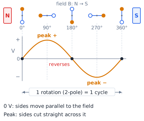
Picture a single loop spinning steadily between two magnet poles. During half of each turn, one side of the loop moves up through the field while the other moves down, producing voltage in one direction. During the next half turn the sides swap roles and the voltage reverses.
The result is alternating voltage that rises, falls, and reverses smoothly in a sine-wave shape. Voltage is greatest when the loop's sides cut straight across the field and zero at the instant they move parallel to it. One full rotation of a two-pole machine gives one complete cycle.
Slip rings versus a split-ring commutator
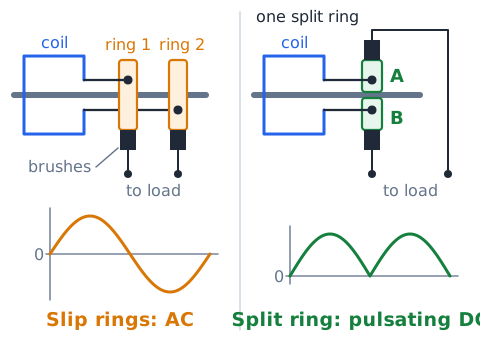
A rotating coil needs a sliding connection to the outside circuit, and the type of connection decides the output. Slip rings are two separate, continuous rings, each joined to one end of the coil. Brushes ride on them, and the external circuit sees exactly what the coil produces, which is alternating current. This is the arrangement in an AC generator, or alternator.
A split-ring commutator is one ring cut into segments. It reverses the coil connections every half turn, so the output always points the same way. That gives pulsating DC, not smooth DC. In a motor, the same commutator reverses current to keep torque steady.
DC output may need commutation or rectification
Every rotating coil naturally produces alternating voltage. There are two ways to get direct current from it. The older way is a mechanical commutator, which flips the connections each half turn. The modern way is to let the machine make AC and then pass it through a rectifier, a set of diodes that allow current in only one direction.
A car alternator is a good example: it generates three-phase AC, and a built-in diode rectifier converts it to DC for charging the battery. Note that a transformer cannot do this job, and an inverter does the opposite, turning DC into AC.
A generator can feel harder to turn under load
Spin a hand-crank generator with nothing connected and it turns easily. Connect a lamp and it suddenly becomes harder to crank. This is Lenz's law at work. Once current flows in the coil, the coil feels a magnetic force, and that force opposes the rotation that is producing it.
The extra effort is exactly how mechanical energy turns into electrical energy. More electrical load means more current, a stronger opposing force, and more work needed per turn. Power plants must therefore increase steam or water flow to their turbines when customer demand rises, or the generators slow down.
Frequency, poles, and generator speed
In a synchronous generator, output frequency depends on rotational speed and the number of magnetic poles:
where f is in hertz, p is the number of poles (always even), and n is the speed in revolutions per minute. The 120 converts minutes to seconds and pole pairs to poles. A six-pole machine at 1200 rpm gives
More poles let a slower machine make the same frequency, which suits slow water turbines.
Transformers change AC voltage levels
A transformer raises or lowers AC voltage. It has two coils wound on a shared iron core, with no wire connecting them. Alternating current in the first coil makes a constantly changing flux in the core, and that flux induces an AC voltage in the second coil.
Transformers are everywhere. Utility transformers on poles or pads reduce distribution voltage to the level used in homes. Small plug-in power supplies often contain a transformer to reduce wall voltage before converting it to DC. Power plants use large step-up transformers to raise voltage for long-distance transmission lines.
Primary and secondary mean input and output windings
The coil connected to the source is the primary winding. The coil connected to the load is the secondary winding. These names describe role, not size: the primary may have more or fewer turns than the secondary.
Do not mix these names up with motor terms. Rotor and stator belong to rotating machines. Anode and cathode belong to diodes and batteries. Emitter and collector belong to transistors. On a transformer, the input is the primary, the output is the secondary, and the voltage, current, and turn symbols carry subscripts p and s.
Turns ratio predicts ideal voltage ratio
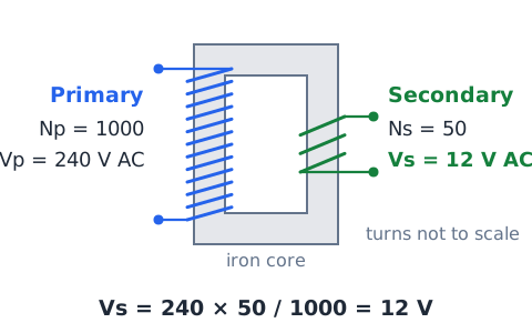
In an ideal transformer, the voltage per turn is the same on both windings, so voltage is proportional to turns:
Example: a 1000-turn primary on 240 V with a 50-turn secondary gives
To find needed turns, rearrange:
Always place secondary over primary on both sides, or both upside down, so the ratio stays consistent.
Step-up and step-down are voltage labels
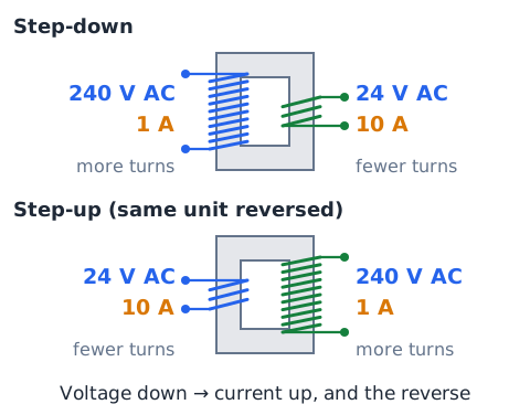
A step-up transformer has more turns on its secondary than on its primary, so its output voltage is higher than its input. A step-down transformer has fewer secondary turns, so its output voltage is lower.
The labels describe voltage only. Current moves the opposite way: a step-up transformer delivers less current than it draws, and a step-down transformer delivers more. Many transformers can also be connected in reverse, so one that steps 240 V down to 24 V will step 24 V up to 240 V if the windings are swapped. Ratings must still be respected.
Current ratio is inverse of the voltage ratio
For an ideal transformer, the current ratio is the inverse of the turns ratio:
If a transformer steps voltage down by a factor of 10, it steps current up by a factor of 10. Example: a 240 V to 24 V transformer delivering 10 A on its secondary draws only 1 A on its primary. Remember the shortcut: whichever side has the higher voltage has the lower current.
Ideal transformer power balance
An ideal transformer has no losses, so power in equals power out:
This one equation solves most current questions. Find the output power from the secondary values, then divide by the primary voltage to get primary current. Example: a secondary supplying 36 V at 2 A delivers 72 W; with a 120 V primary,
A transformer can trade voltage for current, but it cannot raise both at once.
A transformer is not a DC voltage divider
A transformer relies on changing flux. Connect its primary to steady DC and the flux becomes constant after the first instant, so the secondary produces no ongoing voltage. Worse, with no AC to limit it, the primary current is set only by the small wire resistance, so the winding can overheat quickly.
This sets it apart from a resistor voltage divider, which works on DC by dropping voltage across resistances. To change DC voltage, electronics use converter circuits that chop DC into pulses, pass them through a small transformer or inductor, and then rectify the result.
Magnetic cores and coupling
The core gives the flux an easy, closed path from one winding to the other. Iron and special steels have high permeability, so almost all the flux created by the primary also passes through the secondary. This close linkage is called tight coupling.
Cores are built from thin steel sheets, called laminations, insulated from each other to block eddy currents. Some small high-frequency transformers use ferrite, a ceramic magnetic material with very low eddy loss. Air-core coils couple weakly and are used mainly at radio frequencies.
Why high voltage helps with transmission
Power lines lose energy as heat in their resistance, and that loss depends on current squared:
For a fixed delivered power,
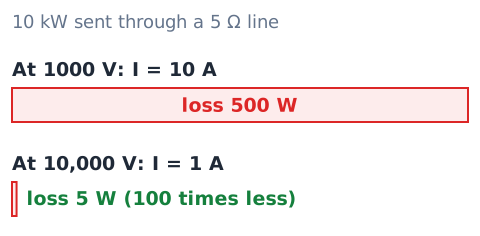
so higher voltage means lower current. Sending 10 kW at 1000 V takes 10 A; through 5 of line that wastes 500 W. At 10,000 V the current is 1 A and the loss is only 5 W. Raising voltage tenfold cuts loss a hundredfold, and doubling it cuts loss to one quarter. Transformers make this practical: they step voltage up at the power plant and back down near customers, which is the main reason grids use AC.
Transformer losses and efficiency
Real transformers lose some energy. Copper loss is heating in the windings. Core loss comes from eddy currents and hysteresis in the iron. A little flux also leaks without linking both coils. Efficiency is
A unit taking 500 W and delivering 470 W is 94 percent efficient; the 30 W difference becomes heat. Large power transformers often exceed 98 percent, among the most efficient machines built.
Electrical isolation is not guaranteed by every device
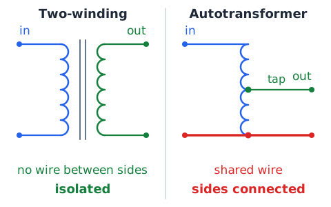
A conventional two-winding transformer has no direct wire connection between its primary and secondary, so it provides galvanic isolation: the output is not tied to the input circuit. Isolation transformers are used for this purpose in test benches and medical equipment.
Not every transformer-like device isolates. An autotransformer uses a single tapped winding shared by input and output, so the two sides are electrically connected. Some power supplies have no transformer at all. Even an isolated secondary can be hazardous at high voltage, so never assume a circuit is safe to touch.
A transformer can be rated in VA
Transformer nameplates usually give a rating in volt-amperes (VA) or kilovolt-amperes (kVA) rather than watts. The value is the rated voltage times the rated current, called apparent power. A secondary rated 24 V at 3 A is a 72 VA transformer.
The reason is that heating in the windings depends on current, and core loss depends on voltage, regardless of what kind of load is connected. Some loads, such as motors, draw current that does not all turn into real power. In the simple resistive problems used here, VA and watts are numerically equal.
Transformers do not change frequency
The secondary voltage is induced by the core flux, and that flux rises and falls at exactly the rate set by the primary current. So the secondary alternates at the same frequency as the primary. A 60 Hz input gives a 60 Hz output, whether the transformer steps voltage up or down.
Answer choices that claim a transformer doubles the frequency, turns AC into DC, or produces 0 Hz output are wrong. Changing frequency requires other equipment, such as an electronic frequency converter or a motor-generator set. Turning AC into DC requires a rectifier.
Motor and generator names are not interchangeable with adapters
Everyday language blurs names that a test keeps separate. A plug-in "power adapter" or charger is usually a transformer or switching power supply plus a rectifier; it produces DC from wall AC but has no rotating parts, so it is neither a motor nor a generator. An inverter turns DC into AC electronically, also without rotation.
A generator always involves mechanical input turning a shaft. A motor always produces mechanical output. Before answering, ask whether anything spins as part of the energy conversion. If nothing does, the device is not a motor or a generator.
Compare AC generator with transformer
Both devices rely on induction, and both produce AC output, but they differ in where the changing flux comes from. In an AC generator, mechanical rotation moves a coil and field relative to each other, so the input is mechanical energy. Its frequency depends on speed and pole count.
In a transformer, nothing moves. The changing flux comes from AC already present in the primary, so the input is electrical energy. Its output frequency equals the input frequency, and its job is only to change voltage and current levels. A transformer cannot start from mechanical motion or from DC.
Compare DC motor with DC generator
A brushed DC motor and a brushed DC generator have the same parts: field magnets, a rotor with coils, a commutator, and brushes. The difference is the direction of energy flow. In a motor, current from the supply produces force and rotation, and the commutator keeps torque in one direction.
In a generator, an outside source turns the rotor, induction makes voltage in the coils, and the commutator flips connections so the output stays in one polarity. Every running motor also generates back emf, and every loaded generator feels an opposing force. The machine is identified by its intended job.
Rotational speed conversion for mechanical power
Motor speed is usually given in rpm, but
needs radians per second. One revolution is radians and one minute is 60 seconds, so
Example: 600 rpm gives
rad/s. With 3 N·m of torque, power is about 188 W. Skipping this conversion is one of the most common calculation errors.
Frequency and rotation are linked but distinct
Generator frequency and shaft speed are related but are not the same number. A two-pole machine produces one electrical cycle per revolution, so 3600 rpm, or 60 revolutions per second, gives 60 Hz. A four-pole machine produces two cycles per revolution, so it needs only 1800 rpm for 60 Hz.
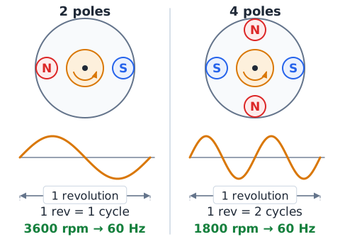
With poles fixed, frequency is directly proportional to speed. Increasing speed by 20 percent raises frequency by 20 percent. Hertz measures cycles per second; rpm measures turns per minute. Never give an rpm value as the answer to a frequency question.
Back emf versus externally supplied voltage
Keep three voltages separate in a running DC motor: the supply voltage V from outside, the back emf E produced by the rotor's own motion, and the drop across winding resistance, which is . They balance as
Example: a 36 V supply with 1.5 winding drawing 4 A has
Back emf is always less than the supply when the motor is driving a load; it is a result of rotation, not a second battery.
Separate watts from watt-hours
A watt measures power, the rate of energy flow at a given moment. A watt-hour measures energy, the total amount delivered over time. Multiply power by time in hours to get watt-hours.
Energy equals power times time. A 100 W motor running for 2 hours uses 200 Wh. A 500 W generator running for 30 minutes supplies 250 Wh. Utilities bill in kilowatt-hours, where 1 kWh equals 1000 Wh. A rating in watts tells how hard a device works; watt-hours tell how much it did in total.
Units for efficiency and turns ratio
Efficiency and turns ratio are both ratios of like quantities, so their units cancel. Efficiency is watts divided by watts, written as a decimal such as 0.85 or as a percentage such as 85 percent. Turns ratio is turns divided by turns, written as a pair like 10:1 or as a single number.
When writing a turns ratio, say which side is first. A 2000-turn primary with a 200-turn secondary is 10:1 primary to secondary, or 1:10 secondary to primary. Many test errors come from reading the ratio in the wrong order.
Do not confuse torque with electrical current
Torque is a mechanical twisting effect measured in newton-meters (or pound-feet). Current is a flow of charge measured in amperes. In a DC motor they are closely linked, because the torque comes from forces on current-carrying wires, and more current gives more torque.
But they are not the same quantity, and their units cannot be swapped. A question asking for torque needs an answer in N·m; a question asking for current needs amperes. Power ties them together through different routes:
electrically and
mechanically.
Induced voltage can exist without load current
A generator spinning with its output terminals open still produces a voltage. A meter across the terminals reads it, but no current flows because the circuit is incomplete. The same is true of a transformer secondary with nothing connected.
Current appears only when a load completes the circuit. At that point the output voltage usually sags a little because of winding resistance, and the generator becomes harder to turn. So induced emf depends on changing flux, while load current depends on whether a path exists. Do not assume zero current means zero voltage.
What happens when generator speed increases
Turn a generator faster and the flux through its coils changes more quickly. By Faraday's law, a faster rate of change means a larger induced emf, so output voltage rises roughly in proportion to speed if the field strength stays the same.
For an AC generator, frequency also rises in proportion to speed. That is why power plants hold their generators at a fixed speed to keep grid frequency steady, and why a portable generator's engine runs at a governed speed. Bicycle dynamo lights glow brighter as you pedal faster for the same reason.
What makes a transformer ratio calculation fair
The simple ratio formulas assume an ideal transformer: no winding resistance, no core loss, and all flux shared by both coils. They also assume AC input, since DC produces no steady output. Under these assumptions voltage scales with turns, current scales inversely, and power in equals power out.
If a question gives an efficiency, it is no longer ideal: compute output power, then divide by efficiency to find input power. Always check the input is AC, the turns are matched to the right side, and the answer keeps power out no larger than power in.
Electrical and mechanical safety boundaries
Motors, generators, and transformers combine electrical and mechanical hazards. Rotating shafts, belts, and fan blades can catch clothing or fingers. Motors can restart suddenly. Capacitors in motor and power supply circuits can hold a charge after power is removed. Transformer secondaries and generator outputs can be at dangerous voltages.
Portable generators also create carbon monoxide, a deadly gas, and must never run indoors or in garages. Never connect a portable generator directly to household wiring without an approved transfer switch. Real work on these machines requires lockout procedures and trained people.
Common three-device comparison
Motor: electrical energy in, mechanical energy out; works by magnetic force on current; parts include stator, rotor, and in brushed DC types a commutator; key numbers are torque, speed, and efficiency.
Generator: mechanical energy in, electrical energy out; works by induction from motion; uses slip rings for AC or a commutator for DC; frequency depends on speed and poles.
Transformer: AC electrical energy in, AC electrical energy out at a different voltage; works by induction from changing primary current; no moving parts; frequency unchanged; voltage follows turns, current follows the inverse.
Efficiency problems: write the correct fraction
Efficiency is always useful output divided by total input. For a motor, output is mechanical and input is electrical. For a generator, output is electrical and input is mechanical. For a transformer, both are electrical, but output is the secondary.
Before dividing, label each number as input or output. Convert both to watts. The smaller number goes on top. If your result is above 100 percent, you flipped the fraction. To find a missing input, divide output by efficiency as a decimal; to find output, multiply input by efficiency.
What the ASVAB tests at this level
Expect identification questions: which device is described, what the rotating part is called, what a commutator or rectifier does, and what the two transformer coils are called. Expect concept checks: transformers need AC, do not change frequency, and trade voltage for current.
Calculations are short, usually one or two steps with friendly numbers. Typical items ask for input power from volts and amps, efficiency, mechanical power from torque and speed, transformer output voltage or current, generator frequency, motor current with back emf, and line loss from .
Synthesis: power flows through real systems
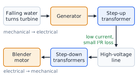
Follow energy from a dam to a kitchen. Falling water turns a turbine that drives a generator, which converts mechanical energy to electrical energy at a frequency set by speed and poles. A step-up transformer raises the voltage so that line current and loss are small. Near the city, step-down transformers lower the voltage in stages for safe use in homes.
In the kitchen, a blender motor turns that electricity back into motion. At each step a few percent is lost as heat, so overall efficiency is the product of the separate efficiencies.
Worked example 01 — identify the motor
Problem: A garage door opener plugs into a wall outlet. When the button is pressed, a chain drive lifts the door. A small transformer inside supplies low voltage to the control board. Which component is the motor?
Step 1: Look for electrical energy in and motion out.
Step 2: The transformer only changes voltage for the controls; nothing moves.
Step 3: The part that receives power and turns the chain sprocket converts electrical energy to mechanical energy.
Answer: the unit that drives the chain is the motor.
Worked example 02 — identify the generator
Problem: On a farm, a small water wheel in a stream turns a shaft connected to a machine that charges a battery bank. Which device is the generator?
Step 1: Find mechanical energy in. The water wheel supplies rotating shaft power.
Step 2: Find electrical energy out. The machine on the shaft charges batteries.
Answer: the machine driven by the water wheel is the generator.
Worked example 03 — motor input power
Problem: A conveyor motor operates from 36 V DC and draws 2.5 A. What is its electrical input power?
Step 1: Use
Answer: 90 W. This is the input; shaft output will be less because the windings warm up and the bearings add friction.
Worked example 04 — motor efficiency
Problem: The conveyor motor above takes 90 W and delivers 72 W of mechanical power. Find its efficiency.
Step 1:
Answer: 80 percent. The remaining
W is lost as heat and friction, never as useful work.
Worked example 05 — rotational mechanical power
Problem: A pump shaft delivers 4 N·m at 1200 rpm. Find the mechanical power.
Step 1:
rad/s.
Step 2:
Answer: about 503 W, roughly two-thirds of a horsepower. Using 1200 directly instead of rad/s would be badly wrong.
Worked example 06 — generator efficiency
Problem: A diesel engine delivers 2.0 kW of shaft power to a generator, which supplies 1.7 kW of electrical power. Find the generator's efficiency.
Step 1: Input is mechanical, 2.0 kW; output is electrical, 1.7 kW.
Answer: 85 percent.
Worked example 07 — average induced emf
Problem: A 40-turn generator coil's flux changes by 0.015 Wb per turn in 0.06 s. Find the average emf.
Step 1:
Wb/s.
Answer:
Halving the time to 0.03 s would double it to 20 V.
Worked example 08 — frequency from pole count
Problem: A slow hydroelectric generator has 8 poles and turns at 900 rpm. What frequency does it produce?
Step 1:
Answer: 60 Hz, the same as a two-pole machine at 3600 rpm.
Worked example 09 — step-down transformer
Problem: A control transformer has 2000 primary turns and 250 secondary turns. The primary is on 480 V AC. Find the secondary voltage.
Answer: 60 V AC, a step-down by a factor of 8.
Worked example 10 — step-up transformer
Problem: A transformer has 100 primary turns and 500 secondary turns, with 120 V AC on the primary. Find the output voltage.
Answer: 600 V AC, a step-up by a factor of 5.
Worked example 11 — ideal transformer current
Problem: An ideal transformer steps 240 V down to 24 V. Its secondary supplies 10 A to a heater. Find the primary current.
Step 1: Output power is
Step 2: Ideal means input power is also 240 W.
Answer: 1 A. Voltage fell by 10, so current rose by 10.
Worked example 12 — transformer efficiency
Problem: A transformer draws 400 W from its supply and delivers 380 W to its load. Find the efficiency and the loss.
Answer: 95 percent, with
W lost as heat in the windings and core.
Worked example 13 — back emf and motor current
Problem: A DC motor on a 48 V supply has 0.8 winding resistance. At full speed its back emf is 44 V. Find the running current and the current at stall.
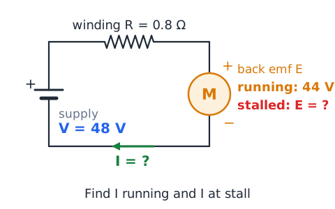
Step 1: Running:
Step 2: Stall: back emf is zero, so
Answer: 5 A running, 60 A stalled, twelve times larger.
Worked example 14 — transmission line loss
Problem: A line of 2 total resistance must deliver 20 kW. Compare loss at 2000 V and at 20,000 V.
Step 1: At 2000 V,
loss is
Step 2: At 20,000 V,
loss is
Answer: ten times the voltage gives one hundredth the loss.
Guided drill 1 — classify six machines
Name each as motor, generator, or transformer.
An electric toothbrush driving its bristles? Motor.
A wind turbine feeding the grid? Generator.
A pole-mounted unit reducing line voltage for homes? Transformer.
A car alternator? Generator, with a built-in rectifier.
A hybrid car's drive unit during regenerative braking? Acting as a generator.
A doorbell unit that drops 120 V AC to 16 V AC? Transformer.
Guided drill 2 — motor power and efficiency
A motor runs on 12 V and draws 5 A.
Input power?
It delivers 48 W of shaft power. Efficiency?
or 80 percent.
Power lost as heat and friction? 12 W.
Energy used in 2 hours?
Wh.
If a jam stops the shaft, what happens to current and output? Current rises sharply because back emf vanishes, and useful output drops to zero.
Guided drill 3 — generator induction reasoning
Predict the effect on induced emf.
The coil turns twice as fast? The emf doubles, because flux changes twice as quickly.
The coil has three times as many turns? The emf triples.
The rotor stops but the magnets stay in place? The emf drops to zero; no flux change.
The output terminals are left open? Voltage still appears, but no current flows.
A heavier load is connected? The shaft becomes harder to turn.
Guided drill 4 — a turns-ratio ladder
A 600-turn primary is on 120 V AC. Find each secondary voltage.
300 turns? 60 V.
150 turns? 30 V.
60 turns? 12 V.
1200 turns? 240 V.
Which of these are step-up? Only the 1200-turn secondary.
If the 60-turn secondary supplies 5 A, what is the ideal primary current? Output is
Guided drill 5 — spot the invalid DC claim
Decide whether each claim is valid.
A transformer on a 12 V car battery will give steady 120 V DC. Invalid; a transformer needs changing flux, so steady DC gives no ongoing output.
A rectifier can turn alternator AC into DC. Valid.
An inverter turns DC into AC. Valid.
A transformer changes 60 Hz to 120 Hz when it doubles voltage. Invalid; frequency is unchanged.
A commutator on a DC generator gives one-direction output. Valid.
Guided drill 6 — three-part power system
A small system has a generator at 90 percent efficiency, a transformer at 98 percent, and a motor at 85 percent.
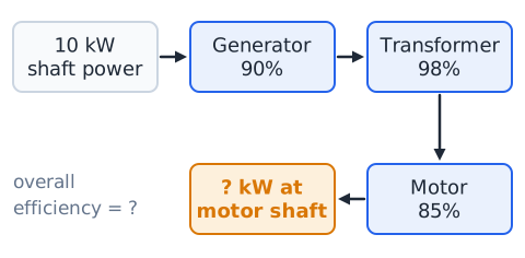
Which device converts mechanical to electrical? The generator.
Which converts electrical to mechanical? The motor.
Which has no moving parts? The transformer.
Overall efficiency? Multiply:
or about 75 percent.
If 10 kW of shaft power enters the generator, roughly how much reaches the motor shaft? About 7.5 kW.
Exam strategy — map device roles before computing
Before any calculation, sketch a quick energy map: what goes in, which device acts, and what comes out. Label each number as input or output, and as mechanical or electrical. This one habit prevents the most common errors, such as dividing efficiency upside down or using secondary values in the primary slot.
Then pick the single relation that fits:
Estimate first: a step-down transformer must give lower voltage and higher current. Eliminate any choice that breaks that logic.
Common mistakes — a practical checklist
Mistake: calling a transformer a generator. Fix: a generator needs mechanical input; a transformer has no moving parts.
Mistake: putting a transformer on DC. Fix: transformers need AC.
Mistake: saying a transformer changes frequency. Fix: output frequency equals input.
Mistake: raising both voltage and current. Fix: power in at least equals power out, so one goes down.
Mistake: efficiency above 100 percent. Fix: output goes on top.
Mistake: using rpm in
Fix: convert to rad/s.
Mistake: ignoring back emf. Fix: running current is ; stall current is .
Mistake: mixing watts and watt-hours. Fix: energy equals power times time.
Final recall — the ten facts to keep
A motor turns electrical energy into mechanical energy; a generator does the reverse; a transformer changes AC voltage without moving parts.
A brushed DC motor's commutator reverses coil current every half turn to keep torque in one direction; slip rings give AC from a generator.
Back emf grows with speed and limits running current; stall current is supply voltage over winding resistance.
Efficiency is output over input, always below 100 percent.
Mechanical power is torque times angular speed in rad/s.
Generator frequency is .
Transformer voltage follows turns; current follows the inverse; ideal power in equals power out.
Transformers need AC and keep frequency unchanged.
Raising transmission voltage lowers current, and loss falls with the square.
Watts measure power; watt-hours measure energy.
 English ▾