 ASVAB Camp
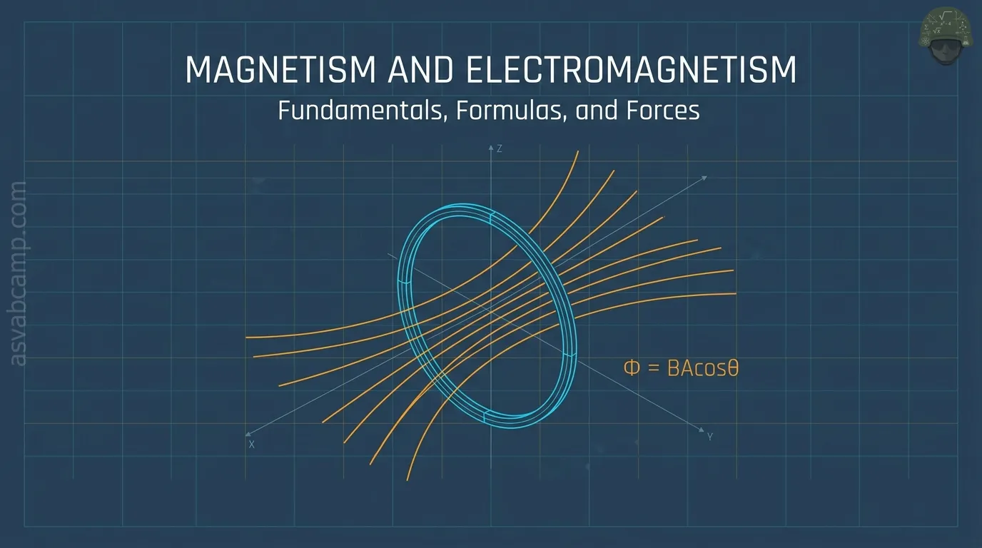
Lesson goal and scope
This lesson builds the magnetism background that Electronics Information questions assume. By the end you should be able to predict whether two poles push or pull, find the direction of the field around a current using your right hand, explain how coils and iron cores make controllable magnets, and describe how a changing magnetic flux creates a voltage.
You will also practice the short calculations that appear at this level: force on a wire, magnetic flux, induced voltage from Faraday's law, energy stored in an inductor, and the RL time constant.
Magnetism as an electrical topic
Magnetism shows up on an electronics test because electricity and magnetism are two sides of one interaction. Every moving charge produces a magnetic field, so any wire carrying current is surrounded by one. Going the other way, a magnetic field that changes near a conductor pushes charges along and creates a voltage.
Many everyday parts depend on this link. A doorbell chime uses a coil to pull an iron plunger. A speaker uses a coil and magnet to move a cone. A transformer, a motor, and a generator all exist only because current makes fields and changing fields make voltage. Learning the basic rules here makes those devices easy to understand later.
The north and south pole model
Every magnet has two regions where its effect is strongest, called poles. The end that turns toward Earth's geographic north when the magnet can swing freely is labeled the north-seeking or north (N) pole; the other end is the south (S) pole.
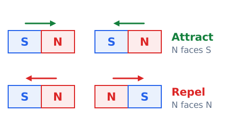
The rule for interaction is short: like poles repel and unlike poles attract. Two N ends pushed together resist, and so do two S ends, while an N end and an S end snap toward each other. The push or pull gets weaker quickly as the magnets are moved apart.
Cutting a magnet does not isolate one pole
A common trick question asks what happens if you saw a bar magnet in half to separate its north end from its south end. The answer is that you get two smaller magnets, each with its own N and S pole. Cut those again and the same thing happens.
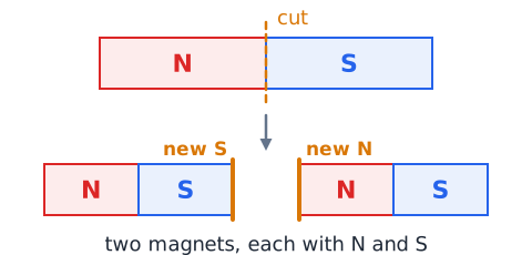
The reason is that a magnet's field comes from countless tiny magnetic regions lined up inside the material, and each region already has both poles. No matter where you cut, the pieces still contain aligned regions. In ordinary physics no one has found an isolated single pole, so any choice describing a "lone north pole" is wrong.
Magnetic field as a vector quantity
A magnetic field is described at every point by a size and a direction, which makes it a vector. Its strength, called magnetic flux density, has the symbol B and the SI unit tesla (T). One tesla is large; a refrigerator magnet near its surface is a few thousandths of a tesla, and Earth's field is only tens of microtesla.
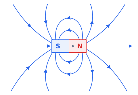
The direction of B at a point is defined as the way the north end of a small compass needle would point if placed there. Outside a bar magnet, that direction runs away from the N pole and around toward the S pole.
Read field lines carefully
Field lines are a drawing tool, not physical strings. Three rules let you read any field diagram. First, the arrow on a line shows the direction a compass north end would point at that spot. Second, where lines crowd close together the field is stronger, and where they spread apart it is weaker. Third, field lines never cross, because a point cannot have two field directions at once.
Outside a magnet the lines leave the N pole and enter the S pole; inside the magnet they continue from S back to N, so each line forms a closed loop.
Compass behavior and Earth field
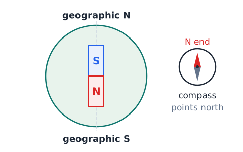
A compass needle is simply a small, lightweight magnet free to rotate. It lines up with whatever magnetic field is strongest at its location, so it shows the local field direction rather than temperature, voltage, or anything else.
Away from other magnets, the needle follows Earth's field, which is why it points roughly north. Because the needle's north end is attracted there, the magnetic pole near Earth's geographic north actually behaves like a magnetic south pole. Bring a current-carrying wire or a steel tool close and the compass will swing toward that nearer, stronger field instead.
Magnetic versus electrically charged
Do not confuse magnetic poles with electric charges. A positive or negative charge is a surplus or shortage of electrons, and it attracts or repels other charges even when everything is at rest. A magnetic pole is not a charge, and a magnet is normally electrically neutral.
A practical test: a rubbed balloon (charged) can pull bits of paper, but it will not deflect a compass. A bar magnet will deflect a compass but will not pick up paper. Answer choices that call a magnet's poles "positive and negative terminals" are mixing two different ideas.
Permanent magnets and magnetic domains
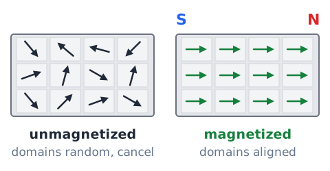
Inside iron, nickel, cobalt, and some alloys, atoms act like tiny magnets, and neighboring atoms tend to line up in groups called magnetic domains. In an ordinary iron nail, the domains point in random directions, so their effects cancel and the nail is not magnetized.
When a strong field is applied, domains aligned with it grow and others turn. In a permanent magnet, special alloys keep most domains aligned after the outside field is removed. Strong heating or repeated hard impacts can scramble the domains again and weaken the magnet.
Which materials magnets attract
Strong attraction to an ordinary magnet happens mainly with ferromagnetic materials: iron, most steels, nickel, cobalt, and certain alloys. A steel paper clip, a nail, or a screwdriver blade will jump toward a magnet because the magnet temporarily aligns domains in them.
Many good electrical conductors are not attracted in any noticeable way. Copper wire, aluminum foil, brass, gold, wood, plastic, glass, and paper show essentially no pull. Being a conductor and being magnetic are different properties, so do not assume a metal will stick just because it carries current well.
Current creates a circular magnetic field
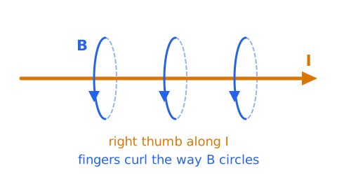
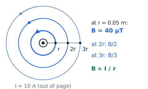
Any wire carrying current is wrapped in a magnetic field. For a long straight wire the field lines are circles centered on the wire, lying in planes perpendicular to it. A compass held beside the wire points along those circles, not toward or away from the wire.
The right-hand grip rule gives the direction. Point your right thumb along the conventional current, from positive toward negative, and curl your fingers around the wire; your fingers show the direction the field circulates. Reverse the current and the circulation reverses too.
Dot and cross notation for current
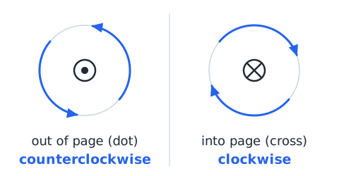
Diagrams often show a wire end-on. A dot inside a circle means current is coming out of the page toward you, like the point of an arrow approaching. A cross (an x) inside a circle means current is going into the page, like the tail feathers of an arrow moving away.
Apply the grip rule. With your thumb pointing out of the page, your fingers curl counterclockwise as you look at the page. With your thumb pointing into the page, they curl clockwise. Memorize the pair: dot gives counterclockwise, cross gives clockwise.
What controls the field around a wire
For a long straight wire, the field strength at distance r is
where I is the current in amperes, r is the distance from the wire in meters, and
Field is proportional to current and inversely proportional to distance. For example, 10 A at 0.05 m gives
T, or 40 microtesla. Doubling I doubles B; tripling r cuts B to one third.
Magnetic field from a current loop
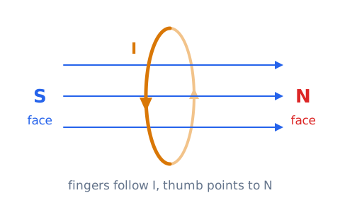
Bend a straight wire into a circle and the circular field lines from every small piece of the wire all pass through the middle of the loop in the same direction. The field inside the loop is therefore concentrated, and the loop behaves like a very short bar magnet with one face acting as N and the other as S.
To find which face is north, curl the fingers of your right hand in the direction the conventional current flows around the loop. Your thumb points through the loop toward the north face. Reversing the current swaps the two faces.
Solenoid: many turns, one controllable magnet
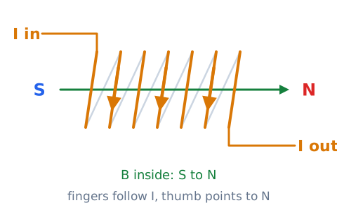
A solenoid is a wire wound into a long coil of many closely spaced turns. The fields of all the loops add together. Inside the coil the field is strong and nearly uniform along its length; outside it looks much like the field of a bar magnet.
The right-hand coil rule finds the poles: wrap your fingers around the coil in the direction of conventional current and your thumb points to the N end. A solenoid is an electromagnet, so switching the current off removes most of the field, and reversing the current reverses which end is north.
Ampere-turns and coil strength
The magnetizing strength of a coil depends on two numbers multiplied together: the number of turns N and the current I. Their product, , is called ampere-turns. A coil of 300 turns carrying 0.2 A gives 60 ampere-turns, exactly the same magnetizing effect as 30 turns carrying 2 A, as long as the coil size and core are the same.
So there are two ways to strengthen an electromagnet without changing its core: add turns or raise the current. Ampere-turns are not volts or watts; they are a measure of magnetizing force.
Iron cores and field concentration
Placing a soft iron rod inside a coil makes the electromagnet many times stronger. The coil's field aligns the iron's domains, and the magnetized iron adds its own field to the coil's. The result is a much higher flux density in and near the core for the same current.
Soft iron is chosen because its domains line up easily and also relax easily when the current stops, so the magnet turns off cleanly. Hard steel would keep some magnetism. A core of wood or plastic adds essentially nothing. The core does not supply energy; the coil current must still flow.
Electromagnet versus permanent magnet
A permanent magnet holds its field with no power supply, but you cannot easily switch it off or adjust it. An electromagnet is a coil, usually with an iron core, whose field exists only while current flows through it.
That gives the electromagnet three advantages: it can be turned on and off, its strength can be adjusted by changing the current, and its poles can be flipped by reversing the current. Both kinds have a north and a south pole and both attract iron. Scrapyard lifting magnets, door locks, and relays use electromagnets for this control.
Relay function and isolation
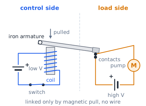
A relay is an electrically operated switch. A small current through its coil turns the coil into an electromagnet, which pulls a hinged iron armature. The armature moves a set of contacts that open or close a completely separate circuit.
The key benefits are control and isolation. A low-voltage, low-current signal, such as from a thermostat or a small control circuit, can switch a heavy load like a pump motor. The control side and the load side are connected only by the magnetic pull, not by wire, so the two circuits can operate at very different voltages.
Why a relay coil needs transient control
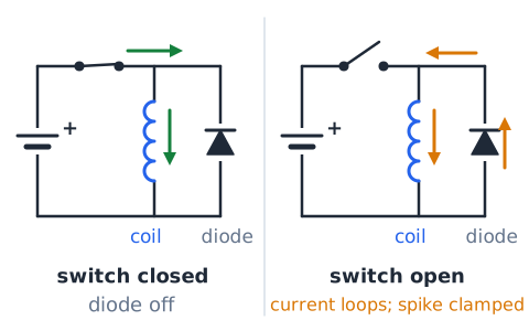
A relay coil stores energy in its magnetic field while current flows. When the driving switch opens, the current tries to drop to zero almost instantly. The coil resists that sudden change and produces a brief voltage spike that can be many times the supply voltage.
That spike can arc across switch contacts or destroy a transistor driving the coil. A common fix is a diode placed across the coil, pointing so it does not conduct normally. When the switch opens, the diode gives the coil current a safe loop to die away in, clamping the spike.
Inductance: opposition to current change
Inductance, symbol L, measures how strongly a coil opposes a change in its current. Its unit is the henry (H). The voltage that appears across an inductor is
where is how fast the current changes, in amperes per second. A steady current produces no inductive voltage. For example, a 0.3 H coil whose current rises at 20 A/s develops
a voltage that pushes against the change.
Inductive energy storage
An inductor stores energy in its magnetic field, the way a capacitor stores energy in an electric field. The stored energy is
with W in joules, L in henries, and I in amperes. A 0.1 H coil carrying 2 A holds
Because current is squared, doubling the current makes four times the energy. This stored energy is released when the current falls, which explains switching spikes. A resistor, by contrast, stores nothing; it only turns energy into heat.
Magnetic force on a moving charge
A charge moving through a magnetic field feels a sideways push given by
where q is the charge in coulombs, v the speed in m/s, B the field in teslas, and the angle between the velocity and the field. The force is largest when the charge moves straight across the field and zero when it moves along the field. A charge at rest feels no magnetic force at all. Example: C at 500 m/s across 0.4 T feels N.
Force on current-carrying conductor
A current is many moving charges, so a wire carrying current in a field feels a force:
Here is the length of wire inside the field in meters and is the angle between the wire and the field. For a wire straight across the field,
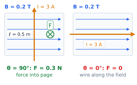
Example: 0.2 T, 3 A, and 0.5 m give 0.3 N. A wire running parallel to the field has
and feels no force.
Force direction is not field direction
Students often assume a wire is pushed along the field lines. It is not. The magnetic force is always perpendicular to both the current and the field. If the field points to the right across a page and the current runs up the page, the force points either into or out of the page.
One way to find it is the right-hand palm rule: point your fingers along the field, your thumb along the conventional current, and the force comes out of your palm. On the test, first make sure the answer is perpendicular to both; that often eliminates most choices.
Why a motor can turn
Put a rectangular loop of wire in a magnetic field and send current through it. The current flows one way along one side and the opposite way along the other side, so the two sides are pushed in opposite directions. Two equal, opposite forces on opposite sides of an axle create a twist, called torque, and the loop rotates.
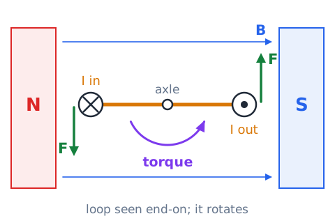
Left alone, the loop would stop once its plane faces across the field. A motor keeps turning by reversing the loop current at the right moment each half turn, so the torque keeps acting in the same rotational direction.
Magnetic flux: field through area
Magnetic flux measures how much field passes through a surface:
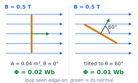
where B is in teslas, A is the area in square meters, and is the angle between the field and the line perpendicular to the surface. The unit is the weber (Wb), equal to one tesla times one square meter. A 0.5 T field straight through a 0.04 m^2 loop gives 0.02 Wb. Tilt the loop to 60 degrees and the flux halves to 0.01 Wb. Do not mix up tesla (field) with weber (flux).
How induction produces an emf
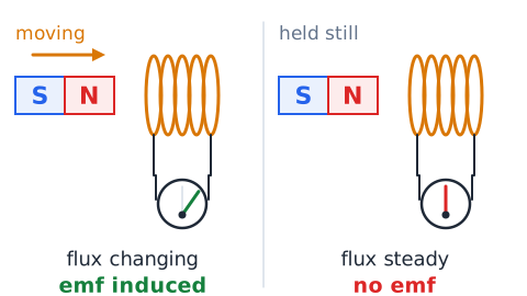
Electromagnetic induction is the creation of a voltage, called an electromotive force or emf, whenever the magnetic flux through a circuit changes. The flux can change in three ways: the field strength changes, the area of the loop inside the field changes, or the loop turns so its angle to the field changes.
What matters is change, not the presence of a field. A coil sitting in a strong but steady field has no induced emf. If the circuit is closed, the induced emf drives an induced current. This principle runs generators, transformers, and many sensors.
Faraday law: rate matters
Faraday's law gives the size of the average induced emf:
N is the number of turns, the change in flux through each turn in webers, and the time in seconds. A 100-turn coil whose flux changes by 0.003 Wb in 0.06 s produces 5 V. The same flux change made three times faster gives three times the emf; doubling the turns doubles it. A minus sign is often written to show the emf opposes the change.
Lenz law prevents free energy
Lenz's law gives the direction of an induced current: it always flows so that its own magnetic field opposes the change in flux that caused it. If flux through a loop is increasing, the induced field points the opposite way to reduce the gain. If flux is decreasing, the induced field points the same way as the original to prop it up.
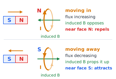
This is energy conservation at work. If the induced current helped the change instead, it would speed itself up and create energy from nothing. Because it resists, someone must do work, such as pushing a magnet, to get electrical energy out.
Move magnet in and out of a coil
Connect a coil to a sensitive meter and push the N end of a bar magnet into it. The meter needle kicks one way while the magnet moves, then returns to zero when the magnet stops. Pull the magnet back out and the needle kicks the opposite way.
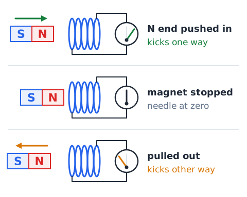
Each observation follows the rules. Motion changes the flux, so an emf appears only during motion. Moving in increases flux and moving out decreases it, so the directions are opposite. Moving faster gives a larger kick, and using more turns of wire also increases the reading.
A magnet held still cannot power a lamp indefinitely
Suppose a strong magnet is taped inside a coil connected to a small lamp. The lamp stays dark. The flux through the coil is large, but it is not changing, so Faraday's law gives zero emf.
To keep the lamp lit, something must keep the flux changing: spinning the magnet, moving the coil, or feeding an alternating current to a nearby coil. Each method requires an outside energy source. A stationary magnet is not a fuel and cannot act as a permanent battery; any claim of steady power from a still magnet is false.
What an AC transformer relies on
A transformer has two coils wound on a shared iron core with no wire connecting them. Alternating current in the input coil creates a magnetic flux in the core that rises, falls, and reverses many times each second. That constantly changing flux passes through the output coil and induces an alternating voltage there.
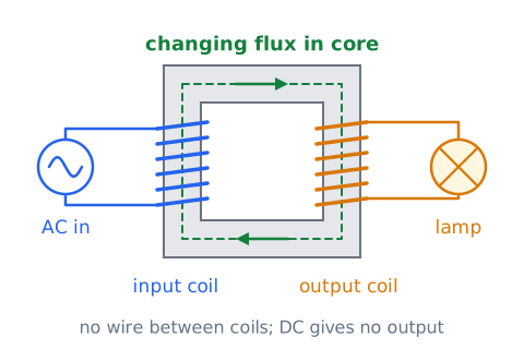
Because the method depends on changing flux, a transformer works with AC but not with steady DC. A constant DC current gives a constant flux, so after the first instant no voltage is induced in the output coil. The next lesson covers turns ratios in detail.
Generator versus motor in one sentence
A motor takes electrical energy in and gives mechanical motion out, using the force on a current in a field; a generator takes mechanical motion in and gives electrical energy out, using induction.
The two machines are built from the same parts: coils, magnets, and a rotating shaft. In fact, many motors will act as generators if their shaft is spun by an outside force. On a test, decide which way energy is flowing. If a turbine, engine, or hand crank drives the shaft and a lamp lights, the device is a generator. If a battery drives a fan, it is a motor.
Eddy currents are induced loops in metal
Induction does not need a coil of wire. When the flux through a solid piece of metal changes, the emf drives swirling loops of current inside the metal itself, called eddy currents. By Lenz's law these currents oppose the change.
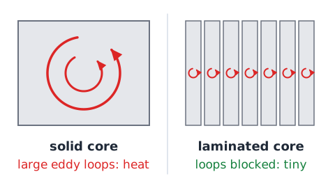
Eddy currents have useful and harmful effects. They produce the braking force on a metal disk spinning between magnets, as in some train brakes, and they heat the pan on an induction cooktop. In transformer and motor cores they waste energy as heat, so cores are built from thin insulated sheets, called laminations, to block the loops.
Ferromagnetism, permeability and saturation
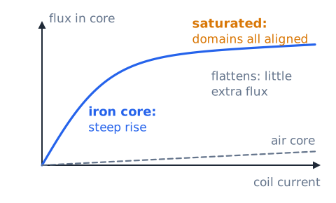
Ferromagnetic materials such as iron become strongly magnetized in an applied field. Permeability describes how easily a material supports magnetic flux. Soft iron has a permeability hundreds or thousands of times that of air, which is why an iron core makes a coil so much stronger.
That boost has a limit. Once nearly all the domains in the core are aligned, the core is saturated. Further increases in coil current then add only a small amount of extra flux, about what an air core would give. Designers size cores so normal operation stays below saturation.
Hysteresis versus reluctance
Two terms are easy to mix up. Reluctance is the opposition a magnetic path offers to flux, much as resistance opposes current in a circuit. A long air gap has high reluctance; a short, thick iron path has low reluctance.
Hysteresis is the lag of a material's magnetization behind the field that drives it. When the field is removed, some magnetism remains; when the field reverses, extra effort is needed to flip the domains. In AC cores, every cycle repeats this process and loses a little energy as heat, which is called hysteresis loss.
DC coil behavior during switching
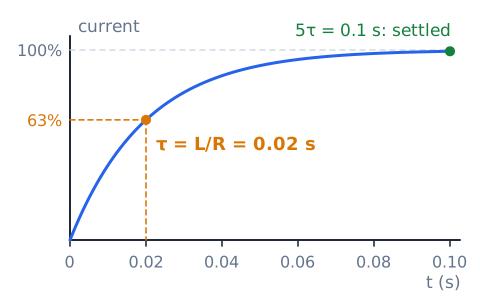
When DC voltage is applied to a coil with resistance R and inductance L, current does not jump instantly to V/R. It rises along a curve set by the time constant
in seconds, with L in henries and R in ohms. After one the current reaches about 63 percent of its final value, and after about five it is essentially complete. A 0.5 H coil with 25 has
so it settles in about 0.1 s. Once steady, the coil acts like a plain resistance.
Distinguish electromagnet from induction
These two ideas both involve coils and magnetism, but they run in opposite directions. An electromagnet uses current to make a magnetic field: send current through a coil and it becomes a magnet. The field exists as long as the current flows, even if nothing changes.
Induction uses a changing magnetic field to make a voltage: change the flux through a coil and an emf appears. A steady field induces nothing. When a question describes current producing attraction, think electromagnet. When it describes motion or changing flux producing voltage, think induction.
Current direction versus electron movement
By long-standing convention, current direction is the way positive charge would move, from the positive terminal through the circuit to the negative terminal. In metal wires, the moving charges are actually electrons, which drift the opposite way, from negative to positive.
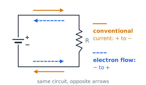
Both descriptions give the same magnetic field, as long as you use the matching rule. The right-hand rules in this lesson assume conventional current. Some training materials use electron flow with left-hand rules instead. On the test, check which convention the question uses, then apply the matching hand.
Units and formulas at a glance
Keep units straight and many questions answer themselves. Magnetic flux density B is in teslas (T). Magnetic flux is in webers (Wb), and one weber equals one tesla times one square meter. Inductance L is in henries (H). Induced emf is in volts, force in newtons, energy in joules, and the time constant in seconds.
The core relations are for a wire,
Conserving energy in electromagnetic devices
No magnetic device creates energy. An electromagnet uses electrical energy from its supply, much of it turned into heat in the coil resistance. A generator turns mechanical work into electrical energy, and by Lenz's law it gets harder to turn as more current is drawn. A transformer can raise voltage, but only by lowering current, so power out never exceeds power in.
Real devices lose some energy as heat in wires, eddy currents, and hysteresis, so their efficiency is below 100 percent. Treat any answer choice promising more energy out than in as wrong.
ASVAB direction-question procedure
Direction questions become routine with a fixed procedure. Step one: identify what is given, such as current direction, field direction, or a change in flux. Step two: confirm the convention; assume conventional current unless the question says electron flow. Step three: pick the matching rule, the grip rule for the field around a wire or coil, the palm rule for force, or Lenz's law for induced current. Step four: physically use your hand and trace the answer before reading the choices.
Finally, check that a force answer is perpendicular to both current and field.
Safety and non-practical experiment boundary
This lesson is about understanding, not hands-on testing of real equipment. Strong magnets can pinch skin or shatter when they snap together, and they can damage watches, credit cards, and some medical implants. Coils connected to supplies can get hot and can produce sudden voltage spikes when switched off.
Never experiment on household wiring, power tools, microwave ovens, or vehicle ignition systems, which carry dangerous voltages and stored energy. Simple demonstrations with a compass and a small battery-powered coil are enough. Leave real electrical work to trained, qualified people following proper safety procedures.
Exam map: what belongs in the next lesson
This lesson covers the foundation: poles, fields, the field of a current, electromagnets, force on wires, flux, Faraday's law, Lenz's law, and inductance. The next lesson applies those ideas to complete machines.
There you will meet motors in more detail, including commutators and back emf; generators, including AC output and frequency from pole count and speed; and transformers, including turns ratio, current ratio, power balance, and efficiency. If a question here asks only whether a changing flux makes voltage, it belongs to this lesson; if it asks for a transformer's output voltage, practice it in the next one.
Example 1 — Like and unlike poles
Problem: Two bar magnets lie end to end. Magnet A has its S end facing magnet B's S end. Then magnet B is flipped around. What happens each time?
Step 1: S facing S means like poles, so they repel.
Step 2: After flipping B, A's S end faces B's N end. Unlike poles attract.
Answer: they first push apart, then pull together.
Example 2 — Current out of the page
Problem: A wire seen end-on is marked with a dot. A compass sits directly to the right of the wire. Which way does its needle point?
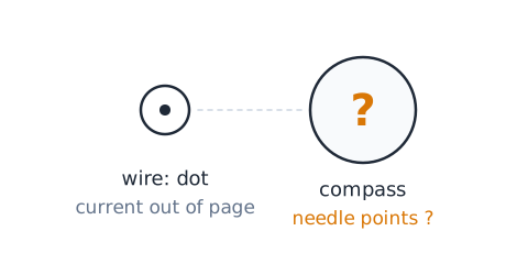
Step 1: A dot means current comes toward you. The grip rule gives a counterclockwise field.
Step 2: Going counterclockwise, at the right side of a circle the motion is upward.
Answer: the needle's N end points up the page.
Example 3 — Double the current
Problem: A long wire carrying 5 A produces 40 microtesla at a sensor. The current is raised to 10 A; the sensor does not move. What is the new field?
Step 1: at a fixed distance.
Step 2: The current doubled, so B doubles:
Answer: 80 microtesla.
Example 4 — Double the distance
Problem: A long wire produces 30 microtesla at 2 cm. With the same current, what is the field at 4 cm?
Step 1: , so the field is inversely proportional to distance.
Step 2: The distance doubled, so the field halves:
Answer: 15 microtesla.
Example 5 — Compare ampere-turns
Problem: Coil A has 200 turns carrying 0.5 A. Coil B has 50 turns carrying 3 A. Same size and core. Which magnetizes more strongly?
Step 1: Coil A:
ampere-turns.
Step 2: Coil B:
ampere-turns.
Answer: coil B is stronger, by a factor of 1.5, despite having fewer turns.
Example 6 — Perpendicular magnetic force
Problem: A 0.6 m wire carries 4 A straight across a 0.25 T field. Find the force.
Step 1: Perpendicular means
Answer:
Example 7 — Parallel wire makes no magnetic force
Problem: A 1.2 m wire carries 8 A in a 0.5 T field, but the wire runs exactly along the field lines. What force does it feel?
Step 1: The angle between wire and field is 0 degrees, and
Step 2:
Answer: zero newtons. Large numbers do not matter if the angle kills the force.
Example 8 — Flux perpendicular to a loop
Problem: A uniform 0.2 T field passes straight through a 0.05 m^2 loop. Find the flux.
Step 1: Field along the loop's normal, so
Answer:
Wb.
Example 9 — Flux when field lies in plane
Problem: The same 0.2 T field and 0.05 m^2 loop are turned so the field lines skim along the loop's surface. Find the flux.
Step 1: The field is now at 90 degrees to the normal, and
Answer: 0 Wb. No field lines pass through the loop, even though the field is still present.
Example 10 — Average induced voltage
Problem: A 50-turn coil's flux changes by 0.004 Wb per turn in 0.02 s. Find the average emf.
Step 1:
Wb/s.
Step 2:
Answer: 10 V.
Example 11 — Double the turns
Problem: In Example 10 the coil gave 10 V. The coil is rewound with 100 turns, and the same flux change happens in the same 0.02 s. What is the emf now?
Step 1: Emf is directly proportional to N when the per-turn flux change and time stay fixed.
Step 2: The turns doubled, from 50 to 100, so the emf doubles.
Answer: 20 V.
Example 12 — Lenz law with increasing field
Problem: A field pointing out of the page through a flat loop is getting stronger. Which way does the induced current circulate, viewed from the page?
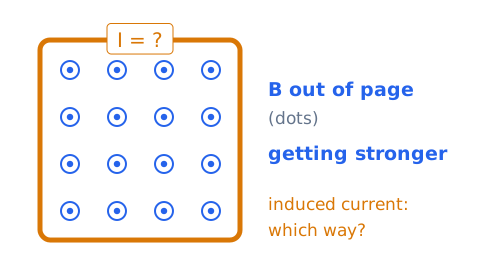
Step 1: The out-of-page flux is increasing, so the induced field must point into the page to oppose it.
Step 2: A field into the page inside a loop needs clockwise current, by the grip rule.
Answer: clockwise.
Example 13 — Magnetic energy in a coil
Problem: A 0.4 H inductor carries 5 A. How much energy is stored?
Step 1:
Answer:
Example 14 — RL time constant
Problem: A 0.2 H coil in series with 40 is connected to 12 V DC. Find the time constant and the current after one time constant.
Step 1:
or 5 ms.
Step 2: Final current is
after one it reaches about 63 percent.
Answer: 5 ms and about 0.19 A.
Drill 1 — Pole sorting
For each pair facing each other, decide attract or repel.
N facing N? Repel, like poles.
N facing S? Attract, unlike poles.
S facing S? Repel.
A magnet cut in half; the cut ends face each other as they were? Attract, since the cut created an S face and an N face side by side.
Drill 2 — Grip rule sketch
Give the field circulation viewed from the page.
Current out of the page (dot)? Counterclockwise.
Current into the page (cross)? Clockwise.
Current reversed in the second wire? Counterclockwise.
A dot wire with a compass directly above it; needle points? Left, because counterclockwise motion at the top of a circle goes leftward.
Drill 3 — Compare solenoids
Coil A: 400 turns at 0.25 A. Coil B: 100 turns at 2 A. Same length and core.
Ampere-turns for A?
Ampere-turns for B?
Which is stronger and by how much? Coil B, twice as strong.
Drill 4 — Force and angle
Use B = 0.5 T, I = 2 A, = 0.3 m.
At 90 degrees? 0.3 N.
At 30 degrees? Half that, 0.15 N, since
At 0 degrees? 0 N.
Drill 5 — Flux and induction
A 0.8 T field crosses a 0.02 m^2 loop squarely.
Flux?
Wb.
A 25-turn coil of this loop loses all its flux in 0.04 s. Average emf?
Same change over 0.08 s? 5 V.
Drill 6 — Device and safety classification
Name the main principle.
A relay pulling its armature? Electromagnet.
A bicycle dynamo lighting a lamp? Induction, a generator.
A diode across a relay coil? Spike suppression from inductive energy.
A strong magnet held still in a coil? No induced emf.
Opening a live microwave oven to look at its coil? Unsafe; never.
Reliable four-step EI method
Use the same four steps on every magnetism problem. First, classify the question: pole interaction, field direction, force, flux, induced emf, or stored energy. Second, write the one matching relation or hand rule before touching numbers. Third, check the angle or change: a parallel wire has no force, a field in the plane of a loop gives no flux, and a steady flux induces no emf. Fourth, scale or compute, then sanity-check units: teslas for B, webers for flux, volts for emf, joules for energy.
Many items are ratio questions; find what doubled or tripled and scale instead of computing from scratch.
Frequent ASVAB traps and corrections
Trap: believing cutting a magnet isolates a pole. Fix: each piece gets both poles.
Trap: thinking copper or aluminum sticks to magnets. Fix: strong attraction is mainly iron, steel, nickel, and cobalt.
Trap: placing the force along the field. Fix: magnetic force is perpendicular to both field and current.
Trap: expecting voltage from a strong but steady field. Fix: only changing flux induces emf.
Trap: confusing tesla with weber. Fix: tesla is field, weber is field times area.
Trap: forgetting the square in . Fix: doubling current gives four times the energy.
Trap: using electron flow with right-hand rules. Fix: right hand goes with conventional current.
Mastery checklist and formula sheet
You should now be able to state that like poles repel and unlike attract, that field lines run N to S outside a magnet, and that closer lines mean a stronger field. You should know a current makes a circular field (dot gives counterclockwise, cross gives clockwise), that coils with iron cores make controllable electromagnets, and that ampere-turns set coil strength. You should recognize that induction requires changing flux and that Lenz's law makes the induced effect oppose the change.
Formula sheet:
 English ▾