 ASVAB Camp
Lesson goal and safety boundary
By the end of this lesson you should be able to recognize common electrical hazards, explain what fuses, circuit breakers, GFCIs, AFCIs and grounding conductors each do, and reason through open-circuit, short-circuit, leakage and overcurrent problems using simple schematics, Ohm's law and power formulas.
Everything in this lesson happens on paper. It is general safety education for the ASVAB Electronics Information test, not training to inspect, test or repair real wiring. Work on live or possibly energized equipment belongs to qualified people who follow approved procedures and use properly rated tools and protective gear.
Start with electrical risk, not with a repair
When a question describes a damaged cord, a buzzing outlet or a tripped breaker, the first issue is not how to fix it but whether someone could get hurt. Electrical energy injures people through shock, burns and fire, often before anyone notices a problem.
A sound first response is to stop using the item, keep people away and report it. For example, if a toaster cord feels hot and smells like melting plastic, the safe answer is to stop using the toaster and have it checked or replaced, not to open it up and look for the loose wire. Repairs come later, and only from qualified people.
Electric shock is current through a body
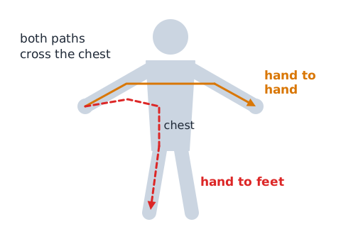
An electric shock happens when part of the body becomes part of a circuit, so current enters at one point and leaves at another. Voltage provides the push, but the harm depends mainly on how much current flows, the path it takes and how long it lasts.
A path from one hand to the other, or from a hand to the feet, crosses the chest and can upset the heart's rhythm. Currents of only a few tens of milliamperes can be dangerous. Touching a single conductor is not automatically safe, because the body may complete a path to ground.
Distinguish electric shock, arc, and thermal hazards
Electrical hazards come in more than one form. Shock is injury from current passing through the body. An arc is current jumping through the air between conductors or from a conductor to ground; an arc flash releases intense light and heat, and an arc blast can throw molten metal and create a pressure wave.
Thermal hazards come from heat: an overloaded cord, a loose terminal or an overheated motor can burn skin or ignite nearby material. One fault can create more than one hazard at once, so read the scenario closely before naming the hazard.
Why contact conditions matter
Ohm's law,
explains why the conditions at the point of contact matter so much. Dry, unbroken skin has fairly high resistance, which limits current. Wet or broken skin, sweat, standing water, metal jewelry and a conductive floor all lower the resistance, so the same voltage can drive far more current through the body.
Larger contact area and firmer contact also lower resistance. Since none of these can be judged safely by feel, treat any answer that calls a voltage safe because the hands are dry with suspicion.
De-energized is a verified condition
Flipping a switch or seeing a lamp go dark does not prove a circuit is dead. A switch may interrupt only one conductor, a panel label may be wrong, a circuit may be fed from two places, and stored energy may remain inside equipment.
In professional practice, de-energized is a condition that qualified workers establish and then confirm with approved procedures and properly rated test equipment before anyone touches conductors. On the exam, treat a statement such as "the light is off, so the wires are safe" as an assumption, not a fact.
Identify all energy sources conceptually
Equipment can receive or hold energy from several places at once. Besides the main supply there may be a backup battery, an uninterruptible power supply, a solar panel, a generator, a second feed, charged capacitors, a spinning motor or flywheel, a compressed spring or pressurized fluid.
Safe planning starts by listing every possible source on paper. A schematic that shows a battery backup next to a wall supply is testing whether you notice that removing one source leaves the other one in place.
Lockout and tagout are more than a label
Lockout/tagout is a workplace control program that OSHA requires when many kinds of machines are serviced. A lockout device physically holds an energy-isolating device, such as a disconnect switch, in the off position, usually with a padlock controlled by the worker. A tag is a warning sign; it communicates but cannot physically stop anyone from restoring power.
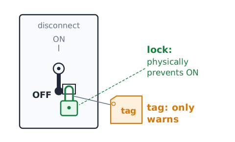
A complete program includes written procedures, training, isolation of every energy source, release of stored energy and verification. A tag alone is weaker protection than a lock plus a tag.
Capacitors may retain energy after unplugging
A capacitor stores energy in the electric field between its plates, and it can hold that charge after a device is unplugged. Power supplies, camera flashes, microwave ovens and motor-start circuits can contain capacitors large enough to injure. The ideal stored energy is
where E is energy in joules, C is capacitance in farads and V is voltage in volts. Because voltage is squared, tripling the voltage stores nine times the energy. Discharging capacitors is a job for qualified personnel.
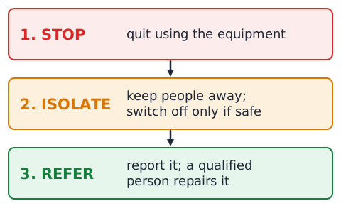
Use the STOP–ISOLATE–REFER decision model
A simple way to organize safety questions is STOP, ISOLATE, REFER. STOP means quit using the equipment as soon as you notice a hazard such as heat, smoke, sparks or exposed wiring. ISOLATE means keep people away and, only where it can be done without touching damaged parts, disconnect power at a switch or breaker. REFER means report the problem and let a qualified person evaluate and repair it.
This model is a study aid, not a procedure for doing electrical work. On the test, an answer that follows this order usually beats one that improvises a repair.
Know what an insulator does
An insulator is a material with very high resistance, such as rubber, most plastics, glass, ceramic or dry air. Insulation on a wire keeps current inside the conductor and keeps people and other conductors from touching it.
Insulation has limits. It is rated for a maximum voltage and temperature, and it can crack, melt, be cut or absorb moisture. Once it is damaged, its protection is gone. Tape over a break is not an approved repair; the cord should be removed from service and properly repaired or replaced.
A protective earth is not a normal load conductor
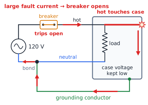
A protective earth, also called an equipment grounding conductor, connects exposed metal parts, such as an appliance case, to the grounding system. Under normal conditions it carries essentially no current.
If a fault lets a hot conductor touch the case, the grounding conductor gives the fault current a low-resistance path back to the source. The resulting large current helps a fuse or breaker open quickly and limits how high the case voltage can rise. It is a safety path for faults, not a normal return for load current, and it does not make every contact harmless.
Neutral and grounding conductors serve different roles
A typical 120 V household branch circuit has three conductors. The hot, or ungrounded, conductor carries current to the load. The neutral, or grounded conductor, carries the normal return current back to the source, so it is part of the working circuit. The equipment grounding conductor, often bare or green, normally carries no current and serves only as a fault path.
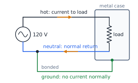
Neutral and ground are bonded together at the main service, but they are not interchangeable in branch wiring. Removing the grounding pin from a plug defeats the fault path.
Double insulation is a design protection
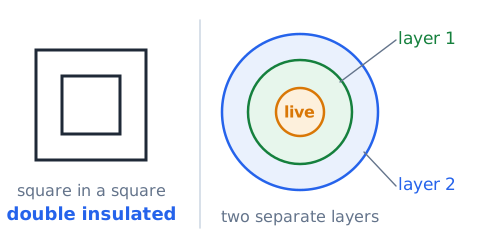
Some tools and appliances have two-prong plugs because they are double insulated. Instead of relying on a grounding conductor, the design surrounds live parts with two independent layers of insulation, or one reinforced layer, often inside a plastic housing. If one layer fails, the other still separates the user from live parts.
Such products are commonly marked with a square inside a square. Double insulation is a design feature, not a reason to ignore a cracked housing or damaged cord; physical damage can defeat both layers.
Overcurrent is current above a circuit limit
Overcurrent is any current larger than the rating of a conductor or piece of equipment. Heating in a wire rises quickly with current, because the power turned into heat in a resistance is
with P in watts, I in amperes and R in ohms. Doubling the current through the same resistance produces four times the heat. A wire rated for 15 A that carries 25 A can get hot enough to damage insulation and start a fire. Protective devices are sized to stop overcurrent before the wire is harmed.
Distinguish overload from short circuit
Two kinds of overcurrent are easy to confuse. An overload happens when properly connected loads simply draw more current than the circuit is rated for, such as a space heater, hair dryer and kettle all running on one branch. Current is moderately above the rating, and heat builds gradually.
A short circuit happens when current finds an unintended low-resistance path, such as two conductors touching, so current can leap to many times its normal value almost instantly. A ground fault is a related case in which the unintended path leads to ground or grounded metal.
Fuses interrupt excessive current
A fuse is a protective device with a metal link that melts when current stays above its rating long enough. When the link melts, the circuit opens and current stops. A standard fuse works once and must be replaced with one of the same type and rating.
Fuses are rated in amperes for the current they carry, in volts for the voltage they can safely interrupt, and by timing, such as fast-acting or time-delay. A fuse protects wiring and equipment from overcurrent; it is not designed to protect a person from a small shock current.
Circuit breakers can interrupt a fault
A circuit breaker does the same basic job as a fuse but can be reset after it trips. Inside, a thermal element, often a bimetal strip, bends in response to a sustained overload, while a magnetic element reacts almost instantly to the very large current of a short circuit. Either one releases a mechanism that snaps the contacts open.
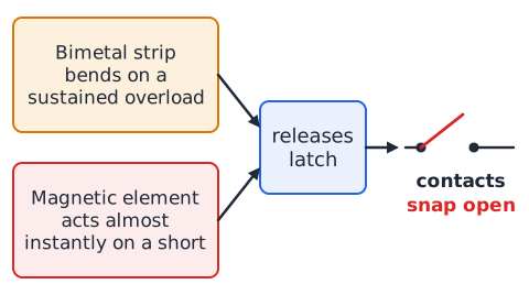
After a trip, the cause should be found before the breaker is reset. A breaker that trips again and again is signaling a problem; replacing it with a larger one or holding it closed removes the protection the wiring depends on.
A GFCI addresses a different fault
A ground-fault circuit interrupter, or GFCI, compares the current leaving on the hot conductor with the current returning on the neutral. Normally the two are equal. If some current escapes through another path, such as through a person to ground, they differ. When the difference reaches roughly 4 to 6 milliamperes, the GFCI opens the circuit within a fraction of a second.
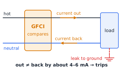
GFCIs are required in places such as bathrooms, kitchens, garages and outdoor outlets. A GFCI does not limit total current, and it cannot sense a hot-to-neutral path through a person, because that current still returns on the neutral.
AFCI and GFCI are not identical
An arc-fault circuit interrupter, or AFCI, watches the current waveform for patterns that signal dangerous arcing, such as a frayed cord or a loose connection sparking inside a wall. Its main purpose is preventing fires.
A GFCI, in contrast, looks for current leaking to ground and mainly protects people from shock. A fuse or standard breaker responds to too much current. Combination devices exist, but each function answers a different question: too much current, current leaking away, or arcing. Exam items often check whether you can match the device to its hazard.
Why a fuse cannot fix a damaged cord
A fuse responds only to how much current flows. A cord with cracked insulation may carry a perfectly normal load current while exposing a live conductor to anyone who touches it. The fuse sees nothing unusual and stays intact.
A person touching that conductor might carry only tens of milliamperes, far below a 15 A fuse rating yet enough to cause injury. Protective devices reduce some risks; they cannot repair physical damage. A damaged cord must come out of service.
Recognize symptoms, not proof
Symptoms point toward possibilities; they rarely prove a cause. A dark lamp could mean a burned-out bulb, an open switch, a broken wire, a tripped breaker or a lost supply. A warm outlet cover could mean a loose terminal, an overloaded receptacle or a nearby heat source.
Good reasoning lists the causes that fit the evidence, checks which ones explain every observation, and identifies what further information would separate them. On the ASVAB, prefer answer choices that say a cause may be present over choices that claim certainty from one clue.
The basic fault families
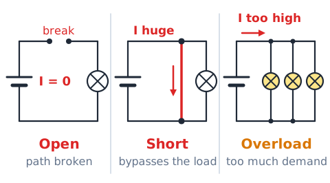
Most circuit faults fall into a few families. An open is a break in the path, so current stops. A short is an unintended low-resistance path, so current rises and may bypass a load. A ground fault is an unintended path to ground or grounded metal. Leakage is a small unwanted current through damaged or damp insulation.
A high-resistance connection is a poor joint that limits current and creates local heat. An overload is too much demand on a correctly wired circuit. Naming the family is often the first step toward the right answer.
Open circuit in a series path
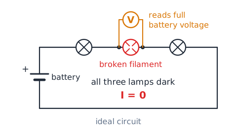
In a series circuit, all components sit in a single loop, so the same current flows through each of them. If any connection opens, the loop is broken and current drops to zero everywhere.
Picture a battery feeding three lamps in a row: if one filament breaks, all three go dark. The battery still has its voltage. In an ideal circuit the full source voltage appears across the open gap, because with no current there is no voltage drop across the other parts. An open circuit can still have voltage present.
Open circuit in one parallel branch
In a parallel circuit, each branch connects directly across the source, so each branch has the full source voltage and its own current. If one branch opens, only that branch stops. The others keep the same voltage and the same current as before.
Total source current falls by the amount the open branch used to carry. For example, a 24 V supply feeding a 6 Ω branch and a 12 Ω branch delivers 4 A plus 2 A, or 6 A in total. If the 12 Ω branch opens, the total falls to 4 A.
A short circuit can bypass a load
A short circuit across a load gives current an easier path around it. Because the short has almost no resistance, nearly all current takes that path and the load receives little or none, so a shorted lamp goes dark.
Meanwhile, total circuit resistance drops sharply, and source current can rise to a very high level limited only by wiring and source resistance. That large current produces heat quickly, and it is exactly what fuses and breakers are designed to interrupt. In most respects a short is the opposite of an open.
High-resistance contacts can heat
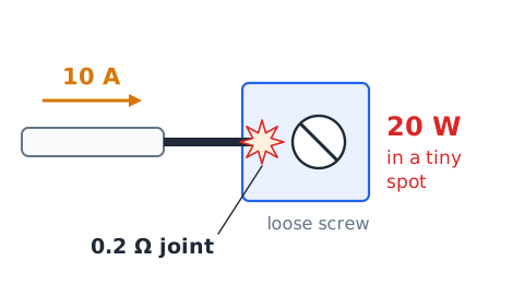
A loose screw terminal, a corroded connector or a worn plug blade can add unwanted resistance where current squeezes through a small contact area. The current is set mostly by the load, so the heat produced at the joint follows
Suppose 10 A of load current passes a joint with 0.2 Ω. The joint dissipates
W concentrated in a tiny spot, enough to discolor plastic and start a fire. Because circuit current stays normal, a breaker may never trip.
Why lights dim when voltage falls
For a resistive load such as a heater or incandescent lamp, power depends on voltage this way:
If resistance stays constant and voltage drops, power drops by the square of the voltage ratio. A heater that makes 1,000 W at 120 V would make only
W at 108 V, which is 90 percent of normal voltage. Lamps dim for the same reason. Real filaments change resistance with temperature, so the ideal model is an approximation.
Voltage drop is across an element
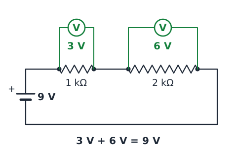
Voltage is always measured between two points. A voltage drop is the difference in electric potential across one component or one length of wire. Around a series loop, the drops add up to the source voltage, as Kirchhoff's voltage law states.
For instance, a 9 V battery driving a 1 kΩ and a 2 kΩ resistor in series puts 3 V across the first and 6 V across the second. Saying "the voltage at the resistor" is incomplete; the meaningful statement is the voltage across it, or between two named points.
An ammeter is not a voltmeter
An ammeter measures current, so it must be placed in series, letting the circuit current pass through it. It has very low internal resistance so that it barely changes the circuit. A voltmeter measures the potential difference between two points, so it is connected in parallel across them, and it has very high resistance so it draws almost no current.
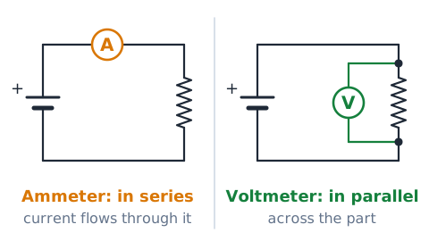
Connecting an ammeter directly across a voltage source would create a near short circuit. On the test, match the instrument to the quantity and to the correct connection.
Proper meter rating matters
Test meters and their leads are designed for limited voltages and particular environments. Many carry a measurement category rating, such as CAT II, CAT III or CAT IV, together with a voltage, describing how well they withstand voltage spikes in different parts of an electrical system.
Cracked probes, worn lead insulation, the wrong internal fuse or an incorrect setting can turn a meter into a hazard. A cheap or "digital" meter is not automatically safe. The meter, leads and accessories must suit the circuit and be used by trained people.
Continuity versus resistance
A continuity check asks a yes-or-no question: is there an unbroken path between two points? Many meters beep when the resistance is below a small threshold. A resistance measurement gives a number in ohms, such as 47 Ω for a resistor or 0.3 Ω for a short length of wire.
Continuity is useful for finding an open fuse or a broken conductor; resistance tells how much opposition is present. Both functions work by having the meter push its own small current through the part, so both are done only with circuit power removed.
Do not measure ohms on live power
An ohmmeter finds resistance by sending a small, known current from its internal battery and measuring the resulting voltage. If the circuit already has an outside voltage on it, that voltage corrupts the reading and can drive current into the meter, damaging it or endangering the user.
Resistance readings are therefore taken only on circuits that are de-energized and isolated, with any capacitors already discharged. A zero or odd reading taken on an energized circuit proves nothing about safety.
Read schematic symbols before conclusions
Schematic questions depend on reading symbols correctly. A zigzag line or small rectangle is a resistor, a pair of parallel lines of unequal length is a cell, a circle with a cross inside is often a lamp, a line hinged away from a contact is an open switch, and stacked horizontal lines mark a ground.
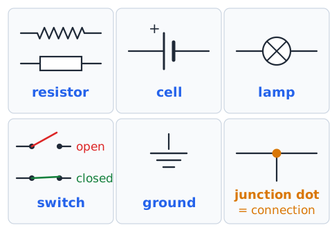
Before drawing conclusions, trace each path from the source and back, note whether every switch is drawn open or closed, and label series and parallel groups. Many wrong answers come from misreading a switch position or overlooking a junction dot.
Instrument readings are evidence with uncertainty
Every measurement has limits. Meter accuracy is stated as a percentage plus a few digits, probes can make poor contact, and readings can shift with temperature or a loose connection. A reading of 118 V instead of 120 V is usually normal variation, not proof of a fault.
A single strange reading should be confirmed and weighed alongside other evidence. In exam problems, use the ideal values given in the question; do not invent extra error unless the question supplies it.
A systematic paper-only diagnostic method
For schematic troubleshooting on paper, work in a steady order. First, identify the source and its voltage. Next, trace the complete path and classify each part as series or parallel. Then list the observations: which loads work and which do not.
After that, list the fault types that would explain every observation, and use Ohm's law or the power formulas to test each one. Finally, choose the explanation that fits all of the evidence with the fewest extra assumptions.
Use elimination rather than guesswork
Elimination means ruling out causes that conflict with the evidence. Suppose a schematic shows three lamps in parallel on one battery, and only the middle lamp is dark.
The battery cannot be dead, because two lamps still light. A short across the battery is unlikely, since it would pull the supply down and affect every lamp. What remains is a problem confined to that one branch, such as an open filament, an open switch or a break in the branch wiring. Elimination narrows the list without guessing.
Power calculation helps interpret heat
Power tells how fast electrical energy turns into heat or other forms. Three equivalent forms are useful:
Choose the form that uses what you know. A wire with 0.5 Ω carrying 4 A converts
W into heat along its length. Energy is power times time, so 8 W for 100 s is 800 J.
Understand safe equipment load ratings
Cords, outlets, power strips and branch circuits carry current ratings, and appliances list watts or amperes. To check whether loads fit, convert with
A 1,500 W heater on a 120 V circuit draws 12.5 A. Adding a 1,200 W microwave on the same circuit adds 10 A, for 22.5 A, well above a 15 A or 20 A branch. A light-duty extension cord rated at 10 A would be overloaded by the heater alone. Ratings are limits, not targets.
Why extension-cord damage matters
Extension cords are meant for temporary use, and they take abuse from being stepped on, pinched in doors, run under rugs and left coiled while carrying heavy loads. Any of these can crack insulation, break strands of the conductor or loosen the plug.
Broken strands reduce the copper cross section and raise resistance, creating hot spots. A cord under a rug cannot shed heat and hides damage. A cord that is crushed, cut, scorched or showing inner wires should be taken out of use at once.
Water changes the risk analysis
Water changes electrical risk in several ways. Ordinary water contains dissolved minerals and conducts, so it can create unexpected current paths between conductors or to ground. Wet skin has much lower resistance than dry skin, letting a given voltage push more current through the body, and standing in water or on a damp floor adds a good path to ground.
That is why outlets near sinks, tubs and outdoors are GFCI protected, and why equipment that has been flooded should not be used until a qualified person has evaluated it.
Smoke, sparks, and burning odor are warning signs
Smoke, sparks, crackling or buzzing sounds, a burning or fishy odor, discolored outlet covers and warm switch plates all warn of overheating or arcing. They show energy going where it should not.
The safe reaction is to stop using the equipment, cut power only if it can be done safely at a switch or panel away from the hazard, keep people back and get qualified help. If there is fire, leave and call emergency services. Touching or opening the device to investigate is not a safe response.
Downed power lines require distance
A fallen power line may still be energized even if it is silent and not sparking. Current can spread through wet ground, fences and puddles, creating dangerous voltage differences across the ground surface.
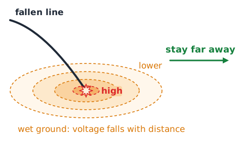
Stay far away, keep others back, and call 911 and the utility. Assume anything the line touches is energized too. If a line falls on a vehicle you are in, the general advice is to stay inside unless fire forces you out, and wait for the utility to make the line safe.
Electrical injury response prioritizes rescuer safety
If someone is in contact with an energized conductor, a bystander who grabs them can become a second victim, because current can flow into the rescuer too. The first priorities are to avoid touching the person or anything they are touching, call emergency services, and have power shut off by a safe means, such as a main switch, if that can be done without exposure.
Once the scene is safe, trained responders can give care. Electrical injuries can cause hidden internal burns and heart rhythm problems, so medical evaluation is needed.
A stopped motor might still be hazardous
A motor that is not turning is not necessarily safe. It may be stopped by its control circuit while its supply remains live, waiting for a timer, pressure switch or thermostat to restart it. It may contain start or run capacitors that hold a charge.
A large motor that is coasting down still has mechanical energy, and a spinning motor can act as a generator. Automatically controlled equipment can start without warning. This is why isolating and locking out every energy source comes before any service work.
A tripped GFCI is not proof of a short
When a GFCI trips, it has detected a difference between outgoing and returning current, typically just a few milliamperes. That points toward leakage to ground, which could come from moisture in an outdoor outlet, damaged insulation in a tool, or a genuine ground fault.
It does not prove a line-to-neutral short, which a GFCI is not built to sense. Nuisance trips also happen. A trip is evidence of a possible ground-fault path that needs qualified evaluation.
A correctly sized fuse is not an optional accessory
A fuse is sized to protect the wiring and equipment after it. Replacing a blown fuse with a larger one, a coin or a piece of wire removes that protection, because the circuit can then carry enough current to overheat conductors with nothing to open it.
The original fuse blew for a reason, such as an overload or short, and that cause is still there. Treat the fuse rating as a required part of the design: same type, same rating, and only after the cause is corrected.
Voltage ratings and current ratings differ
Components carry separate ratings, and each describes a different limit. A voltage rating tells how much potential difference the insulation or device can safely withstand or interrupt. A current rating tells how much current it can carry without overheating.
A fuse marked 250 V and 5 A, for example, may be used on circuits up to 250 V, carries up to 5 A normally, and opens when current stays well above that. A higher voltage rating does not allow more current, and a high current rating does not permit a higher voltage.
Understand low voltage without false confidence
Low-voltage sources, such as a 12 V car battery or a 9 V battery, rarely push dangerous current through dry skin. That does not make them harmless. A car battery can deliver hundreds of amperes into a short, heating a wrench or a ring red-hot within seconds and causing severe burns.
Batteries can also vent flammable hydrogen, and low-voltage parts may sit next to higher-voltage circuits or be fed from a converter. Treat "low voltage" as lower shock risk, not zero risk.
Interpret ground symbols cautiously
Schematics use several ground symbols. Stacked lines that get shorter usually mean earth ground, a connection to the earth or the building grounding system. A chassis ground symbol shows connection to a metal frame. A signal or common ground marks the reference point for voltages in a circuit and may not connect to earth at all.
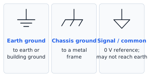
Because 0 V at a reference point is a definition, not a guarantee, a part marked "ground" on a drawing is not proof that the matching point in real equipment is safe to touch.
Protective device limitations are exam traps
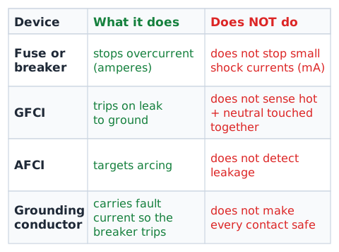
Test writers like answer choices that overstate what a device can do. A fuse or breaker protects wiring from overcurrent, but it does not stop small shock currents. A GFCI protects against many ground-fault shocks, but not against touching hot and neutral together, and it does not replace sound insulation.
An AFCI targets arcing, not leakage. A grounding conductor helps faults clear but does not make every contact safe. Watch for words like always, every and guarantees.
ASVAB strategy for safety questions
Electronics Information safety questions usually reward the most cautious correct choice. When options include improvising a repair, defeating a protective device or touching something to check it, eliminate them. Prefer answers that stop the hazard, keep people clear and refer the work to qualified personnel.
For definition questions, match each device to its specific job. For calculation questions, write the formula first, include units and check that the result is reasonable. Read carefully for words such as series, parallel, ideal and constant.
Close with a safe engineering mindset
People who work safely around electricity share a few habits. They assume a circuit is energized until the right people with the right tools have proved otherwise. They treat protective devices as part of the design rather than obstacles. They keep observations separate from conclusions and look for evidence before blaming a part, and they know the limits of their training and ask for help.
On the test, that mindset means choosing answers that protect people first, reason from evidence second and fix equipment last, and only through qualified hands.
Example 1 — fuse versus GFCI
Scenario: A hair dryer with damaged insulation falls into a filled sink, and about 20 mA flows from it through the water to a grounded metal drain. The circuit has a 20 A breaker and a GFCI receptacle. Which device is expected to respond?
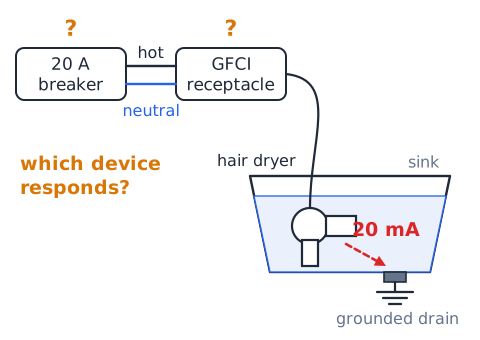
Step 1: Compare the leakage with the breaker rating. 20 mA is 0.02 A, a tiny fraction of 20 A, so the breaker sees no overcurrent.
Step 2: Compare outgoing and returning current. About 20 mA leaves on the hot conductor but never returns on the neutral, an imbalance far above the GFCI trip level.
Answer: the GFCI is the device designed to respond.
Example 2 — resistive heating rises with current
Problem: A 0.3 Ω connection carries 5 A. If current rises to 15 A, how does its heating change?
The current tripled, so heating grew by
times. Answer: from 7.5 W to 67.5 W, nine times as much.
Example 3 — an open series path
Problem: A 9 V battery drives 1 Ω, 2 Ω and 6 Ω resistors in series. Find the current, then the current after a lead of the 2 Ω resistor breaks open.
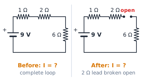
Before the break, total resistance is 9 Ω, so
After the break there is no complete loop, so current is 0 A in every part, and in the ideal model the full 9 V appears across the gap. Answer: 1 A before, 0 A after.
Example 4 — a branch failure in parallel
Problem: A 12 V source feeds three parallel lamps of 6 Ω, 12 Ω and 24 Ω. The 12 Ω lamp opens. Find total current before and after.
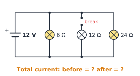
Before:
After:
The working lamps keep 12 V and the same current. Answer: total current drops from 3.5 A to 2.5 A.
Example 5 — power at a poor connection
Problem: A 15 A load current passes through a corroded plug blade with 0.1 Ω of contact resistance. Find the heat released there and the voltage lost.
Answer: 22.5 W of heat in a small area and a 1.5 V drop, leaving slightly less voltage for the load.
Example 6 — calculate load current
Problem: A 120 V branch has a 15 A breaker and powers a 900 W coffee maker and a 600 W toaster. Is it overloaded?
Answer: 12.5 A is below 15 A, so the circuit is within its rating. Adding a 1,000 W kettle would add about 8.3 A, for roughly 20.8 A, which would be an overload.
Example 7 — contrast GFCI and breaker
Scenario A: A worn cord lets the hot and neutral conductors touch, and current jumps to hundreds of amperes. Scenario B: A wet drill leaks 15 mA through the user's hand to a grounded pipe.
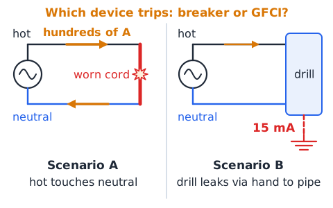
In A, the current is huge but returns on the neutral, so the breaker's magnetic trip opens the circuit. In B, the current is far too small for a breaker, but it does not return on the neutral, so a GFCI trips.
Answer: the breaker handles A; the GFCI handles B.
Example 8 — stored capacitor energy
Problem: An unplugged power supply contains a 2,000 μF capacitor still charged to 100 V. Find its ideal stored energy.
Convert:
F.
Answer: 10 J, stored with no supply connected.
Example 9 — identify a likely open branch
Scenario: A schematic shows a 6 V battery and closed switch S1 feeding three parallel branches. Branch A has lamp L1, branch B has switch S2 drawn open and lamp L2, and branch C has lamp L3. L1 and L3 glow; L2 is dark.
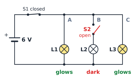
Reasoning: The source and S1 must work, since two lamps light. The drawing itself shows S2 open, which fully explains the dark lamp.
Answer: S2 being open is the justified cause; no failed part has to be assumed.
Example 10 — current and resistance trend
Problem: A 24 V source drives one resistor. Find the current for 12 Ω, 6 Ω and 3 Ω.
At 12 Ω:
At 6 Ω:
At 3 Ω:
Answer: 2 A, 4 A and 8 A. Each halving of resistance doubles the current, which is why a near-zero-resistance short draws such large current.
Example 11 — compare two contact losses
Problem: Joint M has 0.05 Ω and joint N has 0.2 Ω. Both carry 8 A. Compare their heating.
With equal current, heating is proportional to resistance, and 0.2 is four times 0.05. Answer: N heats four times as much as M.
Example 12 — why meter modes differ
Scenario: A paper plan proposes measuring a lamp's current by touching the leads across the lamp with the meter set to amperes, and measuring a resistor in a powered circuit on the ohms setting.
Analysis: In current mode the meter has very low resistance, so placing it across a component creates a near short that can blow the meter fuse or cause an arc; current is measured in series. In ohms mode the meter supplies its own current, so outside voltage gives false readings or damage.
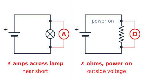
Conclusion: both plans are wrong.
Example 13 — battery and source power
Problem: A 12 V battery supplies 2 A to a radio. Find the power and the energy used in 10 minutes.
Answer: 24 W and 14,400 J, using 600 s for 10 minutes.
Example 14 — check a claimed root cause
Claim: "The breaker tripped, so the new microwave must have a short."
Check: A trip shows that a protective event occurred. Possible causes include an overload from several appliances on one circuit, a short in any connected device, a wiring fault or a worn breaker. The claim picks one cause without evidence ruling out the others.
Better conclusion: stop using the circuit, note what was running, and have a qualified person evaluate it before re-energizing. The microwave is a suspect, not a proven cause.
Drill 1 — name the protection
Name the protection designed for each situation.
Prompt: Too many heaters keep a circuit above its rating. Answer: fuse or circuit breaker.
Prompt: A few milliamperes leak from a tool through a user to ground. Answer: GFCI.
Prompt: A loose wire in a wall sparks repeatedly. Answer: AFCI.
Prompt: A fault energizes a metal case. Answer: the equipment grounding conductor, which helps the fuse or breaker open.
Drill 2 — identify an open
Prompt: A series string of four lamps is completely dark, though the battery is shown as good. Answer: an open somewhere in the single loop.
Prompt: One of three parallel lamps is out and the others are normal. Answer: an open in that one branch, such as a failed lamp or broken lead.
Prompt: Every parallel lamp is dark. Answer: a fault shared by all branches, such as the source or main feed.
Drill 3 — classify a reported symptom
Prompt: A breaker trips instantly with a loud snap when a lamp is plugged in. Answer: likely short circuit.
Prompt: A breaker trips after a heater runs for twenty minutes alongside other loads. Answer: likely overload.
Prompt: An outlet cover is discolored and warm. Answer: possible high-resistance connection; stop use and refer.
Drill 4 — compute power without field testing
Prompt: 3 A through 4 Ω. Answer:
Prompt: 10 V across 5 Ω. Answer:
Prompt: 120 V at 0.5 A. Answer:
Prompt: 2 A through 0.5 Ω. Answer: 2² × 0.5 = 2 W.
Drill 5 — choose the correct meter concept
Prompt: Measure current through a lamp. Answer: ammeter in series.
Prompt: Measure potential difference across a resistor. Answer: voltmeter in parallel.
Prompt: Check a removed fuse for an internal break. Answer: continuity or ohms on the de-energized fuse.
Prompt: Measure resistance at a live outlet. Answer: never; resistance is measured only de-energized.
Drill 6 — spot an unsafe distractor
Prompt: "Wrap the cracked cord in tape and keep using it." Answer: unsafe; remove the cord from service.
Prompt: "Swap the 15 A fuse for a 30 A fuse so it stops blowing." Answer: unsafe; it defeats overcurrent protection.
Prompt: "Pull the shocked worker away by the arm." Answer: unsafe; avoid contact and call for help.
Prompt: "It is unplugged, so the capacitor is safe." Answer: unsafe assumption.
Safety-first EI problem solving
Approach Electronics Information safety items in three passes. First, eliminate any choice that bypasses a protective device, touches energized parts, improvises a repair or assumes something is dead without verification.
Second, among the remaining choices, look for the one that matches a device or concept to its exact function, such as a GFCI to current imbalance or a fuse to overcurrent.
Third, for numeric items, write the relationship, such as
substitute with units and check the size of the result. Be wary of absolute words like always and guarantees, and favor answers that put people's safety ahead of keeping equipment running.
High-value mistakes to avoid
Mistake: treating a fuse or breaker as shock protection. Why it is wrong: these devices respond to amperes of overcurrent, while milliamperes can injure. Fix: link shock protection to GFCIs, insulation and grounding.
Mistake: assuming an open circuit has no voltage. Why it is wrong: source voltage can appear across the gap. Fix: say current is zero, not voltage.
Mistake: thinking doubled current doubles heating. Why it is wrong: heating follows . Fix: square the current ratio.
Mistake: calling the grounding conductor a normal return path. Fix: the neutral carries normal return current.
Quick review and safe boundaries
Electrical hazards include shock, arcs and heat. Shock severity depends on current, path and duration, and contact conditions change body resistance. De-energized is a verified state; capacitors, batteries and moving parts can hold energy after unplugging.
Fuses and breakers stop overcurrent, GFCIs detect current imbalance, AFCIs detect arcing, and the grounding conductor provides a fault path. An open stops current in a series loop or in one parallel branch; a short bypasses a load and raises current. Key formulas:
Stop, isolate and refer: testing and repairing real equipment belong to qualified personnel.
 English ▾