 ASVAB Camp
Learning objectives and reading rules
By the end of this lesson you should be able to look at a circuit diagram and name each part from its symbol: sources such as cells and batteries, resistors (fixed and variable), switches, lamps, fuses and breakers, capacitors, inductors and transformers, diodes and LEDs, transistors, ground marks, and meter circles.
You should also be able to read the conventions that tie the symbols together: lines are conductors, dots mark junctions, a crossing without a dot is usually not a connection, and labels such as R2 or C5 plus a value with units identify each part.
Reading rules for this lesson: trust the legend over habit, follow every complete loop from source and back, and treat every drawing as an idealized model unless the question says otherwise.
A schematic is a map of electrical relationships
A schematic does not show where parts sit on a circuit board or how big they are. It shows which terminals are electrically joined and in what order current can travel. Two resistors drawn far apart on the page may sit side by side on the real board, and a long drawn line may be a short trace.
Think of a subway map: it distorts distances but keeps stations and connections correct. A schematic does the same for electricity. When you read one, ask "what connects to what?" rather than "where is it?" That habit answers most ASVAB symbol questions.
Recognize three layers of a circuit diagram
Most circuit diagrams carry three layers of information. The first is the symbols themselves, which tell you the type of part: a zigzag for a resistor, two plates for a capacitor, a triangle and bar for a diode.
The second layer is the wiring: lines, dots and crossings that show which terminals share a node.
The third layer is text: reference designators such as R1, SW2 or D3, values such as 330 Ω or 10 µF, and notes on ratings or polarity. A strong reader checks all three before deciding what a part does. Skipping the text layer is a common reason for misreading a rectangle or a circle.
Conducting lines and wire bends
In a schematic, a plain line stands for an ideal conductor. It has no resistance, so every point along one unbroken line is at the same voltage. That set of joined points is called a node.
Lines bend at right angles purely for neatness. A corner does not add a part, a resistance, or a connection to anything else. If one wire runs up, turns right and then turns down to reach a lamp, it is electrically the same as a straight wire. Only symbols, dots, and explicit labels change the meaning; geometry and line length do not.
Connection dots mark intentional junctions
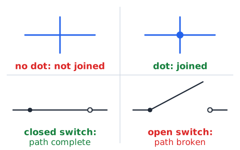
When three or more conductors meet and are meant to be joined, the drafter places a solid dot at the junction. The dot tells you every line touching it is one node. A T-shaped meeting of two lines is usually treated as joined even without a dot, but many drafters add the dot anyway for clarity.
The figure shows how a declared legend works: a crossing with a dot is a connection, and a plain crossing is not. It also shows switch contacts for comparison. When a drawing states its own legend, follow it, because the dot convention is the most direct evidence of an intended junction.
Crossings are not automatically connections
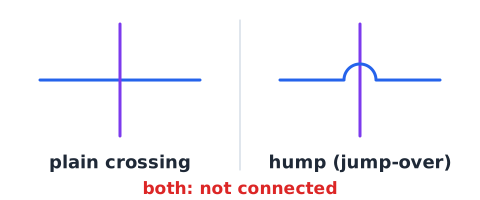
Wires on a schematic often have to pass over one another because the page is flat. Under the most common convention, two lines that cross with no dot are not connected; they simply pass by like a highway overpass.
Older drawings sometimes showed a small hump or loop where one wire jumps over another, which makes the "no connection" meaning obvious. Some drawings avoid plain crossings entirely and use dots or offsets. On an exam, if the question states the convention, apply it exactly. Never assume that a geometric intersection is an electrical node.
A battery is drawn as unequal parallel plates
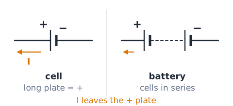
A single cell is drawn as two parallel lines of unequal length. The longer line is the positive terminal, and the shorter, often thicker, line is the negative terminal. A battery made of several cells in series is drawn as several such pairs, or as two pairs with a dashed line between them.
A plus sign is sometimes printed beside the long plate as a reminder. To remember the rule, picture the long line as a plus sign with its vertical stroke pulled tall. When you trace conventional current, it leaves the long (positive) plate, passes through the external circuit, and returns to the short plate.
A cell is one electrochemical unit
Strictly speaking, a cell is one electrochemical unit with a positive and a negative electrode, and a battery is a group of cells connected together. A common AA alkaline cell provides about 1.5 V, while a 9 V battery contains several smaller cells in series inside one case.
Everyday speech calls both "batteries," and many exam questions do too. The symbol shows the difference: one long-short pair means one cell, and repeated pairs mean a multi-cell battery. Either way, the symbol represents a source of voltage that pushes charge around a complete circuit.
A source is not the same as a load
Every working circuit needs at least one source and at least one load. A source, such as a cell, battery, or generator, supplies electrical energy. A load, such as a lamp, resistor, motor, or heater, converts that energy into light, heat, motion, or another useful form.
On a diagram, sources usually carry plus and minus marks or the long-short plate pattern. Loads usually do not. A common mistake is to call a lamp a source because it gives off energy; it only converts energy supplied to it. If there is no source in the loop, nothing in that loop will operate.
Know both common resistor drawings
Two resistor drawings are in common use. The US style shows a zigzag line, usually with three or four peaks. The international style, common in Europe and many datasheets, shows a small empty rectangle. Both mean the same part: a fixed resistor that opposes current and turns electrical energy into heat.
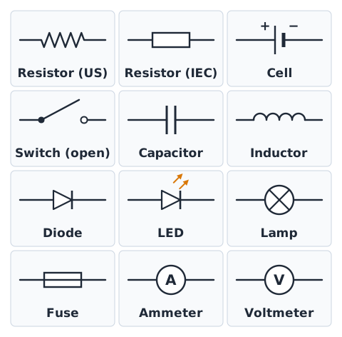
The figure gathers both resistor versions with other frequently tested symbols, including the cell, switch, capacitor, inductor, diode, LED, lamp, fuse and meter circles. Study it as a reference chart, and notice that the rectangle could be confused with a fuse unless you check its label.
Resistor labels and reference designators
Each resistor on a schematic gets a reference designator: the letter R followed by a number, such as R1, R2, R12. The number only identifies the part; it says nothing about its size. The value appears next to it with the ohm symbol and often a prefix.
So "R7 680 Ω" means resistor number seven has a nominal resistance of 680 ohms, and "R3 3.3 kΩ" means 3,300 ohms, because
Sometimes the letter replaces the decimal point: "4K7" means 4.7 kΩ.
Fixed versus variable resistor
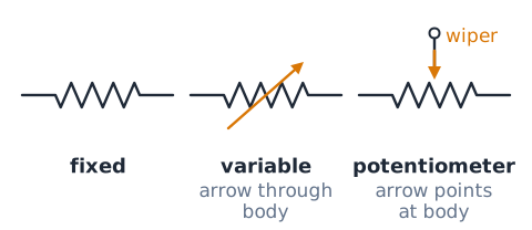
A fixed resistor has one set value. A variable resistor lets you change the resistance, and its symbol adds a diagonal arrow drawn through the zigzag or rectangle. A rheostat is a variable resistor used with two terminals to adjust current, such as an old lamp dimmer.
A potentiometer is a three-terminal version: two ends of a resistive track plus a movable wiper, drawn as an arrow pointing at the side of the resistor. A volume knob is a typical potentiometer. On an exam, the key clue is the arrow: through the body means variable, pointing at the body means a wiper contact.
A potentiometer can divide voltage
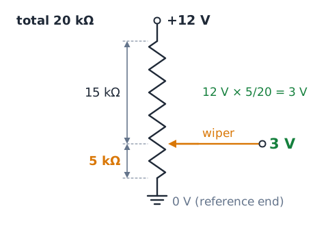
When a potentiometer's two ends are placed across a voltage, the wiper picks off a fraction of that voltage. For an unloaded pot, the wiper voltage measured from the reference end is
Here is the resistance between the wiper and the reference end. Example: a 20 kΩ pot across 12 V with its wiper 5 kΩ from the reference end gives 12 V times 5/20, or 3 V.
Switch symbols show the contacts
A switch symbol shows the contacts inside it. The usual drawing is a short line, the movable blade or lever, hinged at one terminal and angled away from a second terminal drawn as a small circle or dot. When the blade touches the second terminal, the path is complete.
Switches are labeled S or SW with a number, such as SW1. Some variations show a pushbutton with a small bar above the contacts or a toggle with a lever. Whatever the style, look at the contacts: where the conductive path is broken, current cannot pass, and where the contacts meet, the switch acts like a wire.
Open and closed states are functional
An open switch has its contacts apart, so it breaks the path and the current through that branch is zero. A closed switch has its contacts touching, so it acts like a short piece of wire with essentially no resistance.
These words describe the electrical function, not a door or a valve. People who think of water pipes sometimes reverse the meaning, because an "open" valve lets water flow. In electricity, open means no current through the switch, and closed means current can flow. Memorize it as "closed completes the circuit."
A pushbutton contact has a normal state
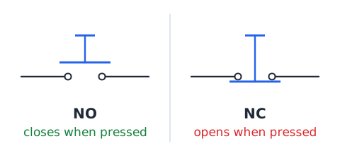
A pushbutton is a momentary switch that returns to its resting position when you let go. The resting position is called its normal state. A normally open (NO) button has contacts apart at rest and closes only while pressed, like a doorbell button. A normally closed (NC) button has contacts touching at rest and opens while pressed, like some emergency stop circuits.
Diagrams always draw a switch in its normal, unactuated state. So if a pushbutton appears closed on paper, it is an NC type, and pressing it will break the path.
SPST versus SPDT switches
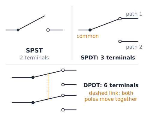
Switches are classified by poles and throws. A pole is a separate circuit that the switch controls; a throw is a position that completes a path. An SPST (single-pole, single-throw) switch is a plain on-off switch with two terminals.
An SPDT (single-pole, double-throw) switch has one movable common contact that connects to either of two fixed contacts, so it has three terminals. It can steer current to one of two paths, as in a pair of hallway switches controlling one light. A DPDT switch has two poles that move together, each with two throws, for six terminals in all.
A lamp is a load and an indicator
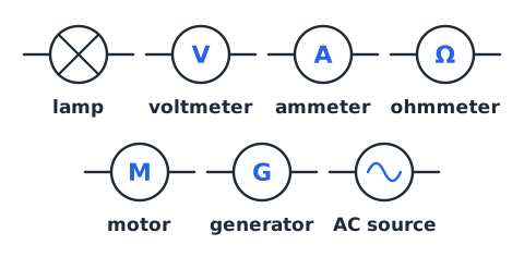
A lamp, or bulb, is a load: it converts electrical energy into light and heat. A common symbol is a circle with an X inside it, while some drawings use a circle containing a small loop that represents the filament.
Lamps also serve as indicators. If a lamp in a simple loop lights, you know a complete path exists and current is flowing. If it stays dark, the loop may be open somewhere, the source may be dead, or the lamp itself may have failed. On a schematic a lamp is usually labeled L, DS or LP followed by a number.
Distinguish lamp circle from meter circles
Several symbols are drawn as circles, so look at what is inside. A circle with an X (or a filament loop) is a lamp. A circle with the letter V is a voltmeter, A is an ammeter, and the Greek letter omega (Ω) is an ohmmeter. A circle with M is a motor, and a circle with G is a generator.
A circle with a sine-wave squiggle is an AC source. Mistaking a meter for a load, or a lamp for a meter, changes how you interpret the whole circuit, so read the letter first.
A fuse is a sacrificial protection element
A fuse is a protective device that contains a thin strip or wire designed to melt when current exceeds its rating for long enough. When it melts, the path opens and current stops, which protects wiring and equipment from overheating.
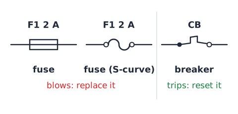
A fuse is sacrificial: once it blows, it must be replaced with one of the same rating. Common symbols are a small rectangle with a line running through it lengthwise, or a short S-shaped curve between two terminals. Fuses are labeled F with a number and a current rating, such as F1 2 A. They are placed in series with the circuit they protect.
An open fuse interrupts the intended path
When a fuse blows, its element is gone, and the fuse behaves like an open switch. In a simple series loop, that means current through every part in the loop drops to zero. The lamp goes dark, the motor stops.
It does not mean voltage disappears everywhere. The source is still there, and the full source voltage now appears across the gap in the open fuse. A blown fuse also points to a cause, such as a short or an overload, that should be found before replacing it. Installing a larger fuse to stop repeated blowing removes the protection and creates a fire risk.
A circuit breaker is resettable protection
A circuit breaker does the same basic job as a fuse: it interrupts the circuit when current is too high. The difference is that a breaker opens a mechanical contact instead of destroying a link, so after the cause is fixed it can be reset with a switch or button and used again.
Many breakers use a heat-sensitive strip that bends under a sustained overload and a magnetic coil that trips quickly on a large surge. Home electrical panels use breakers. The schematic symbol often looks like a switch with a small curved hook or a square bump on the blade, labeled CB.
A capacitor symbol has two plates
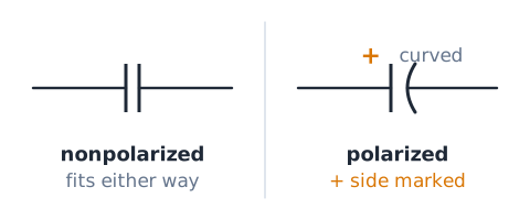
A capacitor is drawn as two parallel plates separated by a gap, with a lead coming out of each plate. The plates are usually the same length, which distinguishes them from a cell, where the lines are unequal and one is often thicker.
The gap represents an insulating material called the dielectric. The plates do not touch, so steady DC cannot pass through an ideal capacitor once it has charged. That gap is not a broken wire or an open switch, though: the plates are there to store charge and energy in an electric field. Capacitors are labeled C, as in C4 47 µF.
Capacitance is measured in farads
Capacitance tells how much charge a capacitor stores for each volt across it. Its unit is the farad (F), but one farad is huge, so practical values use microfarads (µF), nanofarads (nF), or picofarads (pF). The relationship is
Q is the charge on each plate in coulombs, C is capacitance in farads, and V is voltage in volts. A 100 µF capacitor charged to 9 V holds 900 µC on each plate.
Polarized capacitors require proper identification
Some capacitors, especially electrolytic types, are polarized: one lead must stay more positive than the other. The symbol shows this by curving one plate or drawing it as a filled bar, and by printing a plus sign next to the positive plate. The physical part usually has a stripe with minus signs on the negative side and a longer positive lead.
Connecting a polarized capacitor backward can make it overheat, leak, or even burst. Nonpolarized capacitors, such as most small ceramic types, use two straight plates and can be installed either way.
An inductor is drawn as a series of coils
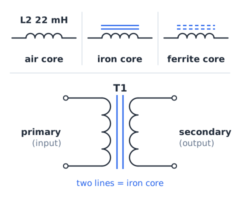
An inductor is a coil of wire, and its symbol shows a row of loops or bumps, usually three or four, like the coils of a spring. It is labeled L, as in L2 22 mH, and its unit is the henry (H).
If two or more parallel straight lines run alongside the coils, the inductor has an iron or steel core, which greatly increases its inductance. Dashed lines suggest a ferrite core. An inductor stores energy in the magnetic field produced by the current flowing through its coils. Do not confuse the inductor's loops with the zigzag of a resistor: one is smooth bumps, the other is sharp peaks.
Inductors resist changes in current
An inductor opposes changes in current. When current through it rises or falls, the coil's magnetic field changes and induces a voltage that pushes against the change. The size of that voltage is
L is inductance in henries, is the change in current in amperes, and is the time in seconds. A 50 mH coil whose current changes by 2 A in 0.01 s develops 10 V. With steady DC, the induced voltage is zero.
Transformers use two magnetically linked coils
A transformer is two or more coils sharing a magnetic path. Its symbol shows two inductor coils facing each other, usually with two parallel lines between them to indicate an iron core. The input coil is the primary and the output coil is the secondary.
An alternating current in the primary creates a changing magnetic field that induces a voltage in the secondary. If the secondary has more turns than the primary, it raises voltage (step-up); fewer turns lowers it (step-down). Transformers need changing current, so they do not pass steady DC. They are labeled T, as in T1.
A diode symbol marks directionality
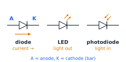
A diode is a one-way valve for current. Its symbol is a triangle pointing at a short straight bar, with a lead on each side. The triangle points in the direction conventional current flows easily, from the positive anode to the negative cathode.
When the anode is sufficiently more positive than the cathode, the diode is forward biased and conducts. When the polarity is reversed, it is reverse biased and blocks nearly all current. Diodes are labeled D, as in D1. Recognizing the arrowhead direction is the key skill, because it tells you which way the diode lets current pass in any loop.
Diode marking and the cathode bar
On the symbol, the straight bar across the triangle's point marks the cathode, and the flat side of the triangle marks the anode. On a real diode, a painted band or stripe around the body marks the cathode end, matching the bar in the drawing.
A memory aid: the bar looks like a wall that current runs into if it tries to go the wrong way, and the letter K is often used for the cathode on drawings. When you install or check a diode, line up the band with the bar on the schematic and the part will face the correct direction.
An LED symbol adds outward light arrows
A light-emitting diode is a diode that gives off light when it conducts. Its symbol is the normal diode symbol plus two small arrows pointing outward, away from the device, to show light leaving it.
A photodiode or other light sensor uses the reverse picture: the arrows point inward, toward the diode, showing light arriving. So outward arrows mean emitter, inward arrows mean detector. LEDs are often labeled LED1 or D2. Like other diodes, an LED only lights when it is forward biased, with its anode more positive than its cathode.
Forward bias and reverse bias are not labels of safety
Forward bias and reverse bias describe the polarity across a diode, not whether that condition is safe. A forward-biased diode conducts, but if nothing limits the current, it can overheat and fail in a moment. A reverse-biased diode blocks current, but if the reverse voltage exceeds its rating, it can break down and conduct heavily.
So forward is not automatically "good," and reverse is not automatically "off forever." Each diode has maximum ratings for forward current and reverse voltage. In circuit questions, look for a resistor or other part that sets the current, and check that the voltages stay within limits.
Zener and other special diode variants
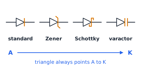
Special diodes keep the triangle-and-bar body but change the bar or add marks. A Zener diode has a bar with small bent tips, like a stretched Z; it is designed to conduct in reverse at a set voltage, which makes it useful as a voltage reference.
A Schottky diode has a bar with S-shaped hooks and is known for a low forward drop and fast switching. A varactor adds capacitor plates to the bar and acts as a voltage-controlled capacitor. In every case, the triangle still points from anode to cathode, so you can always find the direction even if you forget the variant's name.
Transistor symbols have three working terminals
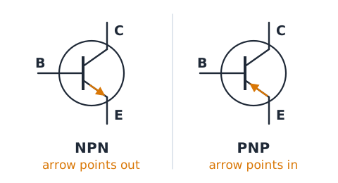
A transistor is a semiconductor part that can switch or amplify, and its symbol shows three terminals. A bipolar junction transistor (BJT) is drawn as a circle containing a vertical bar (the base) with two angled leads: the collector and the emitter. The emitter carries a small arrow.
If the arrow points out of the symbol, it is an NPN transistor; if it points in, it is PNP. A memory aid: NPN means "not pointing in." Field-effect transistors use different terminal names: gate, drain, and source. Transistors are labeled Q, as in Q1.
The ground symbol has more than one meaning
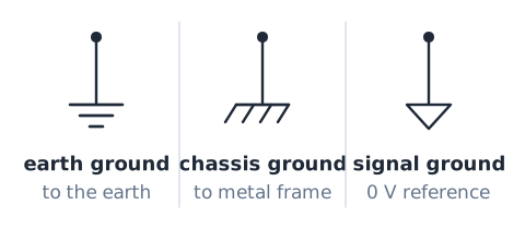
Several symbols mean "ground," and the word itself has more than one meaning. Earth ground, drawn as three horizontal lines that get shorter toward the bottom, is a real connection to the earth, used for safety in building wiring. Chassis ground, often drawn like a rake or comb, means a connection to a metal frame or case.
Signal or circuit ground, sometimes a plain open or filled triangle, is the common reference point for the circuit's voltages. In a battery-powered gadget, "ground" usually means the negative terminal or another chosen 0 V reference, with no link to the earth at all.
A reference ground does not consume current
When a circuit diagram marks a node as ground or 0 V, it is choosing a reference point for measuring voltages, much like choosing sea level for measuring altitude. Every ground symbol in that schematic is the same node, even if they are drawn far apart.
Ground is not a load and it does not soak up current. Current that flows into a ground symbol returns to the source through the shared return path. If a part connects to ground and to nothing else, no current flows through it, because there is no complete loop. A voltage at "5 V" simply means 5 V above the chosen reference node.
Ammeters and voltmeters carry different letters
Meters appear as circles with a letter that tells you what they measure. A circle with A is an ammeter, which measures current in amperes. A circle with V is a voltmeter, which measures voltage, or potential difference, in volts.
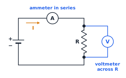
The figure shows a battery driving a resistor, with an ammeter placed in series so the loop current passes through it, and a voltmeter placed in parallel across the resistor's two ends. The meters are ideal: the ammeter has no resistance and the voltmeter draws no current, so adding them does not change the circuit.
An ohmmeter measures resistance only appropriately
An ohmmeter, drawn as a circle with the Greek letter omega (Ω), measures resistance. It works by sending its own small test current through the part and reading the resulting voltage. That is why it must be used on a component with the power removed.
If the circuit is still energized, the outside voltage corrupts the reading and can damage the meter. Also, parts connected in parallel with the one under test can give a misleading value, so technicians often lift one lead of a component before measuring it. An ohmmeter reading near zero suggests continuity; a very high reading suggests an open path.
A voltmeter is across the load
A voltmeter measures the difference in electrical potential between two points, so it is connected across a component, in parallel with it. To read the voltage drop across a lamp, one meter lead touches each lamp terminal; the circuit itself is not broken.
An ideal voltmeter has extremely high internal resistance, so it draws almost no current and does not disturb the circuit. If you wrongly put a voltmeter in series, its high resistance blocks most of the current, and the lamp will dim or go dark. On a schematic, look for the V circle drawn alongside the part with leads to both of its ends.
An ammeter is in the current path
An ammeter measures the current that flows through a path, so the path must be opened and the meter inserted into it, in series. All the current in that branch then passes through the meter.
An ideal ammeter has nearly zero resistance, so it adds almost nothing to the loop. That same low resistance is why connecting an ammeter across a source or across a part, in parallel, is a serious mistake: it creates a near short, and the large current can blow the meter's fuse or damage the source. On a schematic, the A circle sits directly in line with the wire carrying the current.
A voltmeter reading is always between two points
Voltage is always a difference between two points. A voltmeter needs two leads because it compares one point to another. If a question says "the voltage at node B is 4 V," it means 4 V relative to a reference, usually ground, even if the reference is not mentioned.
Touching only one lead to a circuit gives no meaningful reading. When you see a V circle on a diagram, find both ends of its connections. The meter reports the potential of the first point minus the potential of the second, so swapping leads on a digital meter simply reverses the sign of the reading.
Polarity marks versus current arrows
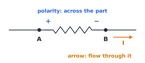
Plus and minus marks beside a part show which end is assumed to be at higher potential. The voltage between points A and B is written
If A is marked plus and the result is positive, A really is higher. A separate arrow along a wire, often labeled I, shows the assumed direction of current. The two marks are not the same: polarity describes potential across a part, and the arrow describes flow through it. If a calculation gives a negative value, the true direction is opposite to the assumed one.
Component letter codes are only conventions
Reference letters follow common conventions: R for resistor, C for capacitor, L for inductor, D for diode, Q for transistor, SW or S for switch, F for fuse, T for transformer, K or RY for relay, U or IC for an integrated circuit, and M for motor.
These letters are a drafting habit, not a law of physics. Some companies use different codes, and older drawings vary. When a letter seems out of place, check the drawing's parts list or legend. The symbol, value, and units together should agree with the letter.
Unit prefixes appear in component values
Component values use metric prefixes to avoid long strings of zeros. The common ones are mega (M, ), kilo (k, ), milli (m, ), micro (µ, ), nano (n, ), and pico (p, ).
So 1.5 MΩ is 1,500,000 Ω, 33 nF is 0.000000033 F, and 250 mA is 0.25 A. Watch the case: capital M means mega but lowercase m means milli.
An electronic symbol is not an internal photograph
A schematic symbol is a functional shorthand, not a picture of the part. A real resistor is a small cylinder with colored bands, not a zigzag. A real capacitor may be a tiny brown chip or a tall aluminum can, yet both use the two-plate symbol.
Likewise, one integrated circuit with dozens of pins may appear as a simple rectangle or as several separate gate symbols scattered across the page. Do not judge a part by how its symbol looks physically. Judge it by the standard meaning of the symbol, the reference designator, and the value printed beside it.
Trace the complete loop before predicting a lamp
Before you predict whether a lamp lights, trace a complete loop. Start at the positive terminal of the source, follow the conductors through each part, and see whether you can return to the negative terminal without lifting your finger.
Along the way, check every switch (open or closed?), every fuse (intact or blown?), and every diode (does it face the right way?). If any element in the only path is open, the lamp stays dark. If two paths exist, the lamp may still light through the other branch. This simple trace solves many diagram questions without any math.
A short circuit is a path, not a particular icon
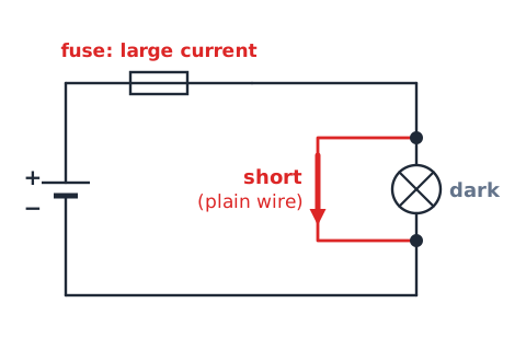
A short circuit is any unintended path with very low resistance between two points that normally have a voltage between them. There is no special "short" symbol. A short can be a plain wire drawn across a load, a closed switch placed in parallel with a lamp, or a failed part.
The danger is that current takes the easy path. A wire across a lamp starves the lamp, which goes dark, while the source may deliver a very large current through the shortcut. That large current is what fuses and breakers are designed to stop. Look for low-resistance paths around loads, not for an icon.
Series and parallel still matter in symbol quizzes
Symbol questions often hide a series-or-parallel question. In series, parts sit one after another on a single path, so the same current flows through each, and opening any one stops all of them. A string of holiday lights wired in series goes completely dark if one bulb fails.
In parallel, parts connect across the same two nodes, so each gets the same voltage and each branch has its own current. Opening one branch leaves the others working, which is why household outlets are wired in parallel. Recognize the arrangement first, then apply the symbol's behavior.
Capacitor and inductor symbols indicate stored fields
Capacitors and inductors both store energy, but in different fields. A capacitor stores energy in the electric field between its plates, and its symbol, two plates with a gap, suggests charge gathered on facing surfaces. An inductor stores energy in the magnetic field around its coils, and its symbol of loops suggests that coiled wire.
A memory aid: plates for electric charge, coils for magnetism. A capacitor resists sudden changes in voltage; an inductor resists sudden changes in current. Neither one is a source that runs a circuit on its own for long.
An LED indicator normally needs current control
An LED behaves differently from a lamp filament. Once its forward voltage is reached, a tiny increase in voltage can cause a large jump in current. Connected directly to a battery stronger than its rated voltage, an LED can draw far too much current and burn out quickly.
That is why indicator LEDs usually appear with a resistor in series. The resistor takes up the leftover voltage and sets a safe current, often around 10 to 20 mA for small indicators. When you see an LED and a resistor in one series path, read the resistor as the current-limiting part, not as decoration.
Recognize signal versus power symbols
Some diagrams mix power parts with signal parts. Power symbols include batteries, supply rails labeled such as +12 V or VCC, and heavy lines feeding motors or lamps. Signal parts carry small voltages that represent information, such as a microphone input, a sensor output, or a logic line labeled with a name.
A rail label like VCC means "connected to the positive supply," even if no wire is drawn to the battery. Arrow or flag shapes with names can show where a signal enters or leaves the page. Knowing which lines supply energy and which carry information helps you trace the circuit's purpose.
Read component legends and manufacturer notes
Many schematics include a legend, a notes block, or a parts list. These tell you how the drafter used symbols: whether crossings with no dot are connected, what a rectangle means, the tolerance of the resistors, voltage ratings of the capacitors, or which ground symbol is which.
Manufacturers also add notes such as "all resistors 1/4 W unless noted" or "capacitor values in µF." Reading the notes first prevents mistakes, especially with older or international drawings. On an exam, if a stem gives you a convention, treat it as the legend for that question and follow it even if your habit differs.
Why the circuit drawing order can mislead
Schematics are usually drawn with the source on the left and loads to the right, and with higher voltages near the top and ground at the bottom. That layout is a convenience, not a rule of electricity.
The risk is reading position as meaning. A part drawn first along the line is not "first" to receive current in any practical sense; current in a series loop is the same everywhere at once. A lamp drawn near the top is not brighter or more important. A part drawn far from the battery may still be directly across it. Trace connections, not page order, to understand how the circuit behaves.
A generic load box can hide internal complexity
Some diagrams draw a part as a simple box labeled LOAD, MODULE, or a part number. The box tells you that energy or a signal goes in and comes out, but it hides what is inside. It could be a simple heater or a complex circuit board.
Treat a generic box the way the question defines it. If the stem says the load acts like a 100 Ω resistor, use that. If it gives no details, do not invent internal behavior. Focus on what the external connections show: which nodes it touches, whether it is in series or parallel, and what source feeds it.
A motor and a generator have different roles
A motor and a generator are both drawn as circles, labeled M and G. Physically they can be nearly identical machines, but their roles are opposite. A motor is a load: it takes electrical energy and produces mechanical rotation, as in a fan or a drill.
A generator is a source: it takes mechanical rotation, such as from an engine or a turbine, and produces electrical energy. On an exam, decide which way energy flows. If the circle receives power from a battery to spin something, it is a motor. If it is driven by something and feeds the circuit, it is a generator.
A relay combines coil and contacts
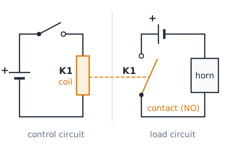
A relay is an electrically operated switch. Its symbol has two parts: a coil, drawn as a rectangle or a set of loops, and one or more switch contacts. A dashed line often links the coil to the contacts to show they act together. Both carry the same label, such as K1.
When current flows in the coil, its magnetic field pulls the contacts, closing a normally open contact or opening a normally closed one. The coil circuit and the contact circuit can be completely separate, so a small control current can switch a large load, such as a horn or a starter motor.
Overlapping wires are not proof of a short
When two lines overlap on a printed schematic, beginners sometimes assume they touch and form a short. That is not the case under the usual no-dot convention: a plain crossing means the conductors pass each other without contact.
A short exists only if there is an actual low-resistance connection, such as a junction dot, a drawn wire, or a stated fault, between points that should be separate. Before declaring a short, confirm the connection is real according to the drawing's convention. Then check whether the joined points normally have a voltage between them.
Resistor and fuse rectangles must have labels
The international resistor symbol is a plain rectangle, and some fuse symbols are also rectangles, sometimes with a line through the middle. Other standards use rectangles for generic loads, coils of relays, and heating elements.
Because the shape alone is not enough, a rectangle should always come with a reference letter and a value: "R5 1 kΩ" is a resistor, and "F2 500 mA" is a fuse. The unit is a strong clue too. Ohms point to a resistor, amperes with an F label point to a fuse. If a rectangle has no label, check the legend before deciding.
Putting the symbols together in one diagram
Picture a small flashlight-style circuit. A 6 V battery's long plate connects through a fuse F1, then a switch SW1, then splits at a junction dot into two parallel branches. One branch holds a lamp. The other holds an LED with a 220 Ω resistor in series, its triangle pointing away from the battery's positive side. Both branches rejoin and return to the short plate, which is marked as ground.
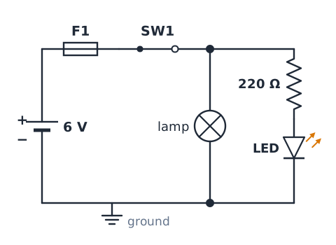
Reading it: the fuse protects everything, the switch controls both branches, the LED is forward biased, and its resistor limits current. Opening SW1 darkens both the lamp and the LED.
Safety is more than recognizing a fuse
Recognizing a fuse symbol is not the same as knowing a circuit is safe. A fuse protects wiring from overcurrent; it does not reliably protect a person from shock, because a dangerous current through the body can be much smaller than a fuse's rating.
Before working on real equipment, remove power, verify it is off with a meter you know works, and be aware that capacitors can hold a charge after power is removed. Never replace a fuse with a higher rating or a piece of wire. Ground-fault devices, insulation, and safe work habits are what protect people.
How exam questions use simplified icons
ASVAB electronics questions use simplified, idealized symbols. Wires have no resistance, switches are perfectly open or closed, meters do not disturb the circuit, and sources keep a constant voltage. Diode questions may give a fixed forward drop, such as 0.7 V, to keep math simple.
Do not overthink with real-world effects unless the question asks. If a stem says "ideal," use the ideal behavior. The test usually checks whether you can name a symbol, find the path, place a meter, or apply one formula, not whether you know every manufacturing detail.
Fast review of direction-sensitive symbols
Several symbols only make sense when you note their direction. The cell's long plate is positive. A diode's triangle points from anode to cathode, the way conventional current passes, and the bar is the cathode.
LED arrows point outward (light leaving); photodiode arrows point inward (light arriving). An NPN transistor's emitter arrow points out; a PNP arrow points in. Polarized capacitors show a plus sign on one plate. A current arrow shows an assumed direction. In each case, reversing the part changes how the circuit behaves.
How to handle an unfamiliar standard variant
Sooner or later you will meet a symbol that looks slightly different from the version you studied. Standards differ between countries and decades, and companies add their own styles.
When that happens, look for the family resemblance. A triangle with a bar is still some kind of diode. Plates are still a capacitor; coils are still an inductor. Then read the reference letter and the value with its units, which usually settle the question. If a legend is available, check it. On the test, choose the answer that matches the most evidence rather than the shape alone.
A compact schematic-reading checklist
Use this checklist to read any schematic. First, find the source and mark its positive and negative ends. Second, follow each line from the positive side and note every junction dot; treat plain crossings as unconnected unless told otherwise.
Third, name each symbol and confirm it with its letter and value. Fourth, check direction-sensitive parts: diodes, LEDs, transistors, and polarized capacitors. Fifth, check the state of every switch, fuse, and breaker. Sixth, decide which parts are in series and which are in parallel. Finally, answer what the question asks: path, part, meter, or value.
Example: two drawings of the same resistor
Problem: An American drawing shows "R2 470 Ω" as a zigzag. A European datasheet for the same circuit shows "R2 470 Ω" as a small empty rectangle. Are these different parts?
Step 1: Both have the same reference designator, R2. Step 2: Both have a value in ohms. Step 3: The zigzag and the empty rectangle are the two accepted resistor symbols.
Answer: They are the same fixed resistor, 470 ohms, drawn in two different standards.
Example: identify a battery terminal
Problem: A schematic shows a single cell with a long thin line on top and a short thick line on the bottom. Which terminal should connect to the red meter lead?
Step 1: In the cell symbol, the longer line is positive. Step 2: The red lead is the positive lead by convention.
Answer: Connect the red lead to the top terminal, the long plate. The short bottom plate is negative and takes the black lead.
Example: a switched lamp will not light
Problem: A diagram shows a 9 V battery, a closed fuse, a lamp, and a switch drawn with its lever angled away from the contact, all in one loop. Why is the lamp dark?
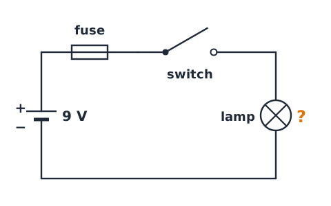
Step 1: Trace the loop from the positive plate. Step 2: The fuse is intact. Step 3: The switch lever does not touch its contact, so it is open.
Answer: The open switch breaks the only path, so the current is zero.
Example: check a symbol for a capacitor
Problem: A part has two equal parallel plates and the label "C3 47 µF." It sits across 6 V. Identify it and find the charge on each plate.
Step 1: Equal plates and the letter C mean a capacitor. Step 2: Use
Answer: It is a capacitor storing 282 µC.
Example: measure current at a branch
Problem: A 9 V source feeds two parallel branches. One branch is a 450 Ω resistor. Where should the ammeter go to read that branch, and what will it show?
Step 1: An ammeter goes in series inside the branch, between the junction and the resistor. Step 2: The branch has the full 9 V across it.
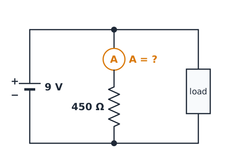
Answer: In series with the resistor, reading 20 mA.
Example: measure voltage across a resistor
Problem: A 24 V source drives a 2 kΩ resistor and a 4 kΩ resistor in series. Where does the voltmeter go, and what does it read across the 4 kΩ part?
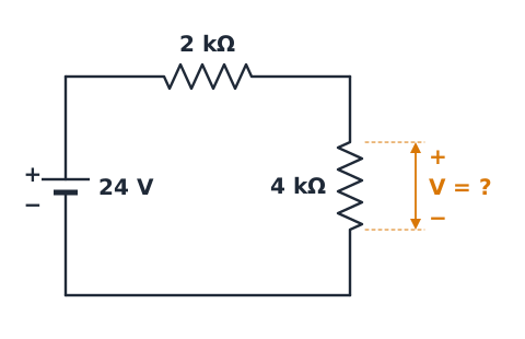
Step 1: Total resistance is 6 kΩ, so the current is 24 V divided by 6 kΩ, or 4 mA.
Answer: In parallel across the 4 kΩ resistor, reading 16 V.
Example: potentiometer midpoint
Problem: A 1 kΩ potentiometer has its two ends across a 5 V supply. The wiper is set exactly halfway along the track and nothing is connected to it. What is the wiper voltage relative to the grounded end?
Step 1: Halfway means 500 Ω below the wiper and 500 Ω above it.
Answer: 2.5 V.
Example: LED identification
Problem: A drawing shows a triangle pointing at a bar, with two small arrows leaving the symbol and pointing away from it. It is labeled D4. A nearby part has a similar diode with arrows pointing toward it. Name both.
Step 1: Triangle plus bar is a diode. Step 2: Outward arrows mean light is emitted. Step 3: Inward arrows mean light is received.
Answer: D4 is an LED; the other part is a photodiode (a light sensor).
Example: 2.2 kΩ means thousands
Problem: A resistor is marked 2.2 kΩ and has 11 V across it. Find the current.
Step 1: Convert: 2.2 kΩ = 2,200 Ω.
Answer: 5 mA. Forgetting the k would give 5 A, a thousand times too large.
Example: a protective element opens
Problem: A car accessory circuit has a 12 V battery, a 10 A fuse, a switch, and a motor in series. A wire inside the motor rubs through its insulation and touches the metal frame, which is grounded. The fuse blows. What happens to the motor current, and what should be done?
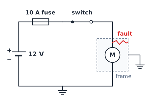
Step 1: The fault creates a low-resistance path, and current rises sharply. Step 2: The fuse opens, breaking the series loop.
Answer: Motor current falls to zero. Repair the wiring fault before installing a new 10 A fuse.
Example: node dots change topology
Problem: A drawing shows wire 1, from a battery's positive side, crossing wire 2, which leads to a lamp. The legend says dots mark connections. In version A there is no dot at the crossing; in version B there is a dot. In which version is the lamp fed through that crossing?
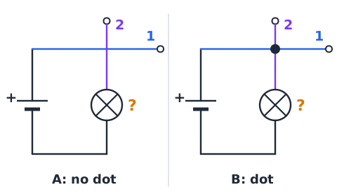
Step 1: No dot means no connection. Step 2: A dot makes the two wires one node.
Answer: Only in version B.
Example: a lamp versus a meter circle
Problem: A circuit contains two circles. One holds an X and the other holds a V. Which one converts energy to light, and how is the other connected?
Step 1: A circle with an X is a lamp, a load. Step 2: A circle with a V is a voltmeter, which sits in parallel across the part it measures.
Answer: The X circle is the lamp; the V circle is a meter connected across a component.
Example: a resistor powers an LED indicator
Problem: A 5 V supply feeds a red LED in series with a 150 Ω resistor. The LED is modeled as dropping 2 V. Find the current.
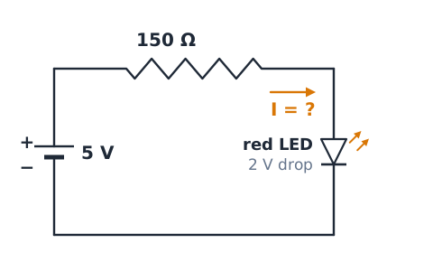
Step 1: The resistor takes the leftover voltage: 5 V minus 2 V is 3 V.
Answer: 20 mA, a typical indicator current set by the resistor.
Example: coil or transformer?
Problem: Drawing A shows one set of four loops labeled L3 100 µH. Drawing B shows two sets of loops facing each other with two straight lines between them, labeled T2. Identify each.
Step 1: A single coil labeled L is an inductor. Step 2: Two coils sharing a core, labeled T, form a transformer. Step 3: The parallel lines show an iron core.
Answer: A is an inductor; B is an iron-core transformer.
Guided drill: label a source and a load
Prompt: A circuit has a 9 V battery, a buzzer, and a resistor. Which is the source? Answer: The battery, since it supplies energy.
Prompt: Which parts are loads? Answer: The buzzer and the resistor, which convert energy to sound and heat.
Prompt: A circle marked G is turned by a bicycle wheel and lights a lamp. Is it a source or a load? Answer: A source; it is a generator.
Guided drill: compare switch positions
Prompt: The switch lever touches its contact. Is current possible? Answer: Yes, it is closed.
Prompt: A pushbutton drawn with its contacts apart is NO or NC? Answer: Normally open.
Prompt: An SPDT switch has how many terminals? Answer: Three, a common contact and two throws.
Guided drill: decode printed values
Prompt: 3.9 kΩ in ohms? Answer: 3,900 Ω.
Prompt: 470 nF in microfarads? Answer: 0.47 µF.
Prompt: 150 mA in amperes? Answer: 0.15 A.
Prompt: 1 MΩ in ohms? Answer: 1,000,000 Ω.
Guided drill: place the measuring symbols
Prompt: To read current through a motor, where does the A circle go? Answer: In series, in the motor's own path.
Prompt: To read voltage across a heater, where does the V circle go? Answer: In parallel, one lead on each heater terminal.
Prompt: Which meter should never be placed directly across a battery? Answer: The ammeter, since its near-zero resistance acts as a short.
Guided drill: use cathode and light arrows
Prompt: A diode's bar is on the right. Which side is the cathode? Answer: The right side.
Prompt: The left side is connected to plus, the right side through a resistor to minus. Forward or reverse? Answer: Forward biased.
Prompt: Arrows point into a diode symbol. What is it? Answer: A photodiode or light detector.
Guided drill: find a crossing error
Prompt: A student says a lamp is shorted because two wires cross on top of it with no dot. The legend says only dots mark joins. Is it shorted? Answer: No; the crossing is not a connection.
Prompt: A dot is added at that crossing, joining the lamp's two terminals. Now? Answer: Yes, the lamp is bypassed and will not light.
ASVAB EI reasoning strategy
Approach every electronics symbol question in a fixed order. First, read the stem for conventions or the word "ideal," and accept them. Second, identify the symbol from its shape and confirm it with any letter, value, or unit. Units are powerful clues: ohms mean resistance, farads mean capacitance, henries mean inductance, amperes on an F label mean a fuse.
Third, check direction for diodes, LEDs, transistors, and cells. Fourth, trace the complete loop and note any open switch or blown fuse. Fifth, if math is involved, convert prefixes before calculating and check that the answer has sensible units.
When stuck, eliminate choices that confuse sources with loads or meters with components, and choices that ignore a stated legend.
Common misconceptions and diagram traps
Mistake: "Open switch means current flows." Why it is wrong: open means the contacts are apart. Fix: closed completes the circuit.
Mistake: every crossing is a junction. Fix: under the usual convention, only dots join wires.
Mistake: the short cell plate is positive. Fix: the long plate is positive.
Mistake: the diode bar is the anode. Fix: the bar is the cathode, and the triangle points that way.
Mistake: a voltmeter goes in series and an ammeter in parallel. Fix: voltmeter across, ammeter in line.
Mistake: reading 4.7 kΩ as 47 Ω. Fix: k means times 1,000, so 4,700 Ω.
Rapid recognition and final recall
Rapid recall: a zigzag or a rectangle is a resistor; an arrow through it makes it variable, and an arrow pointing at it is a potentiometer wiper. Unequal plates are a cell, with the long plate positive. Equal plates are a capacitor, measured in farads. Loops are an inductor, measured in henries; two coils with a core are a transformer.
A triangle and bar is a diode, with the bar as the cathode; outward arrows make an LED, inward arrows a photodiode. A circle with X is a lamp; V, A, and Ω circles are meters; M is a motor. A fuse sacrifices itself, while a breaker resets. Dots join wires; plain crossings do not. Voltmeters go across, ammeters go in series, and every working circuit needs a complete loop.
 English ▾