 ASVAB Camp
Lesson objective and official ASVAB AI relevance
In this lesson you will trace how power travels from the engine to the drive wheels, explain what transmissions, clutches, torque converters, transfer cases and differentials do, and solve gear-ratio problems involving speed, torque and efficiency.
Auto Information questions, scored together with Shop Information as Auto and Shop (AS), help determine qualification for many mechanical and maintenance jobs. They often ask you to name a drivetrain part or its function, so concepts come first and arithmetic second. Every calculation here uses the stated ideal or given-efficiency assumptions.
Trace the complete power path
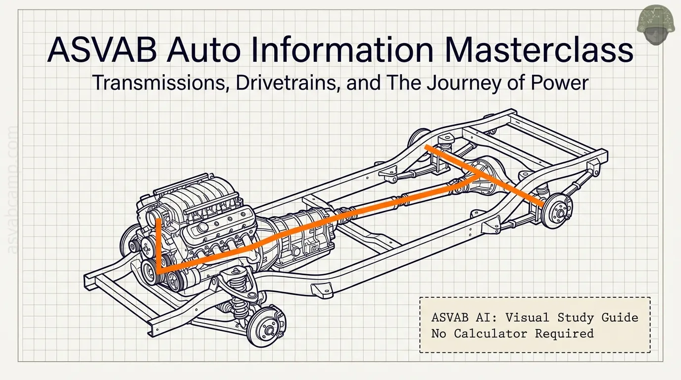
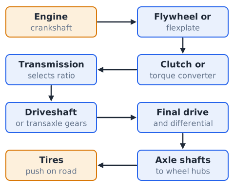
A conventional vehicle's power path runs in a fixed order. The engine produces twisting force at its crankshaft. The flywheel or flexplate passes that rotation to a clutch or torque converter. The transmission selects a gear ratio. A driveshaft, or the gearing inside a transaxle, carries power onward. The final drive and differential reduce speed again and split torque between the left and right axles. Axle shafts turn the wheel hubs, and the tires push against the road.
When a question names a part, place it in this chain and ask what it receives and what it delivers.
Why vehicles need multiple ratios
An engine makes useful torque only within a limited speed band, perhaps about 1,000 to 6,000 rpm in a typical gasoline car, while the wheels must turn anywhere from zero to well over 1,000 rpm. Starting a loaded vehicle uphill needs large wheel torque at low wheel speed. Highway cruising needs moderate torque at higher wheel speed, ideally with the engine turning slowly for economy.
No single fixed ratio serves both jobs. Several gear ratios let the engine stay in its useful range while road speed changes widely.
Define torque versus rotational speed
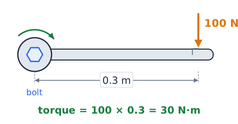
Torque is a twisting effort, the rotational version of force. It equals force times the length of the lever arm and is measured in newton-meters (N·m) or pound-feet. A wrench pushed with 100 N at 0.3 m from a bolt applies 30 N·m.
Rotational speed describes how fast a shaft spins, usually in revolutions per minute (rpm). A shaft can carry large torque at low speed, as in first gear, or smaller torque at high speed. Gears trade one for the other.
Power and realistic transmission losses
Power combines torque and rotational speed. In SI units,
where P is power in watts, T is torque in newton-meters and is angular speed in radians per second. Gears cannot create power. Ideally, a gear set that multiplies torque divides speed by the same factor, so power stays the same. Real gears, bearings and fluid turn some power into heat, which is described by efficiency:
A gearbox taking in 50 kW and delivering 47 kW is 94 percent efficient.
The gear-ratio convention used here
This lesson writes a gear ratio as input speed compared with output speed:
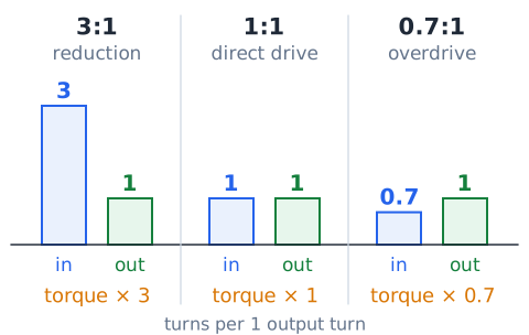
where n is rotational speed in rpm. A 3:1 ratio means the input shaft turns three times for each turn of the output, a speed reduction. A 1:1 ratio is direct drive. A ratio below 1, such as 0.7:1, is overdrive: the output turns faster than the input. Ideal output torque equals input torque times the ratio.
Driving versus driven gear tooth counts
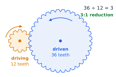
For two meshing gears, the one connected to the power source is the driving gear, and the one it turns is the driven gear. Teeth pass the mesh point one for one, so the speed ratio equals the tooth ratio:
A 12-tooth driving gear turning a 36-tooth driven gear gives 36/12, a 3:1 reduction. The larger driven gear turns more slowly and with more torque.
Reverse rotation and the idler gear
Two external gears in mesh turn in opposite directions. Placing a third gear, called an idler, between them makes the output turn the same way as the input. A manual transmission uses a reverse idler to flip the output direction so the vehicle can back up.
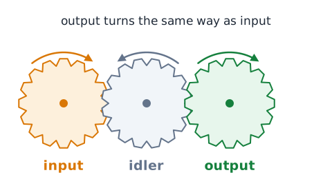
An idler between two gears does not change the overall ratio between them, because it is driven by one gear and drives the next, so its tooth count cancels out. Its job is to change direction or bridge a gap. Reverse gear also usually has a fairly large reduction.
Neutral and the interrupted torque path
In neutral, the transmission does not complete a mechanical path from input shaft to output shaft. The engine can run and some internal parts may spin, but no torque reaches the wheels.
In a manual gearbox, gears may still be in mesh, but none is locked to its shaft. In an automatic, the clutches and bands that select gears are released. Because neutral breaks the torque path, it is used for starting or idling, while a parked vehicle should rely on park and the parking brake.
The clutch in a manual drivetrain
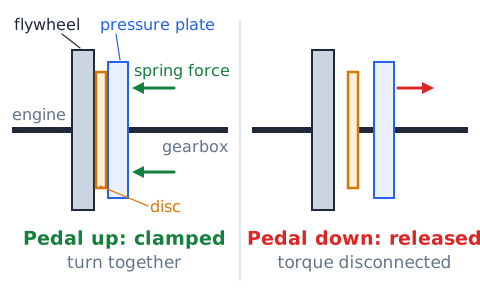
In a manual drivetrain, the clutch sits between the engine's flywheel and the transmission input shaft. With the pedal up, spring force clamps the friction disc between the flywheel and the pressure plate, so the engine and gearbox input turn together.
Pressing the pedal releases that clamping force and disconnects engine torque, so gears can be changed or the vehicle can stop without stalling. Letting the pedal up gradually allows brief slip while the disc brings the gearbox input up to engine speed, giving a smooth start.
Flywheel, pressure plate and friction disc
The flywheel is a heavy disc bolted to the crankshaft. It smooths engine pulses, carries the ring gear the starter engages and provides one friction surface for the clutch. The friction disc, splined to the transmission input shaft, has friction facings on both sides.
The pressure plate assembly, bolted to the flywheel, uses a diaphragm spring to squeeze the disc. A release, or throwout, bearing pushes on that spring when the pedal is pressed. Worn facings often cause slipping, where engine speed rises without matching acceleration.
Manual gearbox gear selection
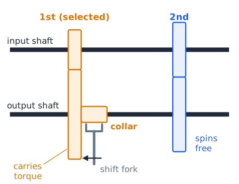
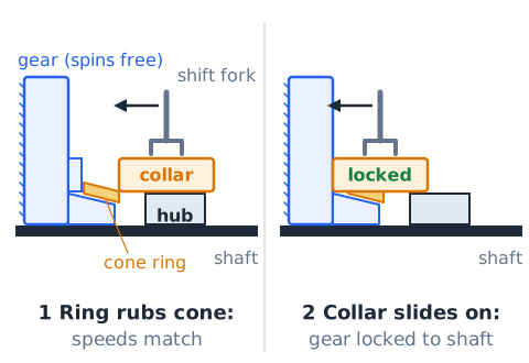
A typical manual gearbox keeps its gear pairs in constant mesh. Gears on the output shaft spin freely on bearings until a sliding collar locks one of them to the shaft. Moving the shift lever moves a shift fork, which slides that collar.
Only the selected pair then carries torque, so its tooth ratio sets the gearbox ratio. Lower gears pair a small driving gear with a large driven gear for strong reduction, while higher gears use pairs that are closer in size.
What a synchronizer does
Before a collar can lock a gear to its shaft, the two parts must turn at the same speed, or their teeth will clash and grind. A synchronizer handles this.
As the shift begins, a cone-shaped ring, often brass, presses against a matching cone on the gear. Friction speeds the gear up or slows it down until it matches the shaft, and only then can the collar slide fully into engagement. Worn synchronizers commonly show up as grinding when shifting into one particular gear.
Gear-ratio choices and vehicle launch
Starting from rest takes the most wheel torque, because the vehicle must overcome inertia, rolling resistance and sometimes a grade. First gear supplies the largest reduction, often around 3:1 to 4:1 in the transmission, so it multiplies engine torque the most.
The trade-off is low road speed for each engine rpm, so the driver or controller shifts up as the vehicle gains speed. A truck towing a heavy trailer may need an even lower ratio, while a light car on level ground can start comfortably in a gear that is not as low.
Direct drive and overdrive
When the input and output shafts turn at the same speed, the ratio is 1:1, called direct drive. In many rear-wheel-drive gearboxes, one gear position locks input to output directly without passing through a gear pair, which is very efficient.
An overdrive ratio is less than 1:1, for example 0.7:1, so the output spins faster than the input. Overdrive lets the engine turn more slowly at highway speed, reducing noise, wear and fuel use, but it provides less torque for climbing or passing.
Torque converters in many automatics
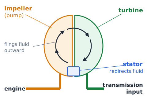
Many automatic transmissions connect to the engine through a torque converter rather than a friction clutch. It is a fluid coupling with three main elements. The impeller, or pump, turns with the engine and flings transmission fluid outward. That fluid strikes the turbine, which is connected to the transmission input, and makes it turn.
A stator between them redirects the returning fluid, which multiplies torque when the turbine is turning much slower than the impeller. Because the fluid allows slip, the engine can idle while the vehicle sits stopped in gear.
Automatic shifting and planetary gears
Most conventional automatic transmissions use planetary gearsets. Each set has a central sun gear, several planet gears mounted on a carrier, and an outer ring gear.
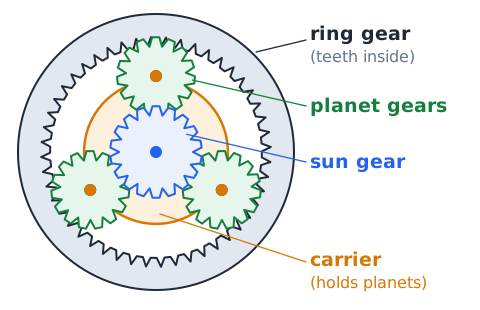
Holding one member still, driving another and taking output from the third produces a reduction, direct drive, overdrive or reverse, depending on which members are chosen. Hydraulically applied clutches and bands make those selections. A control unit, usually electronic today, decides when to shift based on vehicle speed, throttle position and load.
Hydraulic pressure and transmission fluid
Automatic transmission fluid does several jobs at once. It transmits power inside the torque converter, carries hydraulic pressure from the pump to apply clutches and bands, lubricates gears and bearings, and carries heat away to a cooler.
Because shifting depends on pressure, low or worn-out fluid can cause slipping, delayed engagement or harsh shifts. Fluid that is dark or smells burnt may indicate overheating. Manufacturers specify a particular fluid, and the wrong type can change how the internal clutches grip.
Continuously variable transmission basics
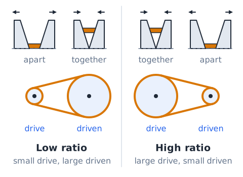
A continuously variable transmission, or CVT, does not have a fixed set of gear steps. A common design runs a steel belt or chain between two pulleys whose halves move closer together or farther apart.
That changes the effective diameter where the belt rides on each pulley, so the ratio can change smoothly across a wide range. The engine can stay near its most efficient speed while the vehicle accelerates, and there are no distinct shift points.
Dual-clutch and automated manuals
A dual-clutch transmission works like two manual gearboxes sharing one case. One clutch serves the odd-numbered gears and the other serves the even-numbered gears. While one gear is driving, the computer preselects the next gear on the other shaft, and a shift happens by releasing one clutch as the other engages, which is very quick.
An automated manual uses a single clutch with actuators that operate it and shift a manual-style gearbox automatically. Neither design needs a torque converter.
What a transaxle combines
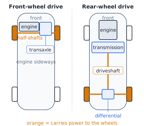
A transaxle combines the transmission, final drive and differential in one housing. It is the usual layout in front-wheel-drive cars with a sideways-mounted engine, and it also appears in some mid-engine and rear-engine vehicles.
Because the final drive is built in, the transaxle's output goes directly to two half-shafts instead of a long driveshaft. Combining these parts saves space and weight and leaves more room for passengers.
Front-wheel-drive power flow
In a typical front-wheel-drive car, the engine sits sideways across the engine bay. Power goes from the crankshaft through the clutch or torque converter into the transaxle. Inside, the gearbox selects a ratio and passes power to the final drive gear and differential.
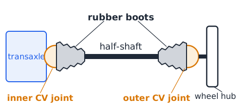
From the differential, two half-shafts fitted with constant-velocity joints carry power to the front wheels. Those wheels also steer, so the joints must transmit torque while the wheels turn left and right and move up and down.
Rear-wheel-drive power flow
In a conventional rear-wheel-drive vehicle, the engine is usually mounted lengthwise at the front. Power flows through the clutch or torque converter into a separate transmission behind the engine.
A propeller shaft, or driveshaft, runs from the transmission back to the rear axle. There, a ring-and-pinion gear set provides the final drive and turns the differential, which drives the left and right rear axle shafts.
Propeller shaft and shaft joints
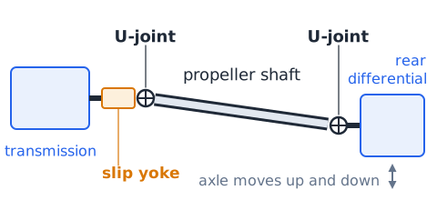
The propeller shaft is a tube that carries torque from the transmission to the rear differential in many rear-wheel-drive and four-wheel-drive vehicles. Because the rear axle moves up and down with the suspension, the shaft's angle keeps changing.
Universal joints at the ends allow that angle change, and a slip yoke lets the shaft's length change slightly. Long shafts may be built in two pieces with a center support bearing. A worn U-joint can cause clunking or vibration.
Constant-velocity joints on drive axles
A simple universal joint operating at an angle makes its output speed speed up and slow down slightly during each turn. That is acceptable at small angles but not at the large angles of steered front wheels.
A constant-velocity, or CV, joint keeps output speed steady through large angles by using balls or rollers in grooved races. Front-wheel-drive half-shafts usually have an inner and an outer CV joint, each covered by a rubber boot that holds grease in and keeps dirt and water out.
Why a final drive is needed
Even in top gear, the transmission output usually turns much faster than the wheels should. The final drive adds a fixed reduction, often about 3:1 to 4:1, so wheel speed suits road speed.
In a rear-wheel-drive axle, the final drive is the small pinion gear turning the large ring gear. Because it sits after the transmission, it multiplies torque in every gear, and the overall ratio is the transmission ratio times the final-drive ratio.
Open differential purpose
In a turn, the outside wheel travels a longer arc than the inside wheel, so it must rotate faster. If both wheels were fixed to one solid shaft, one tire would have to scrub or hop across the pavement.
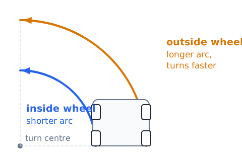
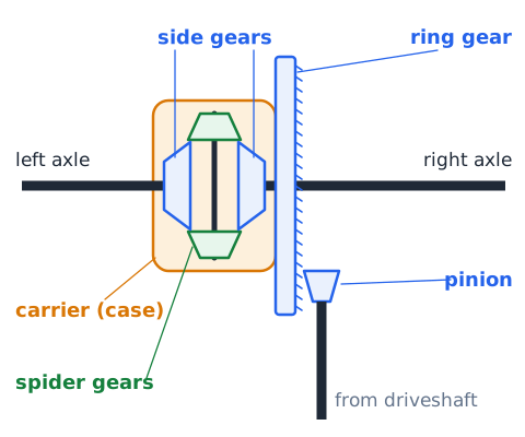
The differential solves this. Its carrier, or case, is turned by the ring gear, and small spider gears inside it let the two side gears and their axles turn at different speeds while both still receive drive. When the vehicle goes straight, the spider gears do not spin on their shaft.
Differential speed relationship
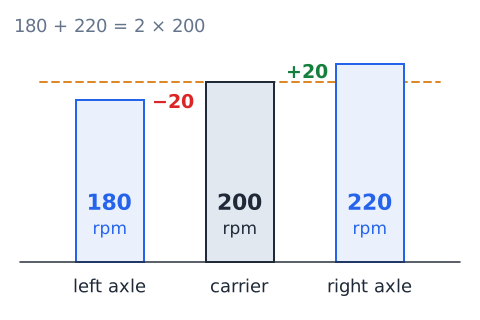
For an open differential with equal side gears, carrier speed is the average of the two axle speeds:
Here is carrier rpm and and are the left and right axle rpm. Equivalently,
If the carrier turns at 200 rpm and the left axle turns at 180 rpm, the right axle turns at
One wheel speeds up by exactly as much as the other slows down.
Limited-slip and locking differentials
An open differential sends equal torque to both axles, but that torque is limited by the wheel with the least grip. If one wheel sits on ice, it spins easily and the other wheel receives little useful torque.
A limited-slip differential uses clutch packs, special gearing or viscous fluid to resist large speed differences, so more torque can reach the wheel that has traction. A locking differential can tie both axles together so they turn at the same speed. That helps off road at low speed but causes tire scrub and heavy steering on dry pavement, so lockers are engaged only when needed.
Front-, rear- and all-wheel drive
Front-wheel drive (FWD) powers the front wheels, which also steer; it is compact and puts engine weight over the driven wheels. Rear-wheel drive (RWD) powers the rear wheels, separating steering from driving, and it often suits heavy loads and towing.
All-wheel drive (AWD) can power all four wheels on pavement, usually automatically, using a center differential or clutch pack to handle front-to-rear speed differences. Four-wheel drive (4WD) often lets the driver engage the front axle and select a low range.
Transfer case in many 4WD layouts
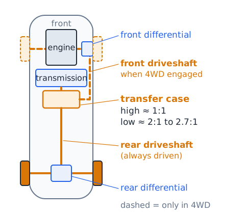
In many four-wheel-drive trucks and SUVs, a transfer case mounts behind the transmission. It always sends power to the rear driveshaft and, when four-wheel drive is engaged, also to a front driveshaft leading to the front differential.
Many transfer cases offer a high range of about 1:1 and a low range, often around 2:1 to 2.7:1, which multiplies torque for steep climbs and slow crawling. In part-time systems the front and rear shafts are locked together, so 4WD is meant for loose or slippery surfaces.
AWD does not mean every wheel equal rpm
All-wheel drive means every wheel can receive drive torque, not that every wheel turns at the same speed. In a turn, each of the four wheels follows a different path and so has a different rpm, and the front and rear axles need slightly different average speeds.
AWD systems include a center differential, a viscous coupling or electronically controlled clutches to allow these differences. Without that allowance, the driveline winds up and the tires scrub, a condition called driveline binding.
Wheel torque and available traction
Torque at the wheel can push the vehicle only as hard as the tire's grip allows. Traction depends on the friction between tire and surface and on how much weight presses that tire down.
On dry pavement there is plenty of grip, but on ice, mud or loose gravel a low gear can deliver more torque than the tire can use, and the wheel spins. In that situation a higher gear, gentler throttle or a limited-slip or locking differential may move the vehicle better than more torque.
Gear changes and engine braking
When the driver lifts off the accelerator with the vehicle in gear, the wheels drive the engine back through the drivetrain, and the engine's internal friction and pumping resistance slow the vehicle. This is engine braking.
A lower gear makes the engine turn faster at the same road speed, so it gives stronger braking. On long downhill grades, choosing a lower gear helps hold a steady speed and keeps the service brakes from overheating and fading. A downshift must still keep the engine below its maximum safe rpm.
Gear selection and fuel efficiency
An engine generally uses fuel more efficiently at moderate speed and load than when it spins fast under light load. Shifting to the highest gear that still delivers enough power, including overdrive, lets the engine turn slowly at cruise and cuts friction and pumping losses.
Lugging the engine at very low rpm in too high a gear, however, causes vibration and sluggish response. Automatics with many ratios, and CVTs, aim to keep the engine near its efficient operating point.
Typical warning signs without overdiagnosis
Some symptoms suggest drivetrain trouble: a clutch that slips or chatters, grinding during shifts, delayed engagement in an automatic, a clunk when moving between drive and reverse, vibration that changes with road speed, clicking from a front axle while turning, whining that rises with speed, or fluid leaks.
Each symptom has several possible causes. Clicking in tight turns, for example, often points to a worn outer CV joint but does not prove it. Diagnosis belongs to a qualified technician.
Safe vehicle maintenance boundaries
Drivetrain parts are heavy, rotate with great force and may be hot. Never get under a vehicle held up only by a jack; properly rated jack stands on firm, level ground and wheel chocks are the general rule. A vehicle in neutral, or with its drive wheels raised, can roll or spin a wheel unexpectedly.
Rotating shafts can catch clothing, and hot fluid can burn. Simple inspections such as looking for leaks are reasonable for many owners, while internal repairs belong to trained technicians with proper equipment.
Axle shafts, wheel hubs and bearings
Axle shafts carry torque from the differential side gears to the wheels. On a solid rear axle they run inside the axle housing; on independent suspension they are half-shafts with joints at each end.
The wheel hub is the part the wheel bolts to. Wheel bearings let the hub turn smoothly while supporting the vehicle's weight and cornering forces. A failing wheel bearing often makes a growl or hum that grows louder with speed and may change while turning.
Four-wheel-drive low range versus low transmission gear
Selecting first gear and selecting four-wheel-drive low range are different actions. First gear is a transmission ratio. Low range is a separate reduction inside the transfer case that multiplies whatever ratio the transmission is using.
With a 4:1 first gear and a 2.5:1 low range, the combined reduction before the final drive is 10:1. Low range is meant for slow, controlled driving on steep or rough ground, not for normal road speeds.
Numerical ratios: reduction and overdrive
Read a ratio by its number. Ratios greater than 1, such as 3.5:1, are reductions: output turns slower with more torque. A ratio of exactly 1 is direct drive. Ratios less than 1, such as 0.75:1, are overdrives: output turns faster with less torque.
A numerically higher ratio means a "lower" gear with more reduction. That is why first gear is called low gear even though its ratio number is the largest.
Torque multiplication with specified efficiency
Ideal output torque is input torque times the ratio. Real gearboxes lose some power, so multiply by efficiency too:
Write efficiency as a decimal. For example, 150 N·m entering a 2.5:1 reduction at 90 percent efficiency gives
N·m. Output speed still follows the ratio alone.
Speed and tire circumference
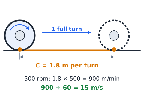
Each wheel revolution moves the vehicle forward one rolling circumference, assuming no slip:
where v is vehicle speed, C is circumference and n is wheel speed. Watch the units: meters times revolutions per minute gives meters per minute, so divide by 60 for meters per second. A wheel with a 1.8 m circumference turning at 500 rpm covers 900 m each minute, which is 15 m/s.
Mechanical work and unit discipline
Work is force times the distance moved in the direction of the force:
With force in newtons and distance in meters, work comes out in joules. Torque is also written in N·m, but torque is not energy. Power is work divided by time, in watts. Pushing a cart with 400 N through 25 m does 10,000 J of work; doing it in 20 s takes 500 W. Convert kilometers, minutes and kilonewtons before calculating.
Diagnosing torque path versus road load
When a vehicle struggles, separate two questions. Is the drivetrain failing to deliver torque because something in the path is slipping or disconnected, such as a worn clutch, low fluid or a broken axle? Or is the road load simply high, from a steep grade, heavy trailer, soft ground or strong headwind?
A slipping clutch shows engine speed rising without matching acceleration. A heavy load shows engine and road speed staying in step while acceleration is slow. The evidence points to different causes.
Differential and wheel-speed corner case
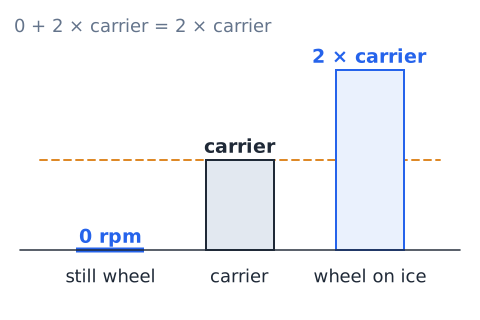
With an open differential, if one drive wheel is lifted off the ground or sits on ice while the carrier turns, that wheel can spin at twice the carrier speed while the other wheel stays still.
This follows directly from the average rule: if one axle is at 0 rpm, the other must be at two times the carrier speed. It explains why a vehicle with one wheel on ice may not move at all. A limited-slip or locking differential changes this behavior.
Highway speed and gear ratio interpretation
At a fixed road speed, the wheels turn at a fixed rpm, and engine rpm equals wheel rpm times the overall ratio. A numerically higher overall ratio therefore means a higher engine speed at the same road speed: more torque available, but more engine revolutions per mile.
A numerically lower ratio, such as an overdrive with a modest final drive, lowers cruising rpm. If the wheels turn at 800 rpm and the overall ratio is 2.4:1, the engine turns at 1,920 rpm.
Hybrid and electric driveline perspective
Electric motors produce strong torque from zero rpm and work across a very wide speed range, so many battery-electric vehicles use a single fixed reduction, often around 8:1 to 10:1, instead of a multi-speed transmission. They still need a differential and drive shafts to the wheels.
Some hybrids use a planetary gearset as a power-split device that blends engine and motor output and behaves like a continuously variable transmission. The same rules for ratio, torque and speed still apply.
Torque converter versus clutch quick contrast
A friction clutch and a torque converter both sit between engine and transmission, but they work differently. A clutch is a mechanical friction device that is engaged, slipping or released, operated by the driver's pedal in a manual car.
A torque converter is a fluid coupling that always allows some slip, multiplies torque at low turbine speed and needs no pedal. Many converters add a lock-up clutch that joins engine and transmission mechanically at cruise, cutting slip losses.
The final-drive relationship is multiplicative
Ratios in series multiply. The overall reduction from engine to wheels equals the transmission ratio times the final-drive ratio, and times a transfer-case ratio if one is in the path:
A 2.8:1 gear with a 3.5:1 final drive gives 9.8:1. Adding them to get 6.3:1 is a common wrong answer.
Test strategy: label input and output
Before calculating, label which shaft is the input and which is the output, and write the ratio as input to output. If the question gives tooth counts, decide which gear is driving.
Then ask whether the ratio is a reduction or an overdrive. A reduction must give lower output speed and higher output torque; an overdrive must do the opposite. If your result moves the wrong way, you probably multiplied when you should have divided. This quick check catches most ratio errors on the exam.
Worked 01 — gearbox speed reduction
Problem: The gearbox input turns at 3,000 rpm in a gear with a 2.5:1 ratio. Find the output speed.
Check: a reduction should slow the output, and 1,200 rpm is less than 3,000 rpm. Answer: 1,200 rpm.
Worked 02 — simple spur gear tooth count
Problem: A 14-tooth driving gear meshes with a 42-tooth driven gear. Find the ratio and the output speed for a 1,500 rpm input.
Output speed is
and the driven gear turns the opposite way. Answer: 3:1 and 500 rpm.
Worked 03 — ideal output torque
Problem: A 3.5:1 reduction receives 80 N·m. Find the ideal output torque.
Check: a reduction should raise torque, and it did. Answer: 280 N·m, while output speed falls by the same factor of 3.5.
Worked 04 — efficiency adjusted torque
Problem: A 2:1 gearbox receives 200 N·m and is 85 percent efficient. Find the output torque.
The ideal value would be 400 N·m, so losses remove 60 N·m. Answer: 340 N·m.
Worked 05 — compounded gearbox and axle
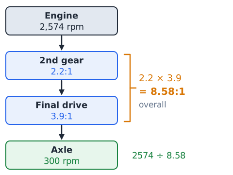
Problem: Second gear is 2.2:1 and the final drive is 3.9:1. The engine turns at 2,574 rpm. Find the overall ratio and axle speed.
Answer: 8.58:1 overall and 300 rpm at the axle.
Worked 06 — an overdrive comparison
Problem: With 2,100 rpm at the input, compare output speed in a 1:1 gear and in a 0.7:1 overdrive.
Direct drive:
Overdrive:
Answer: overdrive raises output speed to 3,000 rpm, while ideal output torque falls to 0.7 times the input torque.
Worked 07 — rolling circumference road speed
Problem: A tire with a 2.1 m rolling circumference turns at 600 rpm. Find the vehicle speed.
Answer: 21 m/s, about 76 km/h.
Worked 08 — open differential average speed
Problem: In a turn, the outside rear wheel turns at 330 rpm and the inside wheel at 270 rpm. The tires are equal and the differential is open. Find the carrier speed.
Answer: 300 rpm. The outside wheel runs 30 rpm faster than the carrier and the inside wheel 30 rpm slower.
Worked 09 — find missing wheel speed
Problem: A differential carrier turns at 250 rpm and the right axle at 290 rpm. Find the left axle speed.
Answer: 210 rpm, which is 40 rpm below the carrier, mirroring the right side's 40 rpm above it.
Worked 10 — identify a power path
Scenario: A pickup has a lengthwise engine, an automatic transmission, a transfer case with a range selector, a driveshaft to each axle and a differential in both axles.
Reasoning: The lengthwise engine and rear driveshaft indicate a rear-drive base. The transfer case and front driveshaft add a path to the front differential.
Answer: engine, torque converter, transmission, transfer case, then front and rear driveshafts, differentials, axles and wheels. This is a 4WD layout.
Worked 11 — efficiency by power
Problem: A transfer case receives 60 kW and delivers 57 kW. Find its efficiency and the power lost.
Answer: 95 percent efficient, with 3 kW turned into heat in the gears, bearings and lubricant.
Worked 12 — transfer-case low range
Problem: A truck uses a 3.5:1 first gear, a 2.7:1 transfer-case low range and a 4.1:1 final drive. Find the overall ratio.
Answer: about 38.7:1, so the wheels turn once for roughly every 38.7 engine revolutions.
Worked 13 — converter identification
Scenario: A vehicle has no clutch pedal. Stopped in drive with the brakes held, the engine idles without stalling. At steady highway speed, engine rpm drops slightly as something engages.
Reasoning: Idling while stopped in gear requires slip between engine and transmission, which a fluid coupling provides. The small rpm drop at cruise matches a lock-up clutch removing that slip.
Answer: a torque converter with a lock-up clutch.
Worked 14 — slope and gear choice
Problem: Climbing a grade requires 1,800 N·m at the axle. The engine supplies 150 N·m and the final drive is 4:1. Ignoring losses, what is the minimum transmission ratio?
Answer: at least 3:1. A 3.6:1 first gear would work, but a 1.4:1 third gear would not.
Guided drill 01 — trace FWD and RWD
Prompt: Put these in order for front-wheel drive: half-shafts, engine, transaxle, clutch. Answer: engine, clutch, transaxle, half-shafts.
Prompt: Put these in order for rear-wheel drive: differential, transmission, driveshaft, engine, axle shafts. Answer: engine, transmission, driveshaft, differential, axle shafts.
Prompt: Which layout sends power through CV-jointed shafts to wheels that also steer? Answer: FWD.
Guided drill 02 — compute three speed ratios
The input is 3,600 rpm for each prompt.
Prompt: 4:1. Answer:
a strong reduction such as a low gear.
Prompt: 1.5:1. Answer:
a milder reduction.
Prompt: 0.8:1. Answer:
an overdrive, so the output turns faster than the input.
Guided drill 03 — two linked reductions
Prompt: A 2:1 gearbox and a 3.5:1 final drive. Answer: 7:1 overall.
Prompt: A 10-tooth gear drives a 30-tooth gear, followed by a 4.2:1 final drive. Answer:
so 12.6:1.
Prompt: The engine turns 2,800 rpm through 7:1 overall. Answer: 400 rpm at the axle.
Guided drill 04 — compare clutch and converter
Prompt: Which one uses a pedal and friction facings? Answer: the clutch.
Prompt: Which transfers power through moving fluid? Answer: the torque converter.
Prompt: Which can multiply torque by itself? Answer: the torque converter, through its stator at low turbine speed.
Prompt: Which lets the engine idle in gear with no pedal input? Answer: the torque converter.
Guided drill 05 — differential wheel speeds
Prompt: Carrier 160 rpm, left wheel 140 rpm. Answer: right wheel 180 rpm.
Prompt: Left wheel 95 rpm, right wheel 125 rpm. Answer: carrier 110 rpm.
Prompt: Carrier 75 rpm, one wheel held still. Answer: the other wheel turns 150 rpm.
Guided drill 06 — safe symptom interpretation
Prompt: Engine rpm climbs on a hill but road speed does not. Answer: possible clutch or transmission slip; have it evaluated.
Prompt: Clicking from the front only in sharp turns. Answer: possibly a worn outer CV joint, not proven.
Prompt: A growl that rises with road speed. Answer: possibly a wheel bearing or another rotating part.
Prompt: A red fluid spot under the car. Answer: possible transmission fluid leak; refer to a qualified technician.
Auto Information exam strategy for drivetrains
Drivetrain questions on Auto Information fall into two groups. Identification items ask what a part does or where it sits. Answer them by placing the part in the power path from engine to tire and eliminating choices from other systems, such as cooling, ignition or brakes.
Calculation items use ratios. Write the ratio as input speed to output speed, divide input speed by the ratio to get output speed, and multiply input torque by the ratio to get output torque. Multiply ratios that follow one another. Apply efficiency only to torque or power, never to speed. Finally, check direction: reductions slow the output and raise torque.
Common transmission and drivetrain traps
Mistake: adding ratios in series. Why it is wrong: each stage scales the speed left by the stage before it. Fix: multiply, so 3:1 followed by 4:1 gives 12:1, not 7:1.
Mistake: believing gears add power. Why it is wrong: ideal gears trade torque for speed and keep power constant, and real gears lose some. Fix: when torque goes up, speed goes down.
Mistake: applying efficiency to speed. Why it is wrong: rigid gear teeth do not slip, so speed follows the ratio exactly. Fix: multiply only torque or power by efficiency.
Mistake: thinking AWD keeps every wheel at equal rpm. Why it is wrong: wheels follow different paths in a turn. Fix: remember the differentials allow different speeds.
Mistake: flipping the tooth ratio. Fix: divide driven teeth by driving teeth.
Drivetrain quick reference
Power flows from the engine through a clutch or torque converter, the transmission, a driveshaft or transaxle, the final drive and differential, and the axles to the wheels. Several ratios keep the engine in its useful speed range.
A clutch connects and disconnects engine torque by friction; a torque converter couples through fluid, can multiply torque, and may use a lock-up clutch to cut slip. Synchronizers match speeds for quiet manual shifts. Planetary gearsets supply automatic ratios, and CVTs vary the ratio smoothly. A transaxle combines gearbox and differential. CV joints drive steered wheels; U-joints serve driveshafts. The differential lets wheels turn at different speeds, with carrier speed equal to their average, and a transfer case splits power front and rear and may add low range.
Ratio is input speed over output speed. Output speed equals input divided by ratio, output torque equals input times ratio times efficiency, and stages multiply.
 English ▾