 ASVAB Camp
What you will understand
In this lesson you will name the main steering and suspension parts and state what each one does. You will read toe, camber and caster by their viewing directions, separate alignment from balancing, and reason about symptoms without jumping to one cause. You will also work steering-ratio, spring-force, spring-energy and turning-radius problems, and learn why spring work belongs to trained technicians.
Two systems that must cooperate
Steering points the front wheels where the driver wants to go. Suspension holds the body up, lets the wheels move over bumps and keeps the tires pressed onto the road. The two share parts, such as the knuckle, ball joints and control arms. If the suspension lets a tire bounce off the pavement, even perfect steering cannot turn the car, because a tire in the air makes no grip.
Follow the driver-to-tire steering path
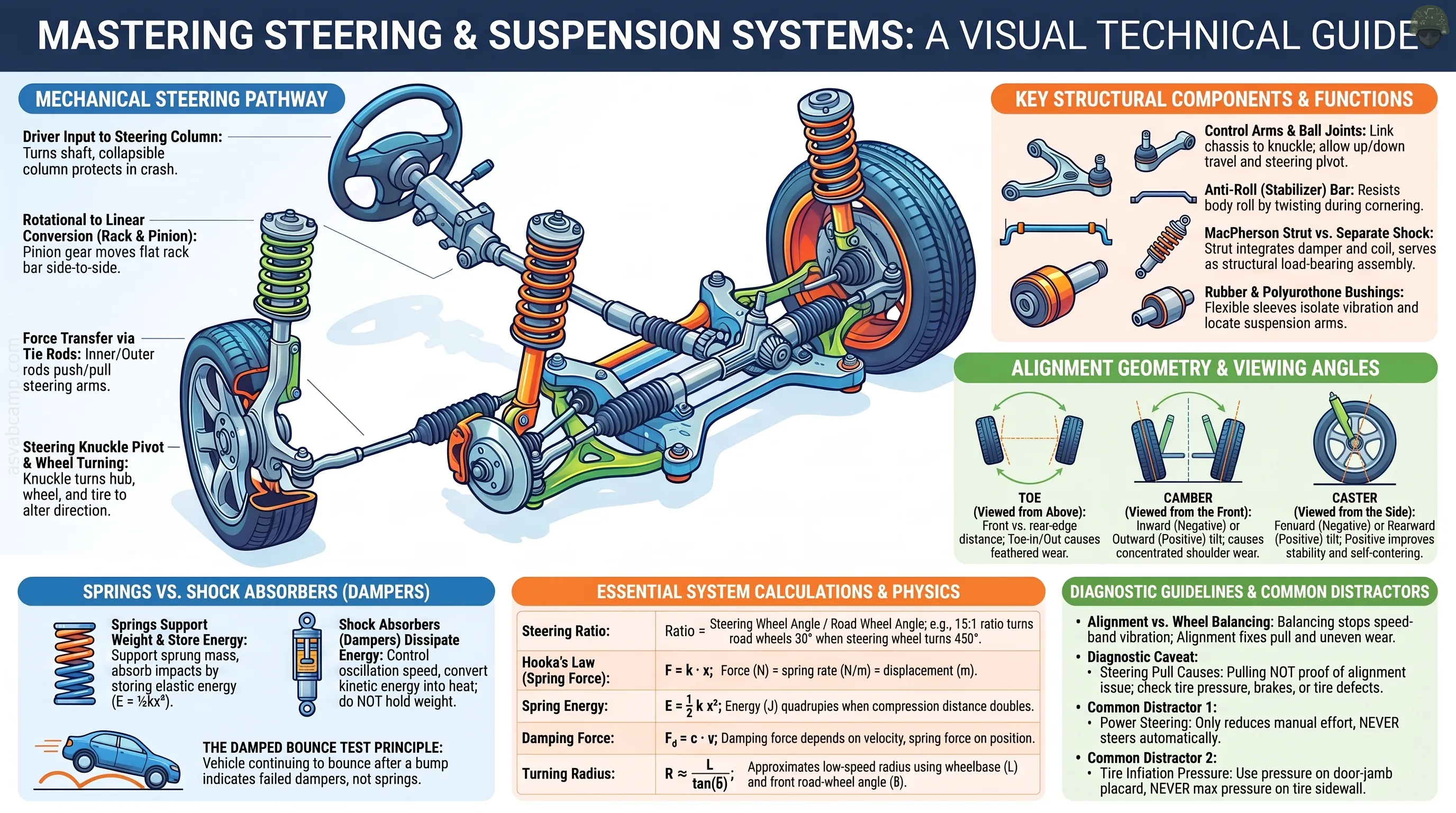
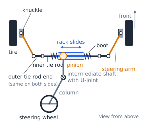
In a typical car the path is: steering wheel, steering column and shaft, intermediate shaft with universal joints, pinion gear, rack, inner tie rods, outer tie rod ends, steering arms on the knuckles, and finally the wheels and tires. Turning the wheel spins the pinion, which slides the rack sideways. The tie rods push or pull each knuckle so the wheels pivot together.
Steering wheel and collapsible column
The steering wheel gives the driver leverage and houses the driver airbag, horn switch and often control buttons. The column carries the steering shaft to the gear and supports the turn-signal and wiper switches. Columns are built to collapse or telescope in a frontal crash, so the wheel is less likely to be driven toward the driver. Many columns also tilt or telescope for fit.
The pinion turns the rack
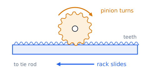
A rack-and-pinion gear converts rotation into straight-line motion. The pinion is a small round gear at the end of the steering shaft. The rack is a long bar with teeth cut along one side. When the pinion turns, its teeth push the rack left or right inside its housing. The rack never spins; it slides side to side and carries the tie rods with it.
Inner versus outer tie rod
Each side of the rack connects to a wheel through a tie rod. The inner tie rod screws onto the rack end and uses a ball joint hidden inside a rubber bellows boot. The outer tie rod end attaches to the steering arm on the knuckle with its own ball stud. Threads between the two let a technician set toe. Both joints must swivel so the linkage keeps working as the wheel moves up, down and sideways.
Steering knuckle, hub and bearing
The steering knuckle is the sturdy part each front wheel hangs on. It connects to the control arms or strut through ball joints and to the tie rod through a steering arm. It also carries the hub and wheel bearing. The bearing lets the hub and wheel spin with very little friction while the knuckle itself only pivots for steering and moves for suspension travel.
Steering axis is not the wheel axle
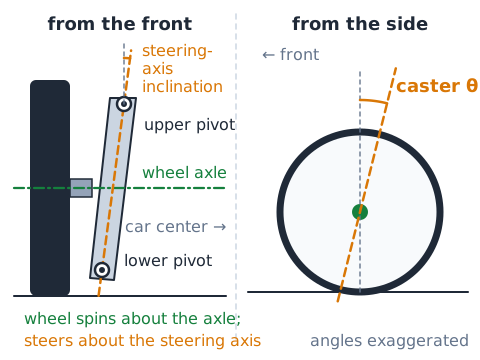
The wheel spins about its axle, a horizontal line through the hub. Steering happens about a different line, the steering axis, which runs through the upper and lower pivot points. That axis is tilted. Its tilt seen from the side is caster, angle in many diagrams. Its inward tilt seen from the front is steering-axis inclination.
Recirculating-ball and steering linkage alternatives
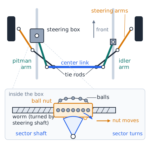
Many trucks and older cars use a recirculating-ball steering box instead of a rack. The steering shaft turns a worm, and steel balls rolling in a closed loop move a nut that rotates a sector shaft. A pitman arm on that shaft swings a linkage of center link, idler arm and tie rods. This design is rugged and suits heavy loads and solid front axles, but it feels less direct than rack and pinion.
Steering ratio and tradeoffs
Steering ratio compares how far the steering wheel turns to how far the road wheels turn.
A 16:1 ratio means 16 degrees at the wheel for about 1 degree at the tires. A lower number, like 12:1, feels quicker but takes more effort. A higher number, like 20:1, needs less effort but more turning. Many racks vary the ratio with steering angle.
Steering-ratio example
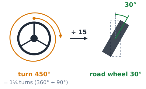
A car has a nominal 15:1 steering ratio. The driver turns the steering wheel 450°. What road-wheel angle does the ideal model predict?
Answer: about 30°. Real values vary a bit with linkage geometry and suspension position, so treat it as a representative figure.
Mechanical steering and power assist
Even without assistance, the steering wheel is mechanically linked to the road wheels through the shaft, gear and tie rods. Power steering adds a helping force so the driver needs less effort, especially when parking or at low speed. Older or very light cars may have no assist at all. If assist fails in a conventional system, the car can still be steered, but it takes much more muscle.
Hydraulic power steering overview
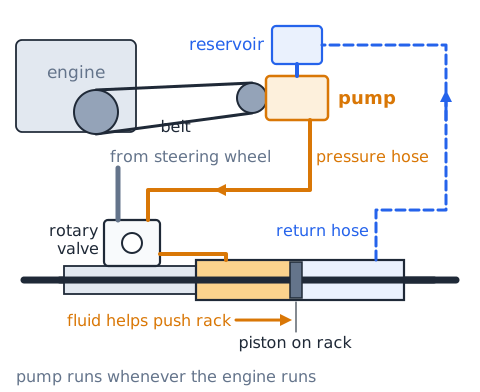
Traditional hydraulic power steering uses an engine-driven pump that pushes fluid through hoses to the steering gear. A rotary valve senses the driver's effort and sends pressurized fluid to one side of a piston on the rack, helping push it. A reservoir holds the fluid. The pump runs whenever the engine runs, so this layout costs some fuel.
Electric power steering overview
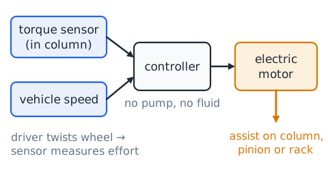
Electric power steering, or EPS, removes the pump and fluid. A torque sensor in the column measures how hard the driver is twisting the wheel. A controller reads that signal along with vehicle speed and commands an electric motor, mounted on the column, the pinion or the rack, to add the right amount of help. It draws power only when assist is needed and enables features like lane-keeping assist.
Speed-dependent steering assist
Drivers want light steering in a parking lot and steadier, heavier steering on the highway. Many systems change assist with speed: more help at a crawl, less at speed. EPS does this in software using the speed signal. Some hydraulic systems use a control valve for the same effect. The goal is easy maneuvering without twitchy highway feel.
Do not confuse assist with automatic steering
Power steering only reduces the force the driver needs; the driver still chooses the direction. The assist system amplifies what the driver does at the wheel. Driver aids such as lane centering can use the EPS motor to apply small corrections, but the driver remains responsible for steering. On a test, a choice saying power steering drives the car by itself, or that it creates grip, is a distractor.
Steering free play and vague response
Free play is the amount the steering wheel can move before the road wheels respond. A small amount is normal. Excess play makes the car wander and demands constant correction. Causes include worn inner or outer tie rod ends, a worn idler arm or pitman arm, loose steering-gear mounts, worn ball joints or a loose wheel bearing. Each joint must be checked; play rarely has only one source.
Hydraulic assist fluid issues
In hydraulic systems, low fluid can let the pump draw in air, causing whining, foamy fluid and jerky or heavy steering. Leaks at hoses, the pump or the rack seals drop the level over time. A slipping or broken drive belt also cuts assist. The fix starts with finding the leak and using the fluid type the maker specifies, since some systems need special fluid.
What the suspension must accomplish
Suspension has several jobs at once. It supports the vehicle's weight, absorbs bumps so passengers ride smoothly, and keeps each tire in firm contact with the road for braking, steering and accelerating. It also controls body motion, limiting roll in turns, dive in braking and squat under acceleration, and it holds the wheels at the right angles. Each part contributes to one or more of these goals.
Springs store and release energy
When a wheel hits a bump, the spring is compressed and stores elastic energy. As the wheel moves back down, the spring releases that energy. For an ideal linear spring,
where E is energy in joules, k is stiffness in N/m and x is compression in meters. Doubling x stores four times the energy.
Coil spring: force proportional to displacement
For an ideal coil spring, force grows in proportion to how far it is compressed. This is Hooke's law.
F is force in newtons, k is the spring rate in N/m, and x is compression in m. A spring with
N/m compressed 0.05 m pushes back with 1,000 N.
Hooke’s law with unit conversion
A spring has a rate of 40,000 N/m. How much extra force compresses it 18 mm?
Convert first: 18 mm = 0.018 m.
Answer: 720 N. Using 18 instead of 0.018 would give a figure 1,000 times too large.
Stiffer spring does not equal better grip everywhere
Stiffer springs reduce body roll and dive, which can sharpen handling on smooth roads. On rough surfaces, however, a very stiff spring lets the tire skip over bumps rather than follow them, so grip can drop. Ride comfort suffers too. Spring rates are a compromise chosen for the vehicle's weight, purpose and expected roads.
What shock absorbers actually do
A shock absorber, more accurately called a damper, does not hold the car up; the springs do that. The damper controls how fast the spring compresses and rebounds. Inside, a piston pushes oil through small valved passages, and that resistance turns motion energy into heat. Without damping, a car would keep bouncing after every bump, and the tires would lose contact with the road.
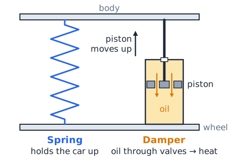
Compression damping and rebound damping
A damper resists movement in both directions. Compression, or bump, damping acts as the wheel moves up toward the body. Rebound damping acts as the spring pushes the wheel back down and the body back up. Dampers usually have more rebound control, which keeps the spring from throwing the body upward. Each direction has its own valve setting.
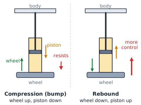
Damped bounce: the conceptual test
Scenario: a vehicle drives over a single speed bump. With good dampers, the body rises, settles past level a small amount and comes to rest in roughly one cycle. With a damper that has lost its oil, the body keeps rising and falling several times after the bump.
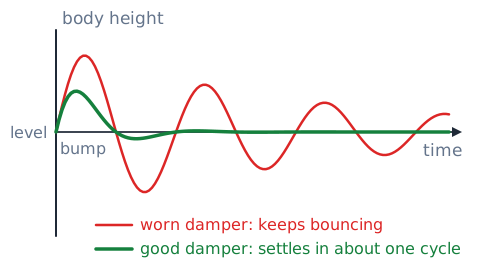
Reasoning: the spring still holds the car at normal height, so the ride height is unchanged. What is missing is the energy-absorbing resistance. Answer: prolonged bouncing points to the damper, not the spring.
Strut versus separate shock absorber
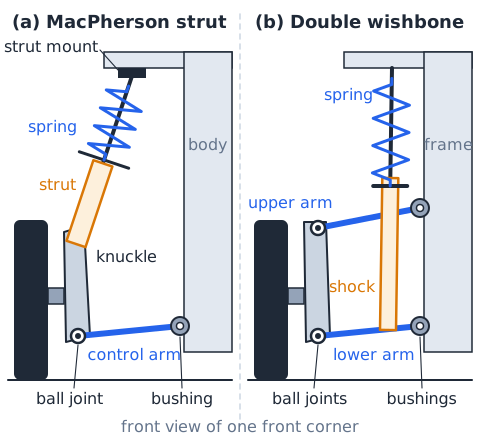
A separate shock absorber only damps. It mounts between the body and a control arm or axle, and the spring sits elsewhere. A MacPherson strut combines a damper with a coil spring seat and also serves as a structural part of the suspension, locating the top of the knuckle and carrying side loads. Replacing a strut can therefore affect alignment, while replacing a separate shock usually does not.
Strut mount and rotation
At the top of a front strut sits the strut mount, a rubber-insulated plate bolted to the body. On steered struts it includes a bearing so the strut and spring can rotate as the wheels turn. A worn mount may cause clunks, creaks, binding or a popping sound when steering, and it can change alignment angles. The mount is part of the steering axis on this design.
Control arms guide wheel motion
Control arms are hinged links that connect the knuckle or axle to the frame or body. They let the wheel move up and down while preventing unwanted motion forward, backward or sideways. Double-wishbone designs use an upper and a lower arm; MacPherson designs use one lower arm plus the strut. Bushings at the body end and a ball joint at the knuckle end let the arm pivot.
Ball joints permit angular movement
A ball joint is a ball-and-socket pivot that connects a control arm to the steering knuckle. It allows the knuckle to swing up and down with suspension travel and to rotate as the wheels steer, all at once. Tie rod ends use a similar design. Worn ball joints develop looseness, causing clunks, wandering and uneven tire wear, and a badly worn one can separate.
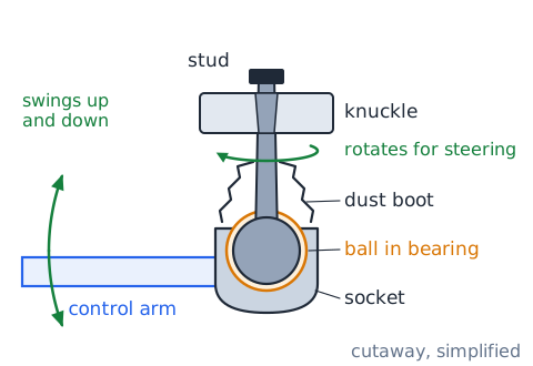
Bushings isolate and locate
Bushings are rubber or polyurethane sleeves pressed into control arms, stabilizer bars and subframe mounts. They let parts pivot while soaking up vibration and noise so road harshness does not reach the cabin. They also hold the arms in position. Cracked or soft bushings allow extra movement, which can cause clunks, wander and alignment changes.
Anti-roll (stabilizer) bar function
An anti-roll bar, also called a stabilizer or sway bar, is a spring-steel bar running across the vehicle that links the left and right suspensions. When both wheels rise together it does little. When one side compresses more than the other, as in a turn, the bar twists and resists that difference, reducing body roll. End links connect the bar to each side.
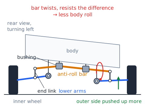
Anti-roll bar tradeoffs
A thicker anti-roll bar cuts body lean, but it also couples the two sides more tightly. A bump under one wheel then pulls on the other side, which can feel harsher and reduce independent wheel motion. Making the front bar stiffer than the rear tends to increase understeer, and stiffening the rear tends to increase oversteer. Engineers balance both ends.
Leaf springs in vehicle suspensions
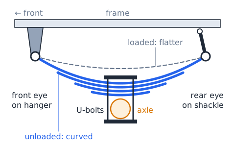
A leaf spring is a stack of curved steel strips clamped together. It bends under load and flattens as weight is added. Leaf springs are common on pickup trucks, vans and trailers because they carry heavy loads and also help locate the axle, so fewer extra links are needed. Their drawbacks are weight and friction between leaves.
Torsion-bar springs
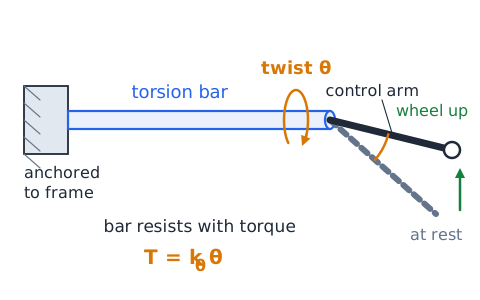
A torsion bar is a straight steel rod anchored at one end and attached to a control arm at the other. When the wheel rises, the arm twists the bar, which resists by its stiffness. Its twisting stiffness works like Hooke's law for rotation,
where T is torque and is twist angle.
Air springs and load support
An air spring is a flexible rubber bellows filled with compressed air. A compressor and valves can add or release air to raise, lower or level the vehicle, keeping ride height constant whether it is empty or loaded. Air springs appear on luxury cars, heavy trucks, buses and trailers. They still need dampers to control motion, and leaks can make a corner sag.
Independent and solid-axle arrangements
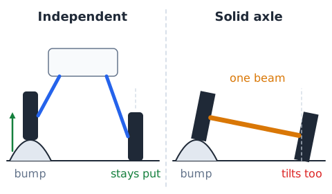
In an independent suspension, each wheel on an axle can move up and down without forcing the opposite wheel to move. This helps ride comfort and keeps each tire better planted. A solid axle ties the left and right wheels together, so a bump under one wheel tilts the other. Solid axles are strong and simple and remain common under trucks; most cars use independent designs.
Sprung and unsprung mass
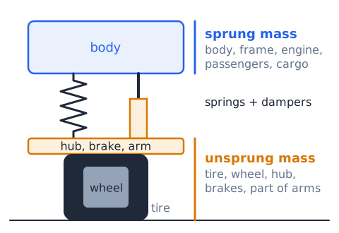
Sprung mass is everything the springs hold up: body, frame, engine, passengers and cargo. Unsprung mass is what sits below the springs and moves with the wheel: tire, wheel, hub, brakes and part of the arms and axle. Lower unsprung mass lets the wheel follow bumps faster and keeps the tire on the road more consistently.
The contact patch is where forces happen
Every steering, braking and cornering force acts through the small area where each tire touches the road. The most sideways or braking force a tire can make is roughly
where is the friction coefficient and N is the load on the tire. A tire carrying 4,000 N with
can produce about 3,200 N.
Weight transfer through corners and bumps
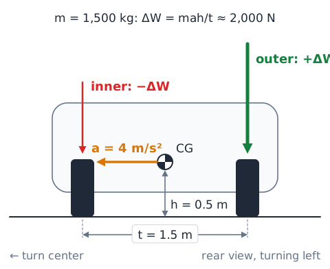
In a turn, load moves toward the outside tires. A rough estimate is
with mass m, sideways acceleration a, center-of-gravity height h and track width t. A 1,500 kg car at 4 m/s², h = 0.5 m, t = 1.5 m shifts about 2,000 N.
Steering alignment vocabulary
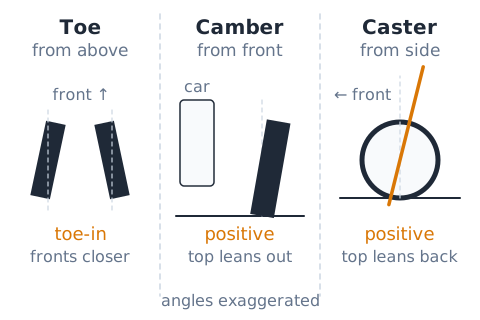
Wheel alignment means setting the angles of the wheels relative to the vehicle and the road. The three main angles are toe, camber and caster. Others include steering-axis inclination and thrust angle. Each angle is checked from a particular view and compared with the maker's specifications. Correct alignment helps the car track straight, steer predictably and wear tires evenly.
Toe: viewed from above
Toe is seen by looking down at the wheels from above. If the front edges of a pair of tires point slightly toward each other, that is toe-in. If the front edges point apart, that is toe-out. Too much toe either way makes the tires scrub sideways as they roll, causing a feathered wear pattern and faster tread loss. Toe is set by adjusting tie rod length.
Camber: viewed from the front
Camber is the tilt of the wheel seen from the front or rear of the vehicle. If the top of the tire leans outward, away from the car, camber is positive. If the top leans inward, toward the car, camber is negative. Excess camber concentrates load on one shoulder of the tread and wears that edge faster.
Caster: viewed from the side
Caster is the forward or backward tilt of the steering axis seen from the side. With positive caster, the top of the axis leans toward the rear of the car, much like the fork on a bicycle. Positive caster helps the wheels return to center after a turn and improves straight-line stability, but too much makes steering heavier. Unequal caster side to side can cause a pull.
Camber, caster, toe: view-direction drill
Look from above to judge toe. Answer: toe.
Look from the front to see the wheel tilt. Answer: camber.
Look from the side to see the steering axis tilt. Answer: caster.
Front edges apart is which? Answer: toe-out.
Ackermann geometry in a slow turn
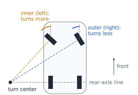
In a turn, the inside front wheel follows a smaller circle than the outside front wheel. To roll without scrubbing, it must point at a sharper angle. Steering arms are angled so that as the wheels turn, the inner wheel steers more than the outer one. This is Ackermann geometry. In a slow left turn, the left front wheel turns more sharply; in a right turn, the right front does.
Turning radius and wheelbase
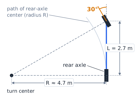
A simple bicycle model treats the car as one front and one rear wheel. At low speed, the turning radius of the rear-axle center is roughly
L is wheelbase in meters and is the front road-wheel angle. A longer wheelbase or smaller angle means a wider turn.
Turning-radius estimate
A van has a 2.7 m wheelbase and a road-wheel angle of 30°. Use the bicycle model.
The rear-axle center turns on about a 4.7 m radius; the outer front corner sweeps a larger circle.
Alignment versus balancing
Alignment and balancing are different services. Alignment adjusts angles, toe, camber and caster, so the wheels point and lean correctly; it affects pull, tracking and tire wear. Balancing corrects uneven mass around a wheel and tire by adding small weights to the rim, so the assembly spins smoothly without shaking. A shake that appears at a certain speed suggests imbalance; a steady pull or uneven wear suggests alignment, among other causes.
Pulling to one side: competing causes
A pull can come from many places. Possible causes include unequal tire pressure, a tire with internal belt problems that creates sideways force, a dragging brake, unequal caster or camber between sides, a worn or bent suspension part, and road crown, which naturally drifts cars toward the edge. A good test is swapping the front tires side to side: if the pull changes direction, a tire is a likely source.
Wear-pattern clues without overdiagnosing
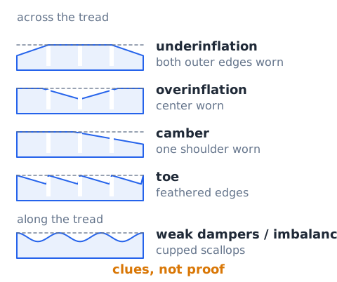
Tread wear gives hints. Wear on both outer edges often means underinflation; wear down the center can mean overinflation. Wear on one shoulder suggests a camber problem. Feathered edges point to toe. Cupped scallops suggest weak dampers or imbalance. These are clues, not proof; several causes can create similar patterns, so confirm with measurements.
Vibration, shimmy and wobble
Vibration is a shake felt in the seat, floor or steering wheel. A shake at one speed band, often 50 to 70 mph, frequently comes from an out-of-balance wheel. Shimmy is a rapid side-to-side oscillation of the front wheels, which worn tie rod ends, ball joints or loose steering parts can allow. Wobble at low speed may point to a bent wheel or a tire with a shifted belt.
Bounce test and damper limitations
A simple bounce test means pushing down hard on one corner and letting go. A healthy damper settles the body in about one cycle; continued bouncing suggests weak damping. The test is limited, though. It is slow compared to real road motion, and modern dampers may pass it while still being worn. Look also for oil leaks, cupped tires and poor control on bumpy roads.
Clunking over bumps
A clunk when driving over bumps usually means something is loose. Common sources include worn stabilizer-bar end links or bushings, worn ball joints, cracked control-arm bushings, a loose strut mount, or loose exhaust or heat-shield hardware. The sound often moves with load. Each joint should be checked for play; noises alone rarely identify the exact part.
Steering binding or sudden heaviness
If steering suddenly turns heavy, or the wheel binds and catches at certain angles, the cause could be loss of power assist, low hydraulic fluid, a slipping belt, an EPS fault, a seized ball joint or strut mount, or a damaged rack. Sudden heaviness while driving is a safety concern. The car should be stopped safely and inspected rather than driven further.
The difference between rack boot and tire boot
A rack boot is the rubber bellows on each end of the steering rack. It keeps dirt and water out of the inner tie rod joint and rack. A torn rack boot lets grit and moisture in, causing wear and rust. A tire boot is a patch placed inside a tire to cover a cut. Only the rack boot is a steering part.
Tire pressure is part of steering behavior
Inflation changes how tires handle and wear. Underinflated tires flex more, steer sluggishly, heat up and wear the outer edges. Overinflated tires ride harsh and wear the center. Use the cold pressure listed on the vehicle placard, usually on the driver's door jamb, or in the owner's manual. The number on the sidewall is the tire's maximum, not the right setting.
ESC, steering input and yaw
Electronic stability control compares where the driver is steering, from a steering-angle sensor, with how the car is actually rotating, from a yaw-rate sensor. If the car turns less or more than the driver asks, ESC brakes individual wheels and may reduce engine power to bring the car back in line. It cannot exceed the tires' grip.
Understeer versus oversteer
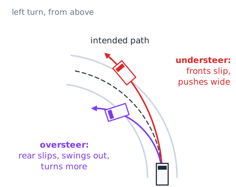
Understeer means the front tires reach their grip limit first; the car turns less than the driver steers and pushes wide. Oversteer means the rear tires lose grip first; the rear swings out and the car turns more than intended. In slip-angle terms, understeer is when the front slips more than the rear,
and oversteer is
Most cars are tuned toward mild understeer.
Steer-by-wire design exception
Most cars keep a mechanical connection between steering wheel and road wheels. Steer-by-wire is an exception: sensors read the steering wheel, and electric motors move the rack with no direct shaft linking the two. A separate motor gives the driver road feel. Because the mechanical link is absent, these systems use redundant sensors, controllers and power supplies. Exam questions about conventional cars assume a mechanical link.
Workshop safety around suspension springs
A compressed coil spring, torsion bar or leaf pack stores a great deal of energy, even with the vehicle lifted. If it is released carelessly, it can fly apart with deadly force. Strut and spring removal is a task for trained technicians using proper, undamaged equipment and the manufacturer's procedure. Never support a vehicle on a jack alone. Learners should observe rather than attempt it.
Why manufacturer specifications matter
Each vehicle has its own alignment angles, tightening torques, spring rates, ride heights and fluid types, developed for its weight and geometry. Using another vehicle's numbers, or guessing, can cause poor handling, fast tire wear or part failure. Technicians follow the maker's published specifications and procedures, and many suspension bolts are tightened only at normal ride height.
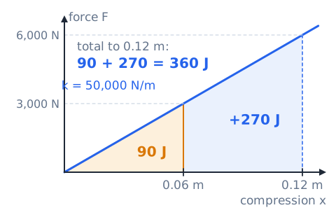
Spring energy example
A spring with
N/m compresses 6 cm. How much energy does it store?
Convert: 6 cm = 0.06 m.
At 12 cm, twice the compression:
four times as much.
Damping and energy comparison
A spring stores energy and gives it back; a damper turns energy into heat. Ideal damping force is proportional to velocity.
With
N·s/m, a wheel moving at 0.3 m/s meets 600 N; at 0.6 m/s, 1,200 N. Spring force follows position; damper force follows speed.
Quick classification: name the component
It slides side to side and moves the tie rods. Answer: the rack.
It lets a hub spin with little friction. Answer: the wheel bearing.
It turns oil flow into heat to stop bouncing. Answer: the damper.
It twists to resist uneven left-right travel. Answer: the anti-roll bar.
It carries the hub and pivots for steering. Answer: the steering knuckle.
Quick classification: pick the view
Top of tire tilts inward. Answer: negative camber, front view.
Front edges point toward each other. Answer: toe-in, view from above.
Steering axis top leans rearward. Answer: positive caster, side view.
Quick classification: no single symptom is a verdict
A car pulls right. Only one cause? Answer: no; tires, pressure, brake drag and alignment all qualify.
Body bounces after bumps. Most likely area? Answer: dampers.
Shake at 60 mph only. First candidate? Answer: wheel imbalance, though a bent wheel or tire defect could also cause it.
How to approach ASVAB Auto Information
Read the stem for the function being asked about, such as supporting load, damping motion, or turning the wheels, then match it to the part designed for that job. Eliminate choices from unrelated systems, such as brakes, cooling or ignition. For alignment items, identify the viewing direction first. For calculations, convert units, then check whether the answer is sensible.
Safe and precise technical language
Good answers use careful words. A symptom suggests or is consistent with a cause; it rarely proves one. Say a shock absorber damps motion rather than holds the car up. Say power steering reduces effort rather than steers the car. On safety, say a technician with proper equipment should do spring and steering work. Absolute words like always or never often mark a wrong answer.
Four common ASVAB distractors
Distractor one: shock absorbers support the vehicle's weight; springs do. Two: balancing and alignment are the same; they are not. Three: power steering steers on its own; it only assists. Four: the sidewall number is the correct inflation; use the placard.
Case: clunk and unequal tire wear
A sedan clunks over potholes, and the right front tire is wearing on its inner shoulder.
Analysis: the clunk suggests looseness, such as a worn ball joint, control-arm bushing or end link. Looseness can let the wheel tilt or toe under load, which fits the uneven wear. The parts should be inspected for play, worn items replaced and the alignment then checked against specifications.
Case: heavy wheel at low speed
A hatchback's steering suddenly feels very heavy while parking, though it seems acceptable at highway speed.
Analysis: assist is strongest at low speed, so loss of assist shows up most there. Candidates include an EPS fault, low hydraulic fluid or a slipping pump belt, or a binding strut mount or ball joint. The car can still steer mechanically, but a technician should find the cause before regular use.
Case: bounce with normal ride height
A minivan sits level at normal height but keeps bobbing after dips in the road, and the tires show cupped wear.
Analysis: correct ride height means the springs are holding the load. Continued bouncing and cupping point to worn dampers that no longer control motion. Replacing the dampers in axle pairs is the usual fix.
Case: vibration after replacing tires
After new tires were mounted, a car shakes through the steering wheel near 65 mph but drives straight and smooth at lower speeds.
Analysis: a speed-specific shake right after tire service points first to an out-of-balance wheel, such as a missing or misplaced weight, or a tire not seated evenly. Alignment is a separate service and usually affects pull and wear, not a speed-band shake. The wheels should be rebalanced and checked for runout.
Final steering and suspension memory map
Steering path: wheel, column, pinion, rack, tie rods, knuckle. Springs hold weight; dampers control bounce; anti-roll bar limits roll; ball joints and bushings pivot. Toe from above, camber from the front, caster from the side. Balancing fixes mass; alignment fixes angles. Leave spring work to trained technicians.
road angle = wheel angle / ratio,
 English ▾