 ASVAB Camp
Learning goals
By the end of this lesson you should be able to explain how the battery, starter and alternator share the work of a conventional 12-volt system, and how fuses, relays and grounds fit into each circuit. You will use Ohm's law and the power formula on simple series and parallel circuits, estimate battery energy, and sort diagnostic clues into "suggests" versus "proves," while knowing which jobs belong to trained technicians.
Three jobs: store, start and replenish
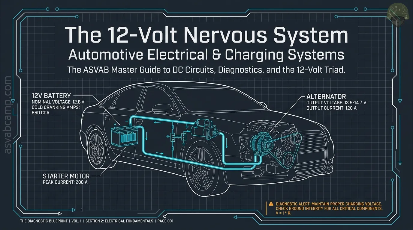
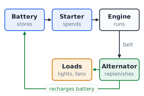
A conventional car's electrical system does three jobs. The battery stores energy in chemical form so it is ready when the engine is off. The starter motor spends a large burst of that stored energy to spin the engine fast enough to begin running. Once the engine runs, a belt turns the alternator, which generates electricity for the lights, computers and fans and also recharges the battery. If any one job fails, the other two cannot cover for it for long.
Conventional 12-volt scope
This lesson describes the ordinary gasoline or diesel vehicle with a 12-volt lead-acid battery and a belt-driven alternator, the system most ASVAB Auto Information questions assume. Hybrids and electric vehicles add high-voltage battery packs, often several hundred volts, that use different hardware and serious shock precautions. Those systems are outside this lesson, and their orange high-voltage cables should be left entirely to trained technicians.
A circuit must be complete
Current flows only around a closed loop: from the source, through the wiring and the load, and back to the source. Break the loop anywhere and current stops everywhere in that loop. An open switch, a blown fuse, a broken wire or a loose connector all create an open circuit. That is why a dome lamp goes dark when the door switch opens, even though the bulb, the battery and the rest of the wire are perfectly fine.
Electrical pressure, rate and opposition
Three quantities describe every circuit. Voltage, measured in volts (V), is the electrical push, the potential difference between two points. Current, measured in amperes (A), is the rate at which charge flows past a point. Resistance, measured in ohms (), is how strongly a part opposes that flow. A water comparison helps: voltage is like pressure, current like the flow rate, and resistance like a narrow pipe. With 12 V pushing through an 8 heater element, the current is
Ohm’s law for an ideal resistance
For an ideal resistor, voltage, current and resistance are tied together by Ohm's law.
Here V is voltage in volts, I is current in amperes and R is resistance in ohms. Rearranged,
Quick use: a 14 V supply across a 7 part gives
Real lamps and motors change resistance as they heat, so treat this as a model.
Power in DC circuits
Electrical power is the rate of energy use, measured in watts (W).
P is power in watts, V is volts and I is amperes. Substituting Ohm's law gives two other forms,
Example: a fan motor drawing 5 A from 12 V uses
Working backward,
so a 24 W accessory at 12 V draws 2 A.
Conventional current versus electron flow
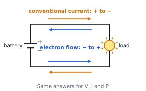
Diagrams and textbooks usually show conventional current, which is drawn leaving the positive terminal, passing through the load and returning to the negative terminal. In metal wires the moving charges are actually electrons, which drift the opposite way, from negative toward positive. Both descriptions give the same answers for voltage, current and power. Just stay consistent with whichever convention a question uses.
Body ground and return paths
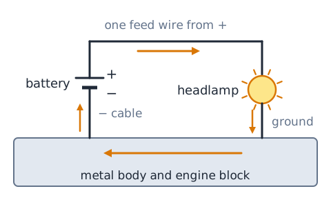
Most vehicles use a negative-ground design. The battery negative cable bolts to the engine block and the body, so the metal structure becomes a shared return conductor. A headlamp, for example, needs only one feed wire from positive; its return path goes through a ground wire or mounting bolt into the body and back to battery negative. That return path is part of the circuit and has resistance like any wire. If a corroded ground strap has 0.002 and the starter draws 150 A, the strap alone drops
which the starter never receives.
Series versus parallel connections
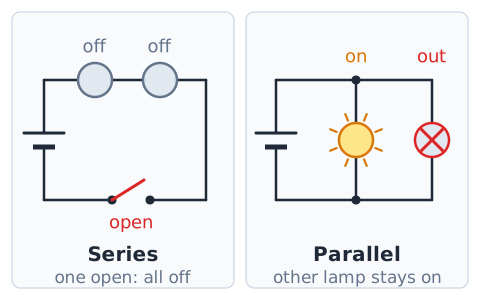
In a series connection, parts sit one after another on a single path, so the same current flows through each and an open anywhere stops all of them. In a parallel connection, each part has its own branch connected across the same two points, so each branch gets the full supply voltage and can work or fail on its own. Vehicles wire most lamps and accessories in parallel for this independence.
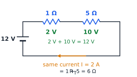
Series resistance and current
In series, resistances simply add.
The single current is
Example: 1 and 5 in series on 12 V give
The drops are 2 V and 10 V, which add back to 12 V.
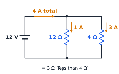
Parallel branch rules
Every parallel branch sees the full supply voltage, and branch currents add. The equivalent resistance is found from
Example on 12 V: branches of 12 and 4 carry 1 A and 3 A, for 4 A total, and
The equivalent is always smaller than the smallest branch.
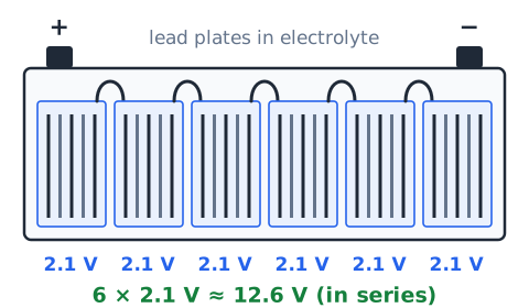
What the battery stores
A battery does not store electricity the way a tank stores fuel. It stores chemical energy. In a lead-acid battery, lead plates sit in a sulfuric-acid electrolyte. During discharge, a chemical reaction pushes electrons out through the external circuit; during charging, current forced back in reverses that reaction. A 12-volt battery contains six cells of roughly 2.1 V each connected in series, giving about 12.6 V when fully charged and rested.
Battery capacity versus starting ability
Two ratings describe different abilities. Amp-hour (Ah) capacity tells how much charge the battery can deliver slowly, often tested over 20 hours. A 60 Ah battery on that test supplies about
for the full 20 hours. Cold-cranking amps (CCA) describe a short, violent demand: the current a new battery can deliver for 30 seconds at 0 F (about C) while staying at or above 7.2 V. A battery can have generous Ah yet modest CCA, or the reverse, so neither number replaces the other.
Idealized ampere-hour arithmetic
In the simple model, runtime equals capacity divided by current.
t is time in hours, C is capacity in ampere-hours and I is a steady current in amperes. Example: a 40 Ah battery feeding a constant 2 A load lasts
Real batteries deliver less at high currents, in cold weather and with age, and a starting battery should never be run flat.
Watt-hours and energy
Ampere-hours measure charge; watt-hours measure energy. Multiply by voltage to convert.
E is energy in watt-hours (Wh), V is nominal voltage and C is capacity in Ah. A 12 V, 60 Ah battery holds about
or 0.72 kWh. In the ideal model a steady 100 W load would empty it in
h. In reality, usable energy is far lower, because deep discharge harms a starting battery.
State of charge is not battery health
State of charge tells how full the battery is right now. State of health tells how much the battery can still do compared with when it was new. An old battery can be fully charged yet collapse under a cranking load because its plates are worn or sulfated. A healthy battery can be nearly empty after the lights were left on. A voltage reading alone mostly reflects charge; a load or conductance test is needed to judge health.
Open-circuit voltage must rest
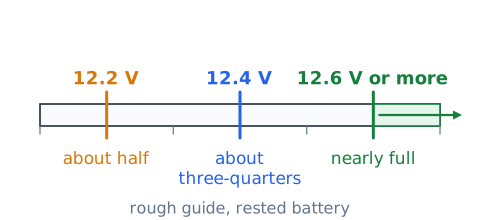
Open-circuit voltage is measured with no load and no charging. Right after driving or charging, a thin "surface charge" makes the battery read higher than its true state. Let it rest, or briefly switch on a light to remove the surface charge, before reading. As a rough guide for a rested lead-acid battery, about 12.6 V or more suggests nearly full, around 12.4 V suggests roughly three-quarters, and near 12.2 V suggests about half.
The battery positive distribution path
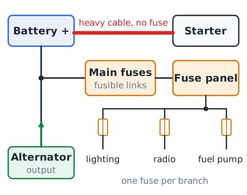
From the battery positive post, a heavy cable runs directly to the starter, usually with no fuse because starter current is so large. Another path goes to a main fuse box, where large fuses or fusible links feed smaller fuse panels. From there, fuses protect individual branches such as lighting, the radio or the fuel pump. The alternator output also connects into this positive network so it can supply loads and recharge the battery.
Battery cables are part of the system
The thick positive and negative battery cables carry hundreds of amperes during cranking, so even a tiny resistance matters. Corrosion at a clamp, a cable that is broken inside its insulation, or a loose terminal bolt can waste enough voltage to make a good battery crank slowly. A cable can look fine and still have internal damage. That is why technicians judge cables by a voltage-drop test under load, not only by appearance.
Starter motor job
The starter is a powerful DC electric motor that turns electrical energy into rotation. Its small pinion gear meshes with a large ring gear on the engine's flywheel or flexplate, giving a high gear reduction so the motor can spin the crankshaft fast enough for the engine to fire. It may draw well over 100 A, and it is designed to run only for short periods.
Solenoid and pinion engagement
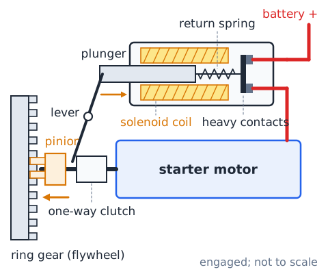
The starter solenoid is an electromagnet with two jobs. When energized, its plunger pushes the pinion forward into mesh with the ring gear. At the same moment it closes heavy internal contacts that connect battery current to the motor. When the key or button is released, a spring pulls the pinion back, and a one-way clutch keeps the running engine from spinning the starter too fast.
Start request and interlocks
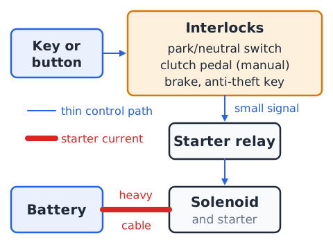
Turning the key or pressing the start button sends a small control signal, not the starter current itself. That signal usually passes through safety interlocks before it reaches the starter relay or solenoid. A neutral safety or park switch blocks starting in gear on automatics, and many manuals need the clutch pedal pressed. On newer cars, a computer may also check the brake pedal and the anti-theft key before allowing a crank.
Click, crank and start are different
Separate three outcomes. A click without cranking means the solenoid or relay responded but the motor did not turn, which points toward low battery voltage, poor cables or connections, or a starter fault. Cranking means the starter spun the engine, so the starting circuit largely works. Starting means the engine fired and ran on its own, which also needs fuel, spark or compression ignition, and air. A strong crank with no start points to those other systems, not the starter.
Alternator versus starter motor
The starter and the alternator both contain coils and magnets, but they work in opposite directions. The starter is a motor: it takes electrical energy from the battery and produces mechanical rotation, only during starting. The alternator is a generator: it takes mechanical rotation from the engine belt and produces electrical energy, the whole time the engine runs. Mixing them up is a common exam trap.
Alternator electromagnetic induction
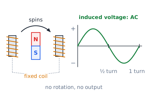
An alternator works by electromagnetic induction. When a magnetic field moves relative to a coil of wire, a voltage is induced in that coil. In the alternator, the engine belt spins an electromagnet inside fixed coils, so the field sweeps past the windings over and over. Each pass reverses the field direction the coils see, which is why the raw output is alternating current (AC). No rotation means no output.
Rotor, stator, rectifier and regulator
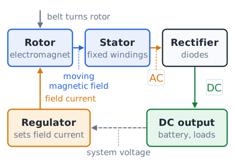
The rotor is the spinning electromagnet; a small field current reaches it through brushes and slip rings. The stator is the set of stationary windings around the rotor, and the AC is induced there. The rectifier, a set of diodes, converts that AC into DC for the vehicle. The voltage regulator controls rotor field current, raising or lowering output so the system voltage stays in its target range.
Why diodes matter
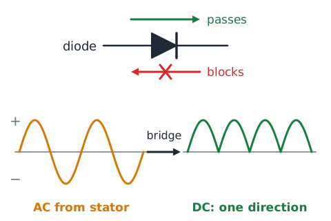
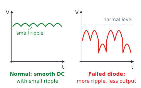
A diode lets current pass in one direction and blocks it in the other, like a check valve in a water line. Arranged in a bridge, the alternator's diodes steer every half of the AC wave in the same direction, producing DC. They also stop the battery from pushing current back through the stator when the engine is off. A failed diode can cut output and let AC ripple into the system.
Voltage regulation and modern control
Without regulation, alternator voltage would rise with engine speed and could overcharge the battery and damage electronics. The regulator adjusts the rotor's field current to hold output in a target band, often somewhere in the range of about 13.5 to 14.7 V on a conventional car. Many modern vehicles let the engine computer set that target, changing it with temperature, battery condition and electrical load, so the right reading depends on the vehicle.
The alternator does not make free energy
An alternator converts energy; it does not create it. Every watt it delivers comes from the engine through the belt, plus extra to cover losses. The input power needed is
where (eta) is efficiency, a fraction less than 1. When you switch on heavy loads such as a rear defroster and blower, the regulator raises field current, the alternator becomes harder to turn, and the engine must burn a little more fuel. That is why electrical load affects fuel economy.
Alternator load power example
Electrical output power is bus voltage times current.
Suppose the system runs at 14 V while the alternator delivers 50 A to lights, fans and the battery.
That 700 W is the electrical output only, not what the engine must supply.
Mechanical input and efficiency
Efficiency compares useful output to input.
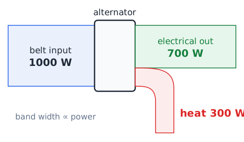
Continuing the 700 W example with an assumed efficiency of 0.70:
The belt must deliver about 1000 W, and the missing 300 W become heat in the alternator.
Charging light is not a battery-condition verdict
The battery-shaped warning lamp is really a charging-system lamp. When it lights with the engine running, it signals that the system is not charging as expected, perhaps from a slipping belt, a failed alternator or a wiring fault. It does not directly measure the battery's health or charge. The practical meaning is that the battery may be draining, so the charging system needs inspection soon.
Ripple and charging-quality concepts
Rectified alternator output is never perfectly smooth DC. A small leftover wiggle, called ripple, rides on top, and the battery helps absorb it. If a diode or stator winding fails, ripple can grow and output drop. Excess ripple may cause flickering lights, radio noise or confused electronics. It is a clue that justifies testing the rectifier, but a scope or alternator tester is needed to confirm.
Fuse versus relay
A fuse and a relay sit in the same fuse box but do different jobs. A fuse is a protective device: a calibrated metal strip melts and opens the circuit when current exceeds its rating, protecting the wiring from overheating. A relay is a switch: a small control current energizes a coil that closes or opens a separate set of contacts. A fuse decides when current is dangerous; a relay decides when a load should run.
Fusible links and high-current protection
Large feeds near the battery need protection too. A fusible link is a short section of special wire, smaller than the circuit it protects, with insulation that will not burn; during a severe overload it melts open. Many newer vehicles use high-amp cartridge fuses, often called maxi or mega fuses, for the same role. Either part must be replaced only with the exact type and rating specified, after the fault is found.
Switches and loads in a basic circuit
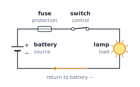
A basic circuit contains a source, protection, a control and a load, joined by conductors. The source is the battery or alternator, the protection is a fuse, the control is a switch and the load is whatever does the work, such as a lamp, motor or heater. The load is where most of the voltage is used. A closed switch completes the path; an open switch interrupts current through that path.
What a relay coil controls
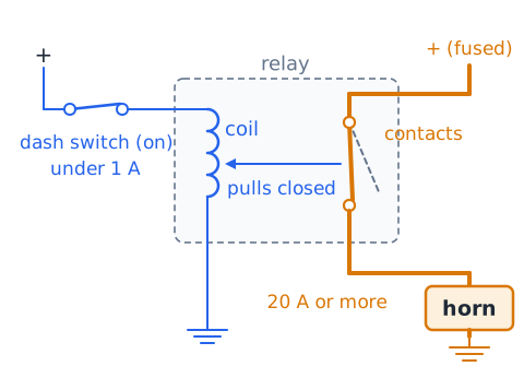
A relay has two separate circuits. The control side is a light coil energized by a dash switch or computer output using only a fraction of an ampere. The load side is a pair of heavy contacts that the coil's magnetism pulls closed, feeding perhaps 20 A or more to a horn, fan or fuel pump. This lets small switches and thin wires command big loads.
Ground fault versus short-to-power
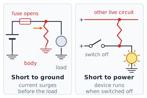
A short to ground happens when a powered wire touches the body or another ground before reaching its load. Resistance collapses, current surges and the fuse should open. A short to power happens when a wire touches another live circuit, so a device may run when it should be off or two circuits feed each other. The symptoms differ, so name the fault type before testing.
Electrical resistance changes with temperature
The resistance of metal conductors rises as they get hotter. A lamp filament, for example, has low resistance when cold, so it draws a surge of current at switch-on before it heats and settles. Wires and connections that run hot also lose a little more voltage. Battery chemistry works the other way in the cold: reactions slow and internal resistance rises, which is why cranking is harder in winter.
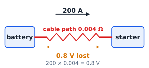
Voltage drop across a resistive cable
Any conductor carrying current loses some voltage along its length.
I is current in amperes and R is the cable or connection resistance in ohms. Example: 200 A of cranking current through a cable path of 0.004 loses
before reaching the starter.
Heat dissipated in a bad connection
Power lost in a resistance becomes heat.
P is watts, I is amperes and R is ohms. A corroded connection of 0.04 carrying 50 A dissipates
That is concentrated in one small joint, enough to melt insulation and start a fire.
Battery terminal voltage under a load
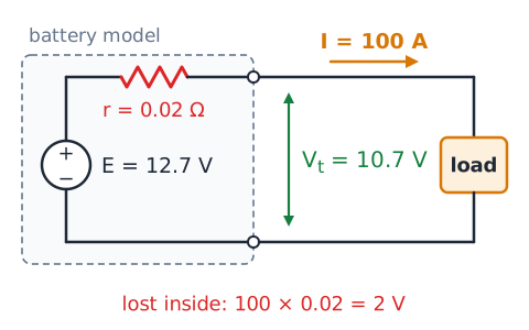
A battery is not a perfect voltage source. It has a small internal resistance, so when it delivers current, some voltage is lost inside it and the terminal voltage sags. During cranking a healthy 12-volt battery may briefly dip to around 10 V and still be fine. A weak or discharged battery sags much further, which is why a load test reveals problems that a resting voltage check can hide.
Simple source with internal resistance
Model the battery as an ideal voltage E in series with an internal resistance r.
is terminal voltage, E is the no-load voltage, I is load current and r is internal resistance in ohms. Example: E = 12.7 V, r = 0.02 , I = 100 A.
DC multimeter: voltage mode
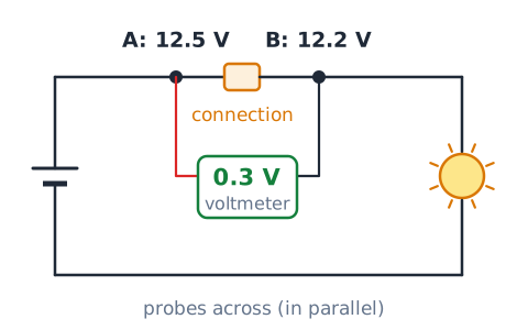
In DC volts mode, a multimeter reports the potential difference between the points touched by its two probes. It is connected across, or in parallel with, whatever you measure, and its very high input resistance means it draws almost no current. It does not measure stored ampere-hours or cranking ability. The reading is simply the difference between the two points:
If one probe touches a point at 12.5 V and the other a point at 12.2 V, the meter shows 0.3 V. Measuring across a single connection while current flows is how a voltage-drop test finds a hidden resistance.
DC multimeter: current mode and clamp meters
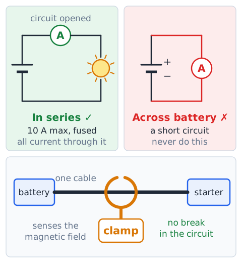
To measure current with an ordinary meter, the circuit must be opened and the meter inserted in series, so all current flows through it. Its current range is fused and usually limited to about 10 A, and connecting it across a battery like a voltmeter creates a short. Large currents, such as starter draw, are measured with an inductive clamp meter instead. It senses the magnetic field around a single conductor without breaking the circuit.
Resistance and continuity require isolation
An ohmmeter supplies its own small test current, so the part being tested must be unpowered and usually disconnected. Live voltage gives false readings and can damage the meter, and other parallel paths can make a broken part look good. A continuity beep proves only that some path exists. It cannot prove that a cable will carry hundreds of amperes; a few damaged strands still beep.
Interpreting apparent parasitic draw
Parasitic draw is the small current a parked car uses for clocks, alarms and module memory. Right after the doors close, many computer modules are still awake, so the first reading may be far higher than normal. Modules can take from a few minutes to an hour to go to sleep. Judge the draw only after they settle, then compare with the maker's limit, often tens of milliamps. A high reading tells you to look further, not which circuit is guilty.
Voltage-divider caution
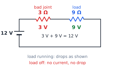
When resistances share one series path, the supply voltage divides among them in proportion to their resistance.
With 12 V across 3 and 9 , the 9 part gets
The caution: an unwanted resistance in a circuit forms a divider with the load. With the load off or disconnected, the bad joint carries no current, so the meter can show full voltage past it. Once the load runs, the bad joint takes its share and the load starves. Test under load.
Reading wiring diagrams systematically
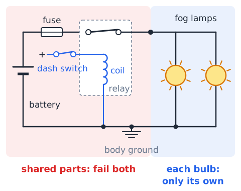
Read a wiring diagram as a path, not a picture. Start at the power source and its fuse, follow the feed through each switch, relay contact or connector to the load, then trace the return through the ground point back to battery negative. Note wire colors, connector numbers and ground locations along the way. Asking "what must be closed for current to reach this load?" turns a dense diagram into a short checklist.
A lighting branch as a complete example
Picture a simple fog-lamp branch. Battery positive feeds a fuse, then the contacts of a relay. The relay coil is energized by a dash switch. When the coil pulls in, current flows through the contacts to both fog lamps, which sit in parallel, then from each lamp to a body ground and back to battery negative. A failure of the fuse, relay, switch, feed wire or shared ground can darken both lamps; a failed bulb darkens only its own.
Independent headlights in parallel
Two headlamps wired in parallel each receive the full system voltage. Each lamp's current is
For two ideal 60 W lamps on 12 V, each draws
and the shared feed carries
If one lamp burns out, the other keeps its 5 A and stays lit.
Engine-off and engine-running observations
Compare readings across the battery with the engine off and with it running. A rested battery near 12.6 V is roughly full. With the engine running, the voltage should rise noticeably above the resting value as the alternator takes over, typically into the 13s or 14s depending on the vehicle. If the running voltage stays at or below the engine-off value, the charging system is not keeping up and deserves inspection.
Distinguish no-crank from slow-crank
No-crank means the engine does not rotate at all. Look at the start request, interlocks, relay, solenoid, starter or a nearly dead battery. Slow-crank means the engine turns, but sluggishly. That points to low battery charge, poor battery health, high resistance in cables or grounds, cold thick oil or a dragging starter. Naming which one you have narrows the search before any part is replaced.
Belt and pulley problems
The alternator can only produce as much as the belt lets it turn. A glazed, worn, stretched or oil-soaked belt can slip under heavy electrical load, often with a squeal, and charging output may drop. A weak automatic tensioner or a misaligned or noisy pulley causes similar trouble. Visual belt checks are done with the engine off; belt and tensioner replacement follows the service manual.
Why corrosion matters
Corrosion is a poor conductor. The white, green or bluish crust on battery terminals, ground straps and connectors adds resistance exactly where large currents pass. Under load that resistance wastes voltage and makes heat, so a car may crank slowly, charge poorly or have flickering accessories even with a good battery. Corrosion can also hide inside a cable end or connector where it cannot be seen.
Battery chemistry and repair boundaries
A lead-acid battery contains sulfuric acid, which burns skin and eyes, and lead, which is toxic. Flooded, enhanced flooded (EFB) and absorbed glass mat (AGM) designs each have their own charging needs. A battery is never opened, refilled with acid or rebuilt by an owner. A cracked, swollen or leaking battery is replaced, and old batteries go to a recycling collection point. High-voltage hybrid and EV packs are for trained technicians only.
Safe work around a battery
Charging and discharging can release hydrogen gas, which is explosive, so keep flames, sparks and smoking away and work with good ventilation. Wear eye protection and gloves, since acid can spatter. Remove rings, watches and metal jewelry, and never let a wrench bridge the two terminals or touch positive and the body at once. Follow the vehicle manual's order for disconnecting and connecting cables and for any jump-starting, since many modern vehicles have specific steps.
Why an incorrect fuse is unsafe
A fuse's rating is chosen to protect the wire behind it. If a fuse keeps blowing, something is drawing too much current. A higher-rated fuse, foil or a jumper does not fix that; it lets the wire carry dangerous current until the insulation melts or a fire starts. The fault must be diagnosed, and the fuse replaced only with the specified type and rating.
A logical no-charge investigation
A no-charge complaint is worked from simple to complex. Confirm the symptom: the warning lamp, and running voltage that does not rise above engine-off voltage. Next, look for the obvious, such as a missing, loose or slipping belt, corroded or loose cables, and blown fuses. Then check whether the alternator receives its control signals and whether its output reaches the battery. Only after these steps does replacing the alternator make sense.
High-current circuits deserve extra care
The starter cable, alternator output wire and main battery feeds carry very large currents and are often unfused or protected only by big fuses. A short in them can weld tools, burn skin and start fires within seconds. Rings and metal watch bands can heat red-hot if they bridge a live terminal and ground. Keep these circuits for qualified work and follow the vehicle's service procedures.
Smart charging and stop-start caveat
Many newer vehicles use smart charging. The engine computer, often helped by a current sensor on the battery cable, varies alternator output, sometimes letting voltage fall to save fuel and raising it during braking. Stop-start vehicles shut the engine off at stops and typically need AGM or EFB batteries, and some require the new battery to be registered with the computer. On these cars, an older fixed voltage rule of thumb may be misleading.
Typical diagnostic decision table
Match the symptom to the area to check first. Click but no crank suggests low battery, poor cables or connections, or the starter and solenoid. Slow crank suggests battery charge or health, cable and ground resistance, or cold oil. A normal crank with no start points to fuel, ignition or engine control, not starting. A charging lamp while running points to the belt, alternator or its wiring. A battery that is dead after parking points to charging or parasitic draw. Each is a starting point, not proof.
Current shared by parallel loads
Total current in a parallel circuit is the sum of the branch currents.
Each branch current is . On 12 V, a 6 branch draws 2 A and a 12 branch draws 1 A, so the shared feed carries 3 A. The lower-resistance branch takes the larger share.
A design current and fuse misconception
You can estimate a load's normal current from its power,
A 150 W blower on 12 V draws
A common mistake is to pick a fuse from that arithmetic, or to go bigger if one blows. The specified fuse rating is set by the manufacturer to protect that circuit's wire size and parts. Always use the rating shown on the fuse panel or in the manual.
Series voltage-drop reasoning in practice
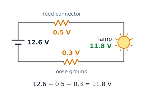
Around any single loop, the voltage drops add up to the source voltage. In a real lamp circuit, the wiring and connections are small series resistances. Suppose the battery supplies 12.6 V, a corroded feed connector drops 0.5 V and a loose ground drops 0.3 V. The lamp then receives
so it glows dimmer. Measuring each drop under load shows exactly where voltage is lost.
Parallel-current reasoning in practice
Every load added in parallel adds its current to the shared feed. Suppose one fuse and wire feed three accessories drawing 4 A, 6 A and 8 A. With all three on, the shared feed carries
Adding parallel loads lowers total resistance and raises total current. An aftermarket accessory spliced into such a circuit can push it past its rating.
Efficiency and losses are physical
No machine converts all its input into useful output; the rest appears mostly as heat. Suppose a starter takes in 10.5 V at 200 A:
If it delivers 1260 W of mechanical power, then
and about 840 W heat the motor. That heat is why cranking should be done in short bursts.
Worked scenario: slow crank and dim lamps
On a cold morning, a driver turns the key and the engine turns over slowly while the dash lights dim sharply. The engine finally starts. Analysis: the starter receives power, so the request and solenoid work. Dimming means system voltage is sagging under the cranking load. The likely areas are low battery charge, a weak battery, or high resistance in cables or grounds. A load test and voltage-drop checks come next.
Worked scenario: start succeeds then battery light
A car starts normally, but the battery warning lamp stays on while driving. Analysis: the battery had enough energy to start, so starting is not the issue. The lamp indicates the charging system is not keeping up, so the car is running on stored battery energy, which will run out. Check the belt, then measure running voltage, then test the alternator and its wiring.
Worked scenario: intermittent accessory
A power outlet works only sometimes and quits when the car hits bumps. Analysis: the outlet clearly works when its circuit is complete, so the fault is likely a connection that opens with movement, such as a loose connector pin, a cracked solder joint or a corroded ground. Wiggling harness sections while watching the outlet or a meter can locate it. Replacing the fuse with a larger one would not help.
Misconception audit
Check each belief. "The alternator charges the battery so the car runs free of fuel cost" is false; the engine pays for every watt. "A bigger fuse is safer" is false; it protects the wire less. "12.6 V proves a good battery" is false; voltage reflects charge, not health. "Ground wires do not matter" is false; returns carry full current. "A continuity beep proves a cable is good" is false under heavy load.
Self-check: identify the complete paths
Test yourself. A horn has a fuse, relay contacts, the horn and a ground. What completes its load path? Answer: battery positive, fuse, closed relay contacts, horn, ground, battery negative. A parking lamp's ground screw rusts loose. Answer: that lamp's return path opens, so it stays dark. The dash switch opens on a relay-controlled circuit. Answer: the coil de-energizes, the contacts open and the load stops.
Exam strategy: reject absolute claims
Diagnostic answers that use words like "always," "never," "certainly" or "proves" are usually wrong, because a single symptom rarely has only one possible cause. Prefer answers that name the most likely system and recommend checking it, such as "inspect the charging system." On calculation questions, write the formula, plug in units and check that the result is reasonable. A 12 V circuit drawing 576 A from one accessory should look suspicious.
Key terms
Voltage is electrical push between two points, in volts. Current is the rate of charge flow, in amperes. Resistance opposes flow, in ohms. Power is the rate of energy use, in watts. A starter converts electricity into crankshaft rotation; a solenoid engages its pinion and switches its current. An alternator generates electricity; its stator holds the windings and its diodes rectify AC into DC. A fuse protects; a relay switches. CCA rates cold cranking; Ah rates capacity.
Final recall and boundaries
The battery stores, the starter spends and the alternator replenishes. Every circuit needs a complete path, including the ground return. Use
with series and parallel rules for calculations. Treat symptoms as clues that point to a system, not as final verdicts. Battery work demands eye protection and spark control, fuses must keep their specified rating, and high-current and high-voltage work belongs to trained technicians.
 English ▾