 ASVAB Camp
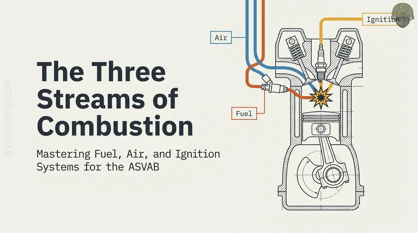
Lesson objective and Auto Information relevance
In this lesson you will learn how an engine gets the three things it needs to burn fuel usefully: fuel, air and a way to ignite the mixture. You will compare gasoline and diesel combustion, trace fuel and intake paths, and see how sensors feed an engine control module that commands injectors and spark.
You will also practice short calculations of air-fuel ratio, lambda and ignition timing. The Auto Information test often asks what a named part does or which system a symptom points to, so clear function-by-function thinking pays off.
Three requirements for useful engine combustion
An engine turns chemical energy in fuel into motion by burning it inside closed cylinders. For that burn to happen and produce useful force, three things must come together at the right moment: fuel, oxygen supplied by air, and an ignition source.
Remove any one and combustion stops. A car with an empty tank has air and spark but no fuel. A clogged air filter starves the engine of oxygen. A failed coil leaves a gasoline engine with fuel and air but no spark. The amounts and timing also matter: the right proportion of fuel to air, ignited at the right point in the piston's travel, gives smooth power.
Follow the energy and flow rather than memorizing one part
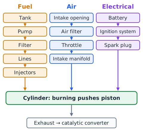
Instead of memorizing parts in isolation, trace what moves through the engine. Fuel travels from the tank through a pump, filter and lines to the injectors. Air travels from the intake opening through the air filter, past the throttle and into the intake manifold. Electrical energy travels from the battery through the ignition system to the spark plug.
These streams meet in the cylinder, where burning releases heat that pushes the piston. Exhaust then leaves past the catalytic converter. When a test question names a part, ask which stream it belongs to and what it does to that stream: store, move, clean, measure, meter or ignite.
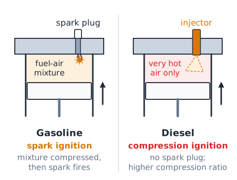
Gasoline versus diesel ignition is a fundamental distinction
A gasoline engine is a spark-ignition engine. Its fuel-air mixture is compressed, and then a timed electric spark from the spark plug starts the burn.
A diesel engine is a compression-ignition engine. It squeezes air alone so tightly that the air becomes very hot, often well above the temperature at which diesel fuel self-ignites. Fuel is then sprayed into that hot air and ignites on its own, with no spark plug needed. Diesels therefore use much higher compression ratios. Glow plugs in some diesels only help cold starting; they are not a timed spark for every cycle. The key difference is how ignition begins, not merely where fuel enters.
Identify the fuel tank without giving it another job
The fuel tank is a storage container. It holds the vehicle's supply of fuel and keeps it sealed against leaks and vapor escape. In many modern cars the electric fuel pump and a fuel-level sending unit are mounted inside the tank, but those are separate parts with their own jobs.
The tank does not pressurize fuel for the injectors, does not filter air and does not measure the mixture. Its vent and evaporative emission connections let vapors be captured rather than released. On a test, if a choice says the tank meters fuel or creates spark, reject it; the tank's role is simply to store fuel safely.
Fuel pump, fuel line and rail are a delivery chain
Think of fuel delivery as a chain of links. The fuel pump, usually electric and often inside the tank, moves fuel and raises its pressure. Fuel lines carry it from the tank toward the engine. A filter along the way catches debris. At the engine, the fuel rail is a pipe or manifold that holds pressurized fuel and feeds each injector.
A pressure regulator or the control module keeps rail pressure within the designed range. Each link has a separate job: the pump creates flow and pressure, the lines carry it, and the rail distributes it. None of them decides how much fuel enters a cylinder; that is the injector's job.
What a fuel filter actually removes
A fuel filter traps solid contaminants such as rust flakes, dirt and debris before they reach the precise passages of the pump, regulator or injectors. Some vehicles have a coarse strainer, often called a sock, on the pump inlet plus a finer filter downstream; others combine them in a pump module.
Diesel systems often add a water separator because water in diesel fuel damages injection parts. A fuel filter does not clean air, does not remove exhaust pollutants and does not change octane. A badly clogged fuel filter can restrict flow, which may cause hesitation or lean running under heavy load.
Fuel injectors meter rather than continuously spray
A fuel injector is an electrically operated valve. When the engine control module energizes it, a solenoid or piezo element opens the nozzle and pressurized fuel sprays out as a fine mist. When the signal ends, the injector closes.
The amount of fuel delivered depends mainly on fuel pressure and how long the injector stays open, called pulse width, usually a few milliseconds. By lengthening or shortening the pulse, the controller meters exactly the dose each cylinder needs. So an injector is a metering device that opens in timed bursts, not a hose that sprays nonstop. It neither makes the spark nor measures oxygen.
Port injection: where the fuel enters
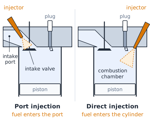
In port fuel injection, each cylinder has an injector mounted in the intake manifold or head so that it sprays into the intake port, just upstream of the intake valve. Fuel mixes with incoming air in the port and is drawn into the cylinder when the intake valve opens.
Because the injector sprays into the port rather than into the cylinder, it works at moderate pressure. Fuel landing on the back of the hot intake valve also helps keep that valve clean. Older throttle-body injection used one or two injectors above the throttle instead of one per port. For a test, port injection means fuel enters the intake port, outside the combustion chamber.
Direct injection: fuel enters the cylinder
In gasoline direct injection, the injector tip sits in the combustion chamber and sprays fuel straight into the cylinder. Because it must inject against compression pressure and atomize fuel quickly, it needs much higher pressure, so a second, engine-driven high-pressure pump usually feeds the rail.
Direct injection gives precise control of fuel timing, cools the charge as fuel evaporates and can improve efficiency and knock resistance. One drawback is that fuel no longer washes the intake valves, so carbon deposits can build up there. Some engines combine port and direct injectors. Diesel engines have long used direct injection into the cylinder.
Carburetors and older mechanical mixture preparation
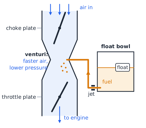
Before electronic injection became standard in the 1980s and 1990s, most gasoline engines used a carburetor. Air rushing through a narrowed section called a venturi speeds up and its pressure drops. That low pressure draws fuel from a float bowl through calibrated jets, and the fuel mixes with the air stream.
A throttle plate below the venturi controls airflow, and a choke enriches the mixture for cold starts. A carburetor meters fuel mechanically, with no oxygen sensor or computer in the basic design, so it cannot correct as precisely for temperature, altitude or wear. You may still see carburetors on small engines and older vehicles.
Follow the clean-air route through the intake
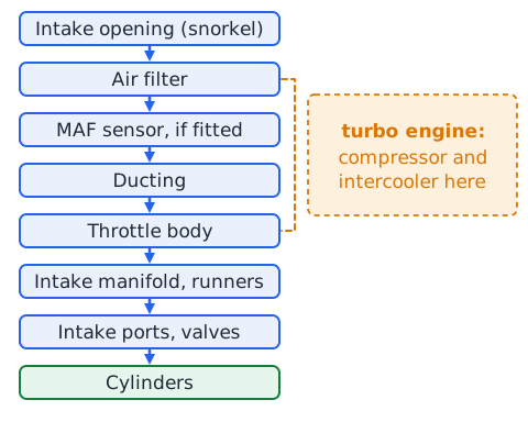
Air enters the engine through an intake opening, often a snorkel placed to draw cooler air. It passes through the air filter in its housing, then flows past a mass airflow sensor if one is fitted. Next it moves through ducting to the throttle body, where the throttle plate controls how much passes.
After the throttle, air enters the intake manifold, which divides it among the cylinder runners. It then flows through the intake ports and past the open intake valves into the cylinders. In a turbocharged engine, a compressor and often an intercooler sit between the filter and throttle.
Air filter versus fuel filter versus engine oil filter
Three common filters protect three different streams. The air filter, a pleated paper or fabric element in the intake housing, traps dust and debris in incoming air so they do not scratch cylinders and valves. The fuel filter traps rust and dirt in fuel before it reaches pump, regulator and injectors. The oil filter cleans circulating engine oil, catching wear particles and sludge so bearings stay protected.
They are not interchangeable and they sit in separate circuits. When a question asks which part removes particles from intake air, the answer is the air filter. A dirty air filter restricts airflow and can reduce power under load.
Throttle plate controls airflow in many gasoline engines
In most gasoline engines, the driver controls power by controlling air. The throttle plate is a round valve on a shaft inside the throttle body. At idle it is nearly closed; pressing the accelerator rotates it open so more air can flow. The control module then adds enough fuel to match the extra air.
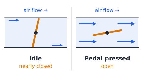
Older vehicles linked the pedal to the throttle with a cable. Many newer ones use electronic throttle control, in which a pedal position sensor reports to the computer and a motor positions the plate. Diesel engines traditionally have no throttle plate for power control; they vary output mainly by changing how much fuel is injected.
Intake manifold carries incoming air or charge
The intake manifold is a set of passages, called runners, that connects the throttle body to the intake ports of each cylinder. Its job is to carry incoming air, or an air-fuel charge in carbureted and throttle-body engines, and distribute it as evenly as possible among the cylinders.
Runner length and shape affect how well the engine breathes at different speeds. The manifold also provides mounting points for port injectors and connections for vacuum hoses and sensors. It should not be confused with the exhaust manifold, which collects burned gases leaving the cylinders.
Mass airflow sensor reports measured incoming air
A mass airflow (MAF) sensor sits in the intake duct between the air filter and the throttle body. A common design uses a heated wire or film. Air flowing past cools the element, and the electronics measure how much current is needed to hold its temperature. More air mass means more cooling and a larger signal.
The control module uses this measurement of air mass to calculate how much fuel to inject. Because it measures mass, not just volume, it automatically accounts for changes in air density with temperature and altitude. Dirt or oil on the element can make it under-report airflow, leading to a lean mixture.
Manifold absolute pressure gives another load clue
A manifold absolute pressure (MAP) sensor measures pressure inside the intake manifold relative to a perfect vacuum. At idle with the throttle nearly closed, the pistons pull the manifold well below atmospheric pressure, so the reading is low. When the throttle opens wide, manifold pressure rises close to atmospheric, or above it in a boosted engine.
Higher manifold pressure means more air is packed into each cylinder, so the reading is a good indicator of engine load. Some engines estimate airflow from MAP, engine speed and air temperature instead of using a MAF sensor; others use both. MAP measures pressure, not oxygen, fuel level or spark voltage.
Engine control module coordinates several independent tasks
The engine control module (ECM), also called the ECU or, when it also runs the transmission, the PCM, is the computer that manages the engine. It reads inputs such as airflow, manifold pressure, coolant and air temperature, throttle position, crankshaft and camshaft position, oxygen content and knock.
From these, it calculates and commands outputs: injector pulse width and timing, spark timing and coil firing, idle air or electronic throttle position, fuel pump operation and emission devices. It also stores diagnostic trouble codes. The ECM does not store fuel, filter air or open valves by itself; it coordinates the parts that do, based on sensor information.
Crankshaft position: timing reference for engine events
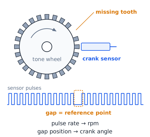
The crankshaft position sensor watches a toothed wheel, called a reluctor or tone wheel, on the crankshaft or flywheel. As teeth pass, the sensor produces pulses. A missing tooth or gap marks a known reference point.
From the pulses, the ECM calculates engine speed in rpm and the exact angle of the crankshaft. That angle tells it when each piston approaches top dead center, so it can schedule spark and injection events. If the crank signal is lost, many engines will crank but not start, because the controller cannot time ignition and fuel, even if the pump and fuel pressure are normal.
Camshaft position can reveal the four-stroke phase
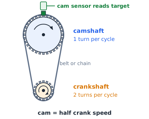
In a four-stroke engine, the crankshaft turns twice per complete cycle, so a piston reaches top dead center twice: once at the end of compression and once at the end of exhaust. The crank signal alone cannot tell which of these is happening.
The camshaft turns at half crankshaft speed, once per cycle. A camshaft position sensor reading a target on the cam therefore tells the ECM which stroke each cylinder is in. Combining cam and crank signals lets the controller fire each injector and coil in proper sequence. On engines with variable valve timing, the cam signal also confirms the actual cam angle.
Oxygen sensors support mixture feedback
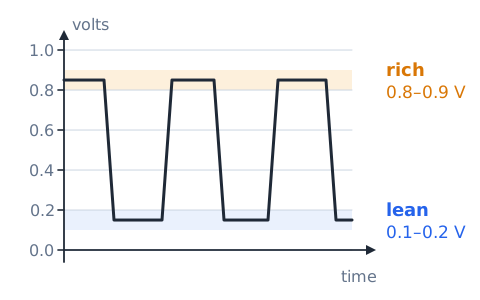
An oxygen sensor is threaded into the exhaust stream, usually before the catalytic converter, with a second sensor often placed after it. It compares oxygen in the exhaust with oxygen in outside air and produces a signal that reveals whether combustion was rich or lean.
A traditional zirconia sensor switches sharply: high voltage, near 0.8 to 0.9 V, when the exhaust shows a rich mixture, and low voltage, near 0.1 to 0.2 V, when lean. Wide-band air-fuel sensors give a more proportional reading. The ECM uses the upstream signal to trim fueling. The downstream sensor mainly checks how well the catalyst is working.
Open-loop and closed-loop control have different meanings
In open-loop control, the ECM sets fueling from stored tables and sensor inputs such as airflow and temperature but does not use exhaust oxygen feedback to correct the result. Engines run open loop during cold starts before the oxygen sensor is hot enough to work, and often at wide-open throttle, when a deliberately richer mixture protects the engine.
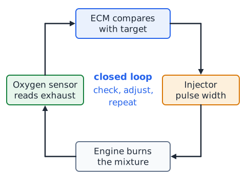
In closed-loop control, the ECM reads the oxygen sensor, compares the result with its target, and adjusts injector pulse width to correct the error, then checks again. This sensor to controller to injector cycle repeats continuously. Closed loop does not mean the engine is sealed; it refers to the feedback path.
Air–fuel ratio is a mass ratio
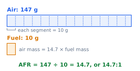
Air-fuel ratio (AFR) compares the mass of air with the mass of fuel in a mixture. It is a ratio of masses, not volumes, so both quantities must be in the same mass unit.
Here is the air mass and is the fuel mass, for example both in grams. The units cancel, so AFR is written as a number followed by :1. Example: 147 g of air mixed with 10 g of fuel gives
an AFR of 14.7:1. Do not add the masses.
Stoichiometric, rich and lean require a named reference
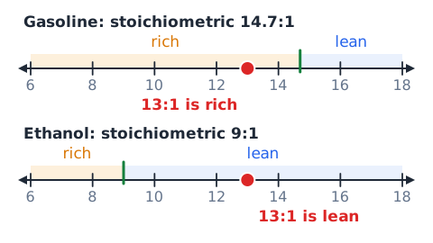
The stoichiometric ratio is the exact air-fuel ratio at which there is just enough oxygen to burn all the fuel completely, with neither leftover fuel nor leftover oxygen in theory. For typical pure gasoline it is about 14.7:1. Other fuels differ: diesel is near 14.5:1, and ethanol is about 9:1.
A rich mixture has more fuel than stoichiometric for that fuel, so its AFR number is lower. A lean mixture has less fuel and more excess air, so its AFR number is higher. Rich and lean only have meaning against a stated reference: 13:1 is rich for gasoline, but the same number would be lean for pure ethanol.
Lambda compares actual AFR with stoichiometric AFR
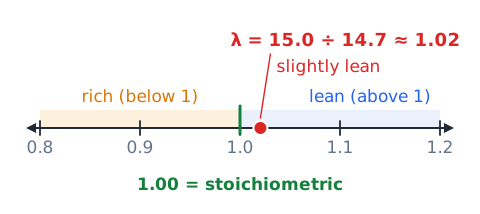
Lambda, written , expresses mixture strength relative to stoichiometric for whatever fuel is used.
Lambda has no units. A value of 1.00 means stoichiometric. Below 1 means rich, and above 1 means lean. Quick use: with a stoichiometric value of 14.7 and an actual AFR of 15.0,
slightly lean. Because lambda already divides by the reference, it works the same way for gasoline, ethanol blends or other fuels.
Ignition switch and battery are not the spark itself
The battery stores electrical energy at about 12 volts, and the ignition switch, or push-button start system, turns on power to the engine's control circuits, fuel pump relay and ignition system. Neither one produces the spark that ignites the mixture.
Twelve volts is far too low to jump a spark plug gap inside a compressed cylinder, which can require many thousands of volts. That step-up is done by the ignition coil, under command from the ECM. Turning the key to start also energizes the starter motor, which cranks the engine; the starter does not ignite fuel either. Keep power supply, switching and spark creation as separate ideas.
Ignition coil and spark plug have different roles
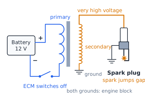
An ignition coil is a transformer. Current flows through its primary winding and builds a magnetic field. When the ECM or an ignition module abruptly switches off that current, the collapsing field induces a very high voltage, often tens of thousands of volts, in the secondary winding.
That voltage travels to the spark plug, directly in coil-on-plug designs or through a plug wire. The spark plug threads into the cylinder head; its center and ground electrodes are separated by a small gap. The high voltage jumps the gap as a spark inside the combustion chamber, igniting the mixture. In short, the coil creates the voltage and the plug delivers the spark.
Spark timing is not the same as valve timing
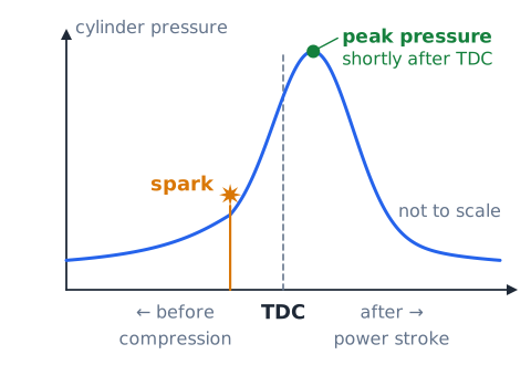
Spark timing, or ignition timing, describes when the spark plug fires, measured in crankshaft degrees relative to top dead center. A setting of 10 degrees BTDC means the spark occurs when the crank is 10 degrees before the piston reaches the top of its compression stroke.
Valve timing describes when the intake and exhaust valves open and close, set by the camshaft and its drive. It controls breathing, not ignition. Variable valve timing changes cam phasing, while the ECM changes spark timing electronically. A question about advancing spark is not a question about the timing belt or cam, though both are measured in crank degrees.
Why the ignition event may precede top dead center
The burn does not happen instantly. Once the spark lights the mixture, the flame takes a short time to spread across the chamber and build peak pressure. For the strongest push, peak pressure should arrive shortly after top dead center, as the piston starts down.
So the spark is fired before TDC, near the end of the compression stroke, giving the flame a head start. At higher rpm the piston moves faster, so the ECM generally advances the spark, firing earlier. Under heavy load or when knock is detected, it may retard the spark, firing later. Too much advance causes knock; too little wastes energy as heat.
Misfire is a symptom category, not one definite part failure
A misfire happens when a cylinder fails to burn its charge properly on a given cycle. The driver may feel shaking, rough idle or hesitation, and the ECM may detect it as a brief slowdown in crankshaft speed.
Many problems can cause it. Ignition causes include a worn plug, failed coil or damaged wire. Fuel causes include a clogged or stuck injector or low fuel pressure. Air and compression causes include a vacuum leak, a burned valve or worn rings. Since a misfire describes what happened, not why, a good technician checks spark, fuel and compression in turn rather than assuming one part is bad.
Knock sensing protects operation under adverse conditions
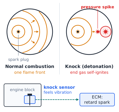
Engine knock, also called detonation or pinging, occurs when part of the mixture ignites on its own after the spark, ahead of the normal flame front. The two pressure waves collide, causing a sharp metallic sound and pressure spikes that can damage pistons, rings and head gaskets.
A knock sensor, usually a piezoelectric device bolted to the block, detects the vibration frequencies typical of knock. When the ECM sees knock, it retards spark timing for the affected cylinder or cylinders until knock stops, then gradually restores advance. Knock is more likely with low-octane fuel, high intake temperatures, heavy load, carbon buildup or excessive advance.
Octane rating and the correct fuel misconception
A gasoline's octane rating measures its resistance to knock, not the amount of energy it contains. Higher-octane fuel can withstand more compression and more spark advance before self-igniting. The number at the pump in the US is the average of two lab test methods.
Engines with high compression or turbocharging may require premium fuel to avoid knock. An engine designed for regular will usually see little or no benefit from premium, because its timing and compression do not take advantage of the extra knock resistance. Use the grade the manufacturer specifies. Using a lower grade than required can trigger knock and timing retard.
Catalytic converter versus combustion chamber
Combustion takes place in the combustion chamber, the space above the piston bounded by the cylinder head and valves. That is where fuel burns and pushes the piston.
The catalytic converter is a separate device in the exhaust system, after the engine. Inside, a ceramic honeycomb is coated with metals such as platinum, palladium and rhodium. As hot exhaust passes over them, chemical reactions convert harmful gases into less harmful ones. It treats exhaust that has already left the engine; it does not ignite fuel to make power. A catalyst that overheats, often because unburned fuel from a misfire is reaching it, can be damaged.
Recognize onboard diagnostics without overinterpreting them
Since the 1996 model year, light vehicles sold in the US use OBD-II, a standardized onboard diagnostic system. The ECM monitors sensors and emission-related systems; when it finds a fault, it stores a diagnostic trouble code and may light the check-engine lamp. A scan tool plugged into the standard connector under the dashboard reads the codes and live data.
A code points to a circuit or condition, such as a system running lean or a misfire in cylinder 3. It rarely names the exact failed part. A lean code could come from a vacuum leak, weak pump or dirty MAF sensor. Treat a code as a starting clue, then test.
When engine load increases, coordination matters
Consider a car merging onto a highway. The driver presses the pedal, the throttle opens and airflow rises. The MAF or MAP sensor reports the increase, and the ECM lengthens injector pulse width to keep the mixture correct. It may enrich slightly at full load to protect the engine and catalyst.
At the same time, the ECM adjusts spark timing for the new speed and load, listening to the knock sensor and retarding if needed. The fuel pump must keep pressure steady despite higher flow, and in a turbocharged engine boost rises. Each subsystem does its own job, but power arrives smoothly only when the controller coordinates them.
Boost devices compress intake air, not fuel alone
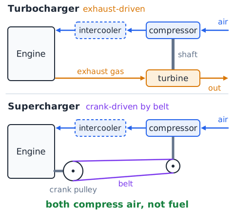
A turbocharger and a supercharger are both forced-induction devices. Each one is a compressor that pushes air into the intake at higher than atmospheric pressure, packing more air mass into each cylinder. More air allows more fuel to be burned, so the engine makes more power for its size.
A turbocharger is spun by a turbine driven by exhaust gas flow. A supercharger is driven mechanically by the crankshaft, usually with a belt. Compressing air heats it, so many systems use an intercooler to cool the charge and make it denser. These devices compress air, not fuel; the fuel system must still add matching fuel. Higher cylinder pressure also raises knock risk, so boosted engines often need premium fuel and careful spark control.
Avoid universal fuel pressure and spark-gap figures
Specifications vary widely between engines, so be cautious with any single number presented as universal. Port injection systems typically run at moderate pressure, while gasoline direct injection and diesel common-rail systems operate at pressures many times higher. Carbureted systems use only a few psi.
Spark plug gaps also differ by engine and plug type, and some plugs come pre-gapped for a specific application. Ignition timing values, idle speeds and sensor voltages are likewise model specific. On a test, if a question supplies a figure, use it. In real service work, look up the manufacturer's specification instead of relying on a remembered general value.
Recognize lean operation without inferring an exact cause
A lean mixture has more air relative to fuel than the target. Signs can include hesitation on acceleration, surging, rough idle, a lean diagnostic code, upstream oxygen sensor readings that stay low, and fuel trims that the ECM has pushed strongly positive to add fuel.
Several conditions can produce it: unmetered air entering through a vacuum leak, a dirty MAF sensor under-reporting airflow, a weak fuel pump, a clogged filter or restricted injectors. Knowing the mixture is lean narrows the search to air and fuel metering, but it does not prove which part is responsible. Further tests are needed.
Engine oxygen comes from air, not gasoline alone
Gasoline is mainly hydrocarbons, molecules of hydrogen and carbon. To burn, those atoms must combine with oxygen, forming mostly carbon dioxide and water vapor. Gasoline does not carry the oxygen it needs; it comes from the air drawn into the engine. Air is roughly 21 percent oxygen and 78 percent nitrogen by volume.
That is why an engine needs so much more air than fuel, about 14.7 times the fuel's mass at stoichiometric. Restricting air, as with a clogged air filter, limits how much fuel can be burned. Oxygenated fuels such as ethanol blends contain a little oxygen, but the engine still depends on air.
Four-stroke timing connects fuel and spark events
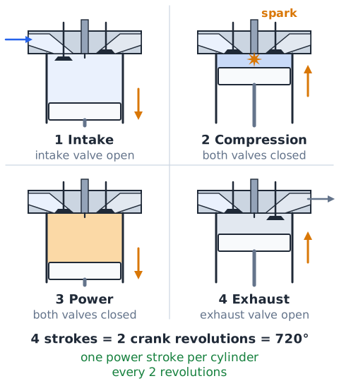
A four-stroke engine completes one cycle in four piston strokes over two crankshaft revolutions, or 720 degrees. On intake, the intake valve opens and the descending piston draws in air or air-fuel mixture. On compression, both valves close and the rising piston squeezes the charge. Near the end of compression, the spark fires in a gasoline engine, or fuel is injected into hot air in a diesel.
On the power stroke, expanding gases push the piston down. On exhaust, the exhaust valve opens and the rising piston pushes burned gases out. Each cylinder makes one power stroke every two revolutions, so injection and spark must be scheduled to match.
What the intake air temperature sensor contributes
The intake air temperature (IAT) sensor is usually a thermistor, a resistor whose resistance changes with temperature. In common designs, resistance drops as air gets warmer. It may be built into the MAF sensor housing or mounted separately in the intake duct or manifold.
Air temperature affects air density: cold air is denser and holds more oxygen per unit volume than hot air. In speed-density systems that calculate airflow from MAP and rpm, the ECM needs IAT to estimate air mass accurately. The ECM also uses this reading to adjust spark timing, since hot intake air raises knock risk. A failed IAT sensor can make fueling or timing slightly wrong.
Troubleshooting starts by isolating a function
When an engine will not start or runs poorly, start by asking which basic requirement is missing: fuel, air, spark or compression, plus correct timing. Narrow the problem to one function before suspecting any single part.
For example, if an engine cranks normally but will not start, a technician might check for spark at a plug, check fuel pressure at the rail, and confirm the ECM sees a crank signal. If spark and timing signals are present but fuel pressure is zero, attention shifts to the pump, its relay and fuse. Testing functions in a logical order saves time and avoids replacing good parts.
Read simplified system diagrams accurately
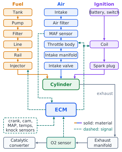
Test diagrams often show boxes connected by arrows. Read the arrows: they show the direction in which fuel, air, exhaust or a signal moves. A solid path might carry fuel from tank to pump to filter to rail to injector; another might carry air from filter to MAF sensor to throttle to manifold.
Signal lines usually run from sensors into the ECM and from the ECM out to actuators such as injectors and coils. Before answering, identify what each line carries and which way it points. A part placed before the throttle in an airflow path cannot be measuring exhaust gas.
Differentiate sensor, controller and actuator
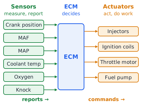
Engine electronics follow a simple pattern. A sensor measures a condition and sends a signal: crankshaft position, MAF, MAP, coolant temperature, oxygen and knock sensors are examples. The controller, the ECM, receives those signals, compares them with its programming and decides what to do.
An actuator receives a command and performs a physical action: fuel injectors open, ignition coils fire, the electronic throttle motor moves, the fuel pump runs. A useful test is to ask whether the part reports information or does work. An oxygen sensor reports; an injector acts. Swapping these roles is a common source of wrong answers.
Recognize gasoline three-way catalyst dependence
Most gasoline vehicles use a three-way catalytic converter, so named because it treats three pollutants at once. It converts carbon monoxide to carbon dioxide, unburned hydrocarbons to carbon dioxide and water, and nitrogen oxides back to nitrogen and oxygen.
The first two reactions need some oxygen, while the third works best when little oxygen is present. All three work efficiently only in a narrow window very close to stoichiometric, lambda near 1.00. That is why closed-loop fueling with oxygen sensors matters so much for emissions. Diesels run lean and need different aftertreatment, such as particulate filters and NOx reduction systems.
Make safe numerical assumptions explicit
Many calculation questions rely on a reference value, and you should state which one you are using. If a problem gives a stoichiometric ratio, use that number even if it differs from the familiar 14.7. If it gives none and clearly involves gasoline, 14.7:1 is the usual textbook assumption, but write it down so the reasoning is clear.
Do the same for timing, rpm or time intervals. Keep units consistent: grams with grams, milliseconds with milliseconds. Round only at the end. If an answer depends on information that is not given, such as an exact power increase from a timing change, avoid choices that claim more precision than the data supports.
Integrated map of fuel, air and ignition subsystems
Picture the whole system as three supply lines meeting in the cylinder under one manager. The fuel line runs tank, pump, filter, line, rail and injector. The air line runs intake, air filter, MAF sensor, throttle body, intake manifold and intake valve. The ignition line runs battery and switch, ECM command, coil and spark plug, or simply hot compressed air in a diesel.
The ECM sits at the center, reading crank and cam position, airflow or MAP, temperatures, oxygen and knock, then commanding injectors, coils and throttle. After combustion, exhaust leaves through the exhaust manifold, past oxygen sensors and through the catalytic converter.
Worked 1 — map the gasoline fuel path
Problem: A diagram lists rail, tank, injector, filter and pump in scrambled order. Put them in the order fuel travels in a typical electronic gasoline system.
Step one: fuel starts where it is stored, the tank. Step two: the pump draws it out and pressurizes it. Step three: the filter removes particles. Step four: the rail holds pressurized fuel at the engine. Step five: the injector meters it into the port or cylinder.
Answer: tank, pump, filter, rail, injector.
Worked 2 — recognize where port fuel enters
Problem: An engine has one injector per cylinder, each aimed at the back of an intake valve. Where does fuel first meet air, and is this port or direct injection?
Step one: the injector tip points into the intake port, outside the combustion chamber. Step two: fuel sprays into air flowing toward the intake valve and mixes there. Step three: the mixture enters the cylinder when the valve opens.
Answer: fuel meets air in the intake port, so this is port fuel injection.
Worked 3 — calculate a textbook air–fuel ratio
Problem: A test mixture contains 375 g of air and 25 g of fuel. Find the AFR.
Divide air mass by fuel mass; do not add them.
The grams cancel. Answer: 15:1. Compared with 14.7:1 gasoline stoichiometric, this mixture is slightly lean.
Worked 4 — diagnose rich versus lean from masses
Problem: Using 14.7:1 as the reference, compare two samples that each contain 300 g of air. Sample A has 25 g of fuel; sample B has 20 g.
Sample A at 12:1 is below 14.7, so it is rich. Sample B at 15:1 is above 14.7, so it is lean. Less fuel with the same air raises the ratio.
Worked 5 — calculate lambda from an explicit target
Problem: A gasoline engine has a stated stoichiometric AFR of 14.7. A wide-band sensor reports an actual AFR of 13.23. Find lambda and the mixture direction.
Lambda is below 1.00, so the mixture is rich. In plain terms, there is only 90 percent of the air needed for complete combustion of the fuel present.
Worked 6 — calculate required air mass
Problem: A lab test uses an illustrative target AFR of 14.5:1. If 18 g of fuel will be burned, how much air is needed?
Rearrange the ratio to solve for air mass.
Answer: 261 g of air.
Worked 7 — convert an ignition timing statement
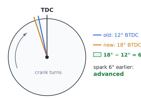
Problem: Spark timing changes from 12 degrees BTDC to 18 degrees BTDC. Describe the change.
Step one: a larger BTDC number means the spark happens earlier, before the piston reaches the top.
Answer: timing was advanced by 6 crankshaft degrees. If it had moved from 18 to 12 degrees BTDC instead, it would be retarded by 6 degrees.
Worked 8 — classify feedback correctly
Problem: A warm engine at steady cruise shows the upstream oxygen sensor reading lean. The ECM lengthens injector pulse width slightly, and the next readings move toward stoichiometric. Is this open-loop or closed-loop control?
Step one: the controller reads a measured result, exhaust oxygen. Step two: it changes its output, fuel, based on that result. Step three: it checks again.
Answer: closed-loop fueling correction, because the output is adjusted from feedback.
Worked 9 — distinguish sensor from actuator
Problem: Classify these four parts: knock sensor, ignition coil, MAP sensor, electronic throttle motor.
Step one: ask whether each part reports a condition or performs an action. Step two: the knock sensor reports vibration and the MAP sensor reports manifold pressure, so both are sensors. Step three: the coil produces high voltage on command and the throttle motor moves the plate, so both are actuators.
Answer: two sensors and two actuators, with the ECM deciding between them.
Worked 10 — compare gasoline and diesel cycles
Problem: State how a gasoline engine and a conventional diesel differ during the compression stroke and the start of power.
Gasoline: a fuel-air mixture, or air with fuel added by direct injection, is compressed at a moderate ratio, and a timed spark from the plug starts the burn near the end of compression.
Diesel: only air is compressed, at a much higher ratio, making it very hot. Fuel is injected near the end of compression and self-ignites. Answer: the ignition method is the key difference.
Worked 11 — crank revolutions and normal firing events
Problem: A four-stroke, six-cylinder engine runs steadily at 3000 rpm. How many power events occur per minute in an ideal model?
Each cylinder fires once every two crank revolutions.
Answer: 9000 power events per minute, which is 150 per second.
Worked 12 — locate an air restriction
Problem: An engine idles normally but feels weak at full throttle. The air filter is dark and packed with dust, and the fuel pressure test is within specification. Where is the likely restriction?
Step one: fuel delivery checks out, so look at the air side. Step two: at idle the engine needs little air, so a partial restriction may not show. Step three: at full throttle, demand is high and a clogged filter limits airflow and power.
Answer: the intake air filter; replace it and retest.
Worked 13 — identify ignition energy steps
Problem: Put these ignition steps in order for a coil-on-plug gasoline engine: spark jumps the plug gap; ECM receives the crank position signal; coil primary current is switched off; battery supplies 12 V to the coil primary.
Step one: the battery supplies power. Step two: the ECM uses crank position to decide when to fire. Step three: it switches off primary current, inducing high secondary voltage. Step four: the spark jumps the gap.
Answer: battery, crank signal, primary off, spark.
Worked 14 — calculate injector duty in a stated interval
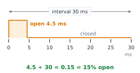
Problem: An injector is commanded open for 4.5 ms during a specified 30 ms interval. What fraction of the interval is it open?
Divide open time by the interval, keeping both in milliseconds.
Answer: 0.15, or 15 percent of the interval. A longer pulse in the same interval delivers more fuel.
Drill 1 — follow two material streams
Prompt: Name the part between the air filter and throttle body in many intakes. Answer: the mass airflow sensor.
Prompt: What part sits between the fuel pump and the fuel rail to catch debris? Answer: the fuel filter.
Prompt: After the throttle body, where does air go next? Answer: the intake manifold, then the intake ports.
Prompt: Where do the fuel and air streams finally meet in direct injection? Answer: inside the cylinder.
Drill 2 — classify the six labels
Prompt: Classify each as sensor, controller or actuator: injector, oxygen sensor, ECM, ignition coil, crankshaft position sensor, throttle motor.
Answer: injector, actuator. Oxygen sensor, sensor. ECM, controller. Ignition coil, actuator. Crankshaft position sensor, sensor. Throttle motor, actuator.
Prompt: How many of the six are sensors? Answer: two.
Drill 3 — work an AFR comparison
Prompt: Find the AFR for 360 g of air with 24 g of fuel. Answer:
so 15:1.
Prompt: Find the AFR for the same 360 g of air with 30 g of fuel. Answer:
so 12:1.
Prompt: Against 14.7:1, which mixture is richer? Answer: the 12:1 mixture, because it has more fuel for the same air.
Drill 4 — identify two ignition mechanisms
Prompt: What starts combustion in a conventional gasoline engine? Answer: a timed spark across the spark plug gap.
Prompt: What starts combustion in a conventional diesel engine? Answer: fuel injected into air that compression has made hot enough to ignite it.
Prompt: Does a diesel need a spark plug for each power stroke? Answer: no; glow plugs only assist cold starts.
Prompt: Two engines both use direct injection. What could still differ? Answer: the ignition mechanism.
Drill 5 — feedback and knock control
Prompt: The ECM adds fuel after the oxygen sensor reads lean. What control mode is this? Answer: closed loop.
Prompt: A cold engine ignores the oxygen sensor right after startup. Which mode? Answer: open loop.
Prompt: The knock sensor detects pinging. What does the ECM usually do? Answer: retard spark timing until knock stops.
Prompt: Does premium fuel add power to an engine designed for regular? Answer: usually little or none.
Drill 6 — interpret a cautious diagnostic scenario
Prompt: A car shows a lean code and rough idle. Should the oxygen sensor be replaced right away? Answer: no; the sensor may simply be reporting a real lean condition.
Prompt: What should be checked? Answer: approved tests for vacuum leaks, MAF readings, fuel pressure and injector function.
Prompt: Is it acceptable to open a high-pressure fuel line while the engine runs as a quick check? Answer: no; that creates a fire and injection-injury hazard. Follow the service procedure.
Exam strategy — map flows before selecting parts
When a question names a symptom or part, first decide which stream is involved: fuel, air, ignition, exhaust or signal. Then decide the part's role in that stream: store, move, clean, measure, decide, meter or ignite. Many wrong choices name a real part from the wrong stream, such as a catalytic converter offered as an intake filter.
For sensor questions, ask what physical quantity is measured. For calculations, write the formula first, state the reference value, check units and see whether the answer is sensible: an AFR near 10 to 20 is plausible, while 300:1 signals that masses were added. For diagnostic questions, prefer answers that test before replacing and that follow safe procedures.
Common traps — pressure, sensors and mixture claims
Trap one: thinking a higher AFR means more fuel. It is wrong because the fuel mass is in the denominator. Fix: higher AFR or lambda above 1 means lean.
Trap two: treating a sensor as the cause of every code. A sensor often reports a real problem elsewhere. Fix: verify the condition before replacing the sensor.
Trap three: quoting one fuel pressure or plug gap for all engines. Values differ by design. Fix: use the figure the question or service data gives.
Trap four: confusing spark timing with valve timing, or advance with retard. Fix: a larger BTDC number is more advanced, earlier spark.
Trap five: saying diesels use spark plugs. Fix: diesels rely on compression heat.
Quick review — fuel, air and ignition
Combustion needs fuel, air for oxygen, and ignition. Fuel flows tank, pump, filter, rail, injector; the injector meters fuel by pulse width into the port or the cylinder. Air flows filter, MAF sensor, throttle, intake manifold, valve. Gasoline engines ignite with a timed spark from coil and plug; diesels ignite fuel in hot compressed air.
The ECM reads sensors such as crank, cam, MAF, MAP, IAT, oxygen and knock, and commands actuators such as injectors, coils and throttle. Closed loop uses oxygen feedback; open loop does not.
Lambda below 1 is rich, above 1 is lean. A larger BTDC number means more advanced spark. The catalytic converter cleans exhaust after combustion.
 English ▾